Page is loading ...

User’s Guide Model CA250
400A AC/DC Current Clamp-on MultiMeter Adaptor
CA250-en-EU_V1.5 8/14
Introduction
Congratulations on your purchase of
the Extech CA250 400 Amp AC/DC
Clamp-On MultiMeter Adaptor. With
this clamp adaptor, a current can be
measured by simply clamping around
a single conductor. The adaptor
outputs an mV signal that is
proportional to the measured current
and displayed on a DMM. Careful use of this device will provide years of
reliable service.
Specifications
Measurement Ranges 0 to 40 Amps AC/DC
0 to 400 Amps AC/DC
Adaptor Output 10mV/Amp on the 0 to 40A range
1mV/Amp on the 0 to 400A range
Frequency range 50/60Hz
Safety
EN61010-1 and IEC61010-1 2nd Edition (2001)
to Category III 600V and Category IV 300V;
Pollution Degree 2 in accordance with IEC 664
indoor use.
Standards
C
C
Accuracy 0 to 40A ± (2.5% + 0.1A)
0 to 400A ± (2.8% + 0.5A)
Jaw size 30mm (1.2")
Operating Conditions 0 to 50
o
C (32 to 122
o
F) < 70% RH
Storage Conditions -20 to 70
o
C (-4 to 158
o
F) < 80% RH
Battery 2 – 1.5V “AAA”
Dimensions/Weight 146 x 60 x 32mm (5.8 x 2.3 x 1.3");
226g (8oz)
Safety
Safety Symbols
This symbol, adjacent to another symbol or terminal,
indicates the user must refer to the manual for further
information.
This symbol indicates that double insulation is used.
WARNING: This indicates that a potentially hazardous condition which,
if not avoided, could result in death or serious injury.
Safety Precautions
1. WARNING: Improper use of this meter can cause damage, shock,
injury or death. Read and understand this manual before operating
the meter.
2. Inspect the condition of the test leads and the meter itself for any
damage before operating the meter. Repair or replace any damage
before use.
3. Do not use on non-insulated conductors at voltages greater than
600VAC rms or DC.
You, as the end user, are legally bound (EU Battery
ordinance) to return all used batteries, disposal in the
household garbage is prohibited! You can hand over your
used batteries / accumulators at collection points in your
community or wherever batteries / accumulators are sold!
Disposal: Follow the valid legal stipulations in respect of the
disposal of the device at the end of its lifecycle
Current Measurements
NOTE: This device has a 30-minute automatic shut-off feature
1. Set the DMM range to AC mV when measuring AC amps and DC
mV when measuring DC amps or to the lowest voltage range.
2. Connect the RED test lead to the DMM '+' Voltage terminal and
the BLACK lead to the '-' COM terminal.
3. Set the adaptor to the 40A (AC or DC) or the 400A (AC or DC)
range.
4. Press the Jaw Trigger to open the jaw and clamp around a single
conductor.
5. The unit will output an AC or DC voltage proportional to the
measured current. (40A range:10mV/A, 400A range:1mV/A)
6. Read the voltage on the DMM display and interpret as
current.(direct mV to A on the 400A range, divide by 10 on the
40A range)
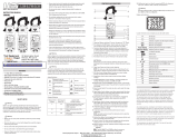
1. Read mV
2. Set to AC or DC mV
3. Voltage Input
4. NCV detector
5. NCV indicator
6. DC Zero adjust
DC Zero
A hysteresis voltage may appear when the clamp is set to the DC
position. With no conductor in the jaw, adjust the DC Zero adjust until
the DMM display indicates zero. If the voltage is beyond the range of
the zero adjust, snap the jaw open and shut several times to clear the
hysteresis. Set DMM to DC mV range.
Note: Verify the zero or re-zero the unit prior to all DC current
measurements and range changes.
Note: DC current measurements are polarity sensitive. Reverse the
conductor direction in the jaw to change the polarity.
Note: Do not apply voltage to the clamp adaptor’s test leads
Note: Clamp a single conductor only, do not clamp the hot and neutral
simultaneously.
Note: The clamp jaws must be fully closed for proper measurements.
On large conductors or line splitters, make sure there is no gap
between the upper and lower jaw.
Non-Contact AC Voltage Measurements
1. Touch the probe tip to the hot conductor or hold next to the hot
side of the electrical outlet.
2. If AC voltage is present, the detector LED will illuminate.
Copyright©2014FLIRSystems,Inc.
Allrightsreservedincludingtherightofreproductioninwholeorinpartinanyform
ISO‐9001Certified
www.extech.com
X
WARNING: Risk of Electrocution. Before use, always test the
Voltage Detector on a known live circuit to verify proper operation
1
2
3
4
5
6
/


