Page is loading ...

CATIII 600V
CATIV
300V
DISCONNECT TEST LEADS
30V
TEMP
DL379B
Hi-NCV-Lo
MFD
µA
600V
CAT III
400A
INSTRUCTION MANUAL
ENGLISH
DL369/DL379B/DL389
FEATURES
• 3 ¾ digit, 4000 count LCD display
• Auto-ranging with manual ranging capability
• MIN/MAX (Peak Hold). All ranges except capacitance & frequency.
• Frequency, duty cycle, data hold
• Auto power off
• Dual display
• Built-in test lead storage
• Backlit display + Worklight (DL379B & DL389)
• Detachable current clamp head (DL379B & DL389)
• Temperature (DL379B & DL389)
• Magnetic mount (DL379B & DL389)
• True RMS measurement (DL389 only)
SAFETY NOTES
Warning
Refer to user guide regarding potential hazard and proper instructions.
Before using this meter, read all safety information carefully. In this manual
the word “WARNING” is used to indicate conditions or actions that may
pose physical hazards to the user. The word “CAUTION” is used to indicate
conditions or actions that may damage this instrument.
Warning
• Before each use, verify meter operation by measuring a known voltage
or current.
• Never use the meter on a circuit with voltages that exceed the category
based rating of this meter.
• Do not use this meter during electrical storms or in wet weather.
• Do not use the meter or test leads if they appear damaged.
• Keep your fingers away from the test lead’s metal probe contacts when
making measurements.
• Ensure meter leads are fully seated and keep fingers away from metal
probe contact when making measurements. Always grip the leads
behind the finger guards molded into the probe.
• Do not open the meter to replace batteries white the probes are
connected.
• Use caution when working with voltages above 60V DC or 25V AC RMS.
Such voltages pose shock hazards.
• To avoid false readings that can lead to electrical shock, replace
batteries if a low battery indicator appears.
• Unless measuring voltage or current, shut off and lock out power before
measuring resistance or capacitance.
• Always adhere to national and local safety codes. Use proper personal
safety equipment (PPE) to prevent shock and arc blast injury where
hazardous live conductors are exposed.
• Always turn off power to a circuit or assembly under test before cutting,
unsoldering or breaking the current path. Even small amounts or current
can be dangerous.
• Always disconnect the live test leads before disconnecting the common
test lead from the circuit.
• In the event of electrical shock, ALWAYS bring the victim to the
emergency room for evaluation, regardless of victim’s apparent
recovery. Electrical shock can cause unstable heart rhythms that
may need medical attention.
• If any of the following occur during testing, turn off the power source
to the circuit being tested: arching, flame, smoke, extreme heat, smell of
burning materials or discoloration or melting of components.
Warning
Higher voltages and currents require greater awareness of physical safety
hazards. Before connecting the test leads; turn off power to the circuit
under test; set meter to the desired function and range; connect the test
leads to the meter first, then connect to the circuit under test. Reapply
power. If an erroneous reading is observed, disconnect power immediately
and recheck all settings and connections.
Warning
This meter is designed for trade professionals who are familiar with the
hazards of their trade. Observe all recommended safety procedures that
include proper lock-out utilization and the user of personal protective
equipment that includes safety glasses, gloves and flame resistant clothing.
Symbol Definitions
Equipment is safe for
connection and disconnection
to Live conductors
Ground
~
AC
Alternating Current
Warning or Caution
DC
Direct Current
Double Insulation
(Protection Class II)
Not Applicable to
Identified Model
Battery
Category Definitions
Measurement
Category
Short-Curcuit
(typical) kA
a
Location in the
building installation
II < 10 Circuits connected to mains socket
outlets and similar points in the
MAINS installation
III < 50 Mains distributions parts of the
building
IV > 50 Source of the mains installation in
the building
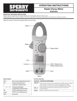
CONTROLS AND INDICATORS
CATIII 600V
CATIV
300V
DISCONNECT TEST LEADS
30V
TEMP
DL379B
Hi-NCV-Lo
MFD
µA
600V
CAT III
400A
1. Clamp jaw: Measure inductive AC current. Jaw opens to 1.25” (32mm).
2. Wire Separation Tab/NCV Sensor: Used to isolate an individual wire
from a bundle for testing. NCV sensor helps detect live voltage.
3. Conductor Alignment Marks: Used to aid in the visual alignment of
a conductor when measuring inductive amperage. Greatest accuracy
is achieved when the conductor, inside the clamp, is centered at the
intersection of these marks.
4. Test Lead Holder: Used for hands-free use of one of the test probes.
5. Hand Guard: Used as a point of reference for the operator’s safety.
Warning
Always keep your hands and fingers behind the hand guards when
measuring current on exposed conductors. Contact may result in serious
injury.
6. Clamp Lever: Opens and closes current clamp jaw.
NOTE: The clamp uses a high-tension spring to close the jaw. Do not
allow fingers or objects to become pinched in the hinge as jaws close.
7. NCV (Non-Contact Voltage) Button: Activates non-contact voltage
function. Dual level indication on DL379B only.
8. Range Button: Used to select range for upper and lower display
readings.
9. Hold/Backlight Button: Freezes readings or activates backlight and
worklight. (Worklight available on DL379B and DL389)
10. Min/Max Button: Activates MIN/MAX capture function, cycles through
minimum and maximum values. Press and hold for 2 seconds to return to
live readings.
11. Rotary Function Switch: Turns meter on and is used to select the range
or function.
12. Upper Display: Used to display current when measuring with the clamp
head, or UEi’s optional current hook adapter. Displays output from other
accessories when connected to UEi’s meter base.
13. Lower Display: Used to display input to test lead jacks. Includes AC/
DC volts, frequency, resistance, diode, capacitance and AC/DC
microamps (µA).
14. Select Button: Used to choose a measurement mode from selections
with multiple options such as AC or DC volts; AC or DC microamps;
resistance, diode, capacitance or continuity; Fahrenheit or Celsius.
15. Temperature Input Jack: Input jack for K-type thermocouple probe
(available on DL379B and DL389).
16. Temperature Input Jack Lock: Move switch down to measure
temperature.
NOTE: Test leads must be removed from input jacks prior to operating
the temperature function.
17. Hz/Duty Cycle Button: Used to toggle between frequency and duty cycle
when in AC voltage measurement mode.
18. Common Terminal: The black test lead is plugged into this input jack to
supply ground or “low” reference for all measurements.
19. Maximum Category Indicator: Indicates maximum voltage for the rated
working category.
Warning
DO NOT exceed 1000V DC or AC RMS at either the common or
multifunction input jacks as measured from earth ground.
20. Multifunction Input Jack: Used for measuring AC/DC volts, frequency,
duty cycle, resistance, diode, continuity, and capacitance.
Warning
Use CAT III listed test leads or higher. DO NOT attempt to measure more
than 1000V DC, 750V AC or 2000µA DC.
Displays and Indicators
Location of function icons on display may vary be model number.
~
AC indicator
DC indicator
-
Indicates a negative value (DC negative voltage)
M
AX
Maximum value displayed
MIN
Minimum value displayed
A (top display)
Displaying Amps from clamp jaw or adapter
ADP (top display)
Displaying value from adapter
Low battery indication
HOLD
Hold function
Diode function
Continuity function
nF / µF
Capacitance function (nanofarads or microfarads)
nA
Microamps function (1µA is 0.000001 Amp)
Hz
Frequency function
%
Duty cycle function
mV
Millivolts function (1 mV is 0.001 Volt)
APO
Auto power off is active
AT
Auto Range mode is active
O.L.
Displayed if input value exceeds selected range
Ω
Resistance function
°F
Degrees Fahrenheit
°C
Degrees Celsius
WARRANTY
The DL369/DL379B/DL389 is warranted to be free from defects in materials
and workmanship for a period of three years from the date of purchase.
If within the warranty period your instrument should become inoperative
from such defects, the unit will be repaired or replaced at UEi’s option.
This warranty covers normal use and does not cover damage which
occurs in shipment or failure which results from alteration, tampering,
accident, misuse, abuse, neglect or improper maintenance. Batteries and
consequential damage resulting from failed batteries are not covered by
warranty.
Any implied warranties, including but not limited to implied warranties
of merchantability and fitness for a particular purpose, are limited to the
express warranty. UEi shall not be liable for loss of use of the instrument or
other incidental or consequential damages, expenses, or economic loss, or
for any claim or claims for such damage, expenses or economic loss.
A purchase receipt or other proof of original purchase date will be required
before warranty repairs will be rendered. Instruments out of warranty will
be repaired (when repairable) for a service charge.
This warranty gives you specific legal rights. You may also have other
rights which vary from state to state.
2
1
3
6
7
8
9
10
14
18
19
4
5
11
12
13
15
16
17
20
99 Washington Street
Melrose, MA 02176
Phone 781-665-1400
Toll Free 1-800-517-8431
Visit us at www.TestEquipmentDepot.com
Test Equipment Depot - 800.517.8431 - 99 Washington Street Melrose, MA 02176
TestEquipmentDepot.com

OPERATING INSTRUCTIONS
Auto Power Off
After powering off, the meter will turn on again when you change ranges,
rotate the selector dial or press a button.
NOTE: The APO is disabled during MIN/MAX mode.
Backlight/Worklight (DL379B and DL389 only)
Press and hold the HOLD button for 2 seconds to activate. Lights
automatically turn off in 2 minutes to save battery life.
NOTE: After activating the lights, quick press to activate the hold mode.
Automatic / Manual Range
The meter defaults to auto range mode and AT is indicated on the display
while active. Press the RANGE button to cycle through available ranges.
Selecting a specific range will put the meter in manual range mode and AT
will no longer be displayed on screen. Press and hold the RANGE button to
return to auto ranging mode.
NOTE: Manual ranging will provide a faster input response over auto
range.
MIN/MAX
When using the MIN/MAX capture mode for amps, it is recommended that
you first select the range of the expected maximum value. If this is not done
it will lock in the lowest range for the initial measurement. If the maximum
value exceeds this range the meter will capture O.L. as the maximum value.
Data Hold
Press the HOLD button to activate. This will freeze the reading and range in
the display for review.
Measuring AC Amps
• Press SELECT to change
between AC/DC
• Press RANGE to select range
prior to using MAX/MIN.
NOTE: Max capture is useful for
motor inrush current.
Measuring AC/DC Volts
• Press SELECT to change
between AC/DC
Measuring Frequency or Duty Cycle
• Must be AC Volt or AC µA
mode
• Press HZ/DUTY to select and
change between frequency or
duty cycle
NOTE: Frequency greater than
1MHz will display 0.000
Measuring Resistance and Capacitance
Warning
DO NOT measure resistance on a live circuit.
Warning
Safely discharge capacitor before measurement.
NOTE: Leave meter connected to the capacitor for 10 seconds allowing the
reading to settle. Larger capacitors could take up to 60 seconds.
Measuring Continuity and Diode
Press SELECT to change between continuity and diode
NOTE: Continuity tone sounds at approximately <50Ω.
NOTE: Shows voltage drop if forward biased and O.L. if reversed biased.
Measuring Temperature (DL379B and DL389 only)
Warning
Disconnect test lead probes from
voltage source and meter.
• Slide temperature input
jack lock switch down prior to
connecting temperature probe.
• Press SELECT to change
between Fahrenheit or Celsius.
Temperature Calibration
• Connect temperature probe as directed above.
• Remove battery cover. Place temperature probe in a known standard
temperature. Stirred crush ice in distilled water can be used for 32°F.
• Adjustments are made by accessing the potentiometer through the lower
right access port in the battery compartment.
• Using a fine tip standard screwdriver, adjust the potentiometer to 32°F
(0°C).
Measuring Non-Contact Voltage
• Press and hold the NCV button and move the sensor tip on the clamp
head near the voltage source. Both a visual and audible alert will indicate
voltage.
• The DL379B Hi/Lo NCV indicates LOW voltage at <120V and HIGH voltage
at >120V.
• NOTE: The worklight will be disabled during NCV tests.
Attaching / Detaching Clamp Heads
• To detach the clamp head first unplug all test leads and probes. Firmly
grab clamp head and base and pull apart. When attaching a clamp head
or attachment, align heads and push together ensuring the heads lock
together securely.
NOTE: Leaving clamp head or attachment plugged in will drain battery.
PERIODIC SERVICE
Warning
Repair and service of this instrument is to be performed by qualified
personnel only. Improper repair or service could result in physical
degradation of the meter, altering the protection from electrical shock
and personal injury this meter provides to the operator. Perform only the
maintenance task you are qualified to do.
Cleaning
Periodically clean your meter’s case using a damp cloth. DO NOT use
abrasive, flammable liquids, cleaning solvents or strong detergents as they
may damage the finish, impair safety or affect the reliability of the structural
components.
Battery Replacement
Remove screws from battery compartment cover on back of meter and
remove cover. Replace batteries with fresh batteries paying attention to
polarity position. Replace cover and screws.
SPECIFICATIONS
DC Volts
Range Resolution Accuracy Overload Protection
400mV 0.1mV
±(0.5% + 4 dgts)
1000V RMS
4V 1mV
40V 10mV
400V 100mV
1000V 1V
±(0.8% + 10 dgts)
AC Volts (45Hz to 400Hz)
Range Resolution Accuracy Overload Protection
400mV 0.1mV
±(2.0% +5 dgts) 750V RMS
4V 1mV
40V 10mV
400V 100mV
750V 1V
AC Amps Measurement - Jaw Input (45~400Hz)
Range Resolution Accuracy Overload Protection
40A 0.01A
±(2.9% + 15 dgts)
400A
400A
0.1A
±(1.9% + 8 dgts)
DL369: 400A range only
DL389: 45Hz to 400Hz True RMS (Crest factor<3:1)
DC Low Amps Measurement (Test Lead Input)
Range Resolution Accuracy Overload Protection
400µA 0.01µA
±(1.2% + 3 dgts) 2000µA/600V RMS
2000µA
0.1µA
AC Low Amps Measurement (Test Lead Input 45Hz to 400Hz)
Range Resolution Accuracy Overload Protection
400µA 0.01µA
±(2.0% + 5 dgts)
2000µA/600V RMS
2000µA
0.1µA
±(1.5% + 5 dgts)
DL389: 45Hz to 400Hz True RMS (Crest factor<3:1)
Resistance
Range Resolution Accuracy Overload Protection
400Ω 100mΩ
±(1.0% + 4 dgts)
600V RMS
4kΩ
1Ω
40kΩ 10Ω
400kΩ 100Ω
4MΩ 1kΩ
40MΩ 10kΩ ±(2.0% + 4 dgts)
Capacitance Measurement
Range Resolution Accuracy Overload Protection
40nF 0.01nF
±(3.5% + 6 dgts)
600V RMS
400nF 0.1nF
4µF 0.001µF
40µF 0.01µF
400µF 0.1µF
4000µF 1µF
DL379B: Capacitance range to 2000µF
Diode Test
Range Open Circuit V Test Current Overload
2.0V <1.6V DC 0.25mA 600V RMS
Frequency Measurement
Range Resolution Accuracy Overload Protection
9.999Hz 0.001Hz
±(0.1% + 4 dgts)
600V RMS
99.99Hz 0.01Hz
999.9Hz 0.1Hz
9.999kHz 1Hz
99.99kHz 10Hz
199.9kHz 100Hz
Minimum Frequency: 0.5Hz, DC V offset should be zero
Sensitivity: >10% of each AC Volt range except 4V (>20%) range only
Temperature Measurement
Range Resolution Accuracy Overload Protection
-22˚ ~ 14˚F
0.1˚F
±(1.0% +5.4˚F)
30V RMS
15˚ ~ 752˚F
±(1.0% + 3.6˚F)
(-30˚ ~ -10˚C)
(0.1˚C)
(1.0% +3.0˚C)
(-9˚ ~ 400˚C)
(±1.0% + 2.0˚C)
Duty (%) Cycle Measurement
Range Accuracy
Overload
Protection
01. to 99.9%
±(0.2% per kHz +0.1%) + 5 counts
600V RMS
0.5Hz to 100kHz (pulse width >2µsec)
Continuity Measurement
FIL CONDUCTEUR NOIR
FIL CONDUCTEUR ROUGE
FIL CONDUCTEUR ROUGE
FIL CONDUCTEUR NOIR
WIRE CURRENT
LINE SPLITTER
/