
X-XX UL
INSTALLATION INSTRUCTIONS
®U.S. Registered Trademark
Copyright © 1995 Honeywell Inc. • • All Rights Reserved
C7189A
Wall Mount Temperature Sensor
APPLICATION
The C7189 Wall Mount Temperature Sensor provides the
input required by the PC8900 Perfect Climate® Comfort
Center with the W8900 Remote Module to sense tempera-
ture in indoor air spaces.
SPECIFICATIONS
Operating Ambient Temperature Range:
40 to 95°F (4.4°C to 35°C)
Humidity Setting Range:
None
Operating Relative Humidity:
5% to 95% noncondensing
Finish:
White
Dimensions in Inches (millimeters):
2 3/4 (70) width x 4 5/8 (117) height x 1 1/16 (27) depth
Accessories:
202689A Mounting Plate Assembly used to cover marks
left on the wall by the old thermostat
INSTALLATION
When Installing this Product...
1 Read these instructions carefully. Failure to follow
them could damage the product or cause a hazard-
ous condition.
2 Check the ratings given in the instructions and on
the product to make sure the product is suitable for
your application.
3 Installer must be a trained, experienced service
technician.
4 After installation is complete, check out product
operation as provided in these instructions.
CAUTION
Disconnect power supply before connecting wiring
to prevent electrical shock or equipment damage.
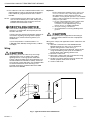
Location and Mounting
Locate the C7189 Wall Mount Temperature Sensor where
the setting will not be subjected to tampering.
1 Choose a location for the sensor on an inside wall
about 5 ft (1.5 m) above the floor. A horizontally
mounted standard 2 x 4 in. (51 x 102 mm) junction
box can also be used at the selected location for the
C7189.
2 Be sure that the wire distance between the C7189
and the W8900 does not exceed 200 feet.
3 Make sure that there is good air circulation at
average temperature at the chosen location. Avoid
the following locations because they can introduce
errors in sensor measurements. See Fig. 1:
Hot areas caused by:
• Concealed pipes or ducts.
• Drafts from fireplaces or other heat sources.
• Convection or radiant heat from the sun or
electrical equipment.
Cold areas caused by:
• Concealed pipes or ducts.
• Drafts from windows and doors.
• Unheated areas on the other side of the wall
location.
Dead air areas:
• Behind doors, furniture and curtains.
• In corners and alcoves.
4 Mark the area on the wall where the C7189 Sensor
or junction box will be mounted.
69-0895-1

69-0895—1
2
C7189A WALL MOUNT TEMPERATURE SENSOR
5 Run cable to a hole at the selected wall location. Pull
approximately 3 inches of wire through the opening.
Color-coded, 18 gauge thermostat wire is recom-
mended.
NOTE: If the old thermostat has left marks on the wall
that are not covered by the C7189, order part no.
202689A Mounting Plate Accessory to mount
between the wall and the C7189.
RECYCLING NOTICE
If this control is replacing a control that contains
mercury in a sealed tube, do not place your old
control in the trash.
Contact your local waste management authority for
instructions regarding recycling and the proper
disposal of any control containing mercury in a
sealed tube.
If you have questions, call Honeywell Inc. at
1-800-468-1502, Monday through Friday, 7:00am
to 5:30pm.
Wiring
CAUTION
Keep wiring at least one foot away from large
inductive loads such as motors, line starters,
lightning ballasts, and large power distribution
panels. Failure to follow these wiring practices can
introduce electrical interference (noise), which can
cause erratic system operation. Use shielded cable
to reduce interference when rerouting is not
possible. Ground the shielded cable to the GND
terminal on the W8900.
Important
Erratic temperature readings from a sensor can
occur as a result of any of the wiring practices
described below. These practices must be
avoided to assure proper operation. Use shielded
cable to reduce interference if rerouting of sensor
wiring is not possible.
a. Do not route temperature sensor wiring with
building power wiring, next to control
contactors or near light dimming circuits,
electric motors or welding equipment.
b. Avoid poor wiring connections.
c. Avoid intermittent or missing building earth
ground.
CAUTION
Disconnect power supply before connecting to
wiring to prevent electrical shock or equipment
damage.
Wiring must comply with applicable codes, ordinances and
regulations.
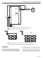
1 Wire the C7189 Sensor to the W8900 Remote
Module terminals S1 and S. For an example of
general wiring of the C7189, see Fig. 2.
2 Push excess wire back into the hole. Plug the hole
using nonhardening caulk, putty or insulation to
prevent drafts from affecting performance.
3 Remove C7189 cover.
4 Mount the C7189 to the wall or junction box using
the screws and anchors provided.
5 Level the C7189 for appearance only. Device will
function properly even when not level.
6 Install C7189 cover.
5 FEET
(1.5 METERS)
YES
NO
NO
NO
M4476
Fig. 1. Typical Location for C7189 Sensor.

69-0895—1
3
C7189A WALL MOUNT TEMPERATURE SENSOR
M4456
W8900
C7189 C7189
W8900
C7189 C7189
C7189 C7189
C7189 C7189
C7189
C7189
C7189 C7189 C7189
4
1
2
3
2
3
4
4
SENSORS MUST BE ARRANGED IN THIS NUMBER AND CONFIGURATION FOR PROPER OPERATION.
S1
S
LED
L1
(HOT)
L2
1
POWER SUPPLY. PROVIDE DISCONNECT MEANS AND OVERLOAD PROTECTION AS REQUIRED.
IF MORE THAN ONE C7189 REMOTE SENSOR IS REQUIRED, REFER TO FIGURE BELOW.
IF SHIELDED CABLE IS REQUIRED, GROUND TO GND TERMINAL ON W8900.
GND
C
R
RH
RC
C7189
W8900
S1
S
S1
S
Fig. 2. Wiring Diagram for the C7189 Sensor to the W8900 Remote Module.
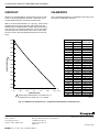
OPERATION
The C7189 Wall Mount Temperature Sensor converts
room temperature to a resistance that the controller can
interpret. The C7189 has a negative temperature coeffi-
cient (NTC), which means that the resistance decreases
as the temperature increases. Fig. 3 shows how sensor
resistance decreases by 19 ohms per degree Fahrenheit.
The C7189 can be used to control as one remote sensor,
as a temperature averaging network with the PC8900, or
with multiple C7189 Sensors connected as shown in Fig. 2.

69-0895—1
4
C7189A WALL MOUNT TEMPERATURE SENSOR
Home and Building Control
Honeywell Limited-Honeywell Limitée
740 Ellesmere Road
Scarborough, Ontario
M1P 2V9
QUALITY IS KEY
Helping You Control Your World
69-0895—1 J.H. Rev. 5-95 Printed in Mexico
CHECKOUT
Allow the C7189 Wall Mount Temperature Sensor to soak
in the air moving through the room for a minimum of five
minutes before taking a resistance measurement.
With an accurate thermometer (±1°F [0.5°C]), measure the
temperature at the sensor location, allowing time for the
thermometer to stabilize before reading. Remove one wire
from one of the C7189 wiring terminals. Use an ohmmeter
to measure the resistance across the sensor. Then verify
sensor accuracy with the temperature/resistance curve of
Fig. 3.
CALIBRATION
The C7189 Remote Sensor is calibrated at the factory and
cannot be recalibrated in the field.
Home and Building Control
Honeywell Inc.
1985 Douglas Drive
Golden Valley, MN 55422
Fig. 3. C7189 Sensor Resistance vs. Temperature Performance Characteristics.
OHM RESISTANCE
°F
(°C )
M6357
RESISTANCE DECREASES 18.6 OHMS PER 1°F
CHANGE OR 33.4 OHMS PER 1°C CHANGE.
1
1
2000
2100
1900
1500
1600
1700
1800
1400
TEMPERATURE
40
(4)
50
(10)
60
(16)
70
(21)
80
(27)
90
(32)
100
(38)
1300
1000
1200
2200
2300
46
48
50
52
54
56
58
60
62
64
66
68
70
72
74
76
78
80
82
84
86
88
90
92
94
96
98
100
7.8
8.9
10.0
11.1
12.2
13.3
14.4
15.6
16.7
17.8
18.9
20.0
21.1
22.2
23.3
24.4
25.6
26.7
27.8
28.9
30.0
31.1
32.2
33.3
34.4
35.6
36.7
37.8
2131 to 2094
2094 to 2057
2057 to 2019
2019 to 1982
1982 to 1945
1945 to 1908
1908 to 1871
1871 to 1833
1833 to 1796
1796 to 1759
1759 to 1722
1722 to 1685
1685 to 1647
1647 to 1610
1610 to 1573
1573 to 1536
1536 to 1499
1499 to 1461
1461 to 1424
1424 to 1387
1387 to 1350
1350 to 1313
1313 to 1275
1275 to 1238
1238 to 1201
1201 to 1164
1164 to 1127
1127 to 1089
ROOM TEMPERATURE
OHMS OF
RESISTANCE
°F °C
-
 1
1
-
 2
2
-
 3
3
-
 4
4


Honeywell C7189A User manual
- Type
- User manual
- This manual is also suitable for
Ask a question and I''ll find the answer in the document
Finding information in a document is now easier with AI
Related papers
-
Honeywell Thermostat perfect climate comfort center control system User manual
-
-
Honeywell VisionPro User manual
-
-
-
-
-
-
-
Honeywell C7089U1006 User manual
Other documents
-
Lennox Outdoor Temperature Sensor (X4148) Installation guide
-
Allen-Bradley 2094-BL50S Installation Instructions Manual
-
LG Electronics 20LS7D(C)-UB User manual
-
Bryant 580f User manual
-
-
Trane Model Q User manual
-
FARGO electronic Digital Audio Board 7KDAB User manual
-
-
Trane IntelliPak SXHF C50 User manual
-
Toro Dingo 222 Compact Utility Loader User manual