2
Operating instructions
Pull-wire emergency-stop switches ZQ 900
EN
1.7 Exclusion of liability
We shall accept no liability for damages and malfunctions resulting from
defective mounting or failure to comply with this operating instructions
manual. The manufacturer shall accept no liability for damages
resulting from the use of unauthorised spare parts or accessories.
For safety reasons, invasive work on the device as well as arbitrary
repairs, conversions and modifications to the device are strictly
forbidden; the manufacturer shall accept no liability for damages
resulting from such invasive work, arbitrary repairs, conversions and/or
modifications to the device.
2. Product description
2.1 Ordering code
This operating instructions manual applies to the following types:
ZQ 900-
➀➁
No. Option Description
➀
11 1 NO contact / 1 NC contact
13 1 NO contact / 3 NC contacts
22 2 NO contacts / 2 NC contacts
02 2 NC contacts
04 4 NC contacts
➁
without emergency-stop button
N with emergency-stop button
Only if the information described in this operating instructions
manual are realised correctly, the safety function and therefore
the compliance with the Machinery Directive is maintained.
2.2 Special versions
For special versions, which are not listed in the order code below 2.1,
these specifications apply accordingly, provided that they correspond to
the standard version.
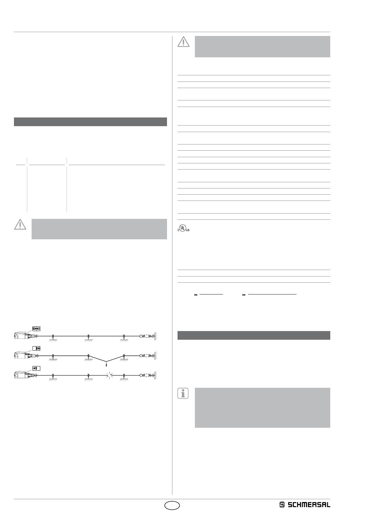
2.3 Destination and use
Pull-wire emergency stop switches are used on machinery and plants,
where triggering the emergency stop command must be enabled at
arbitrary points on the wire run. If the tensioned pull-wire is pulled or
in case of wire breakage or if the optional emergency stop switch is
pushed, the switching function of the pull-wire emergency stop switch is
activated. (refer to image 1).
F
1
Image 1: position indication and actuation
Design/operating principle
The pull-wire emergency stop switches of the ZQ 900 series are
brought into the operational condition by the proper pre-tensioning
of the wire. Up to two switching elements located on the inside of the
switch have either 2 or 4 contacts, whereby the NC contacts are closed
and the NO contacts are opened in tensioned condition.
After actuation of the emergency stop function, a latching mechanism
maintains the stop command until the switch is released by pushing
the blue reset button. Prior to the reset of the emergency stop signal,
the reason why the switch has been actuated must be determined. The
switch can only be reset if the switch is correctly pre-tensioned (position
indication in central position, refer to image 1).
The entire concept of the control system, in which the safety
component is integrated, must be validated to the relevant
standards.
2.4 Technical data
Standards: IEC 60947-5-1, IEC 60947-5-5, ISO 13850
Enclosure: GD-Zn alloy, paint
Cover: thermoplastic
Protection class: IP65, IP67 to IEC 60529
- ZQ 900-...-N: IP65
Contact material: Silver
Switching system: Change-over contact with double break,
1 to 4 NC contacts; snap action
with positive break NC contacts
Connection: screw terminals
Cable section: max. 2.5 mm²
(incl. conductor ferrules)
Cable entry: 3 x M20x1,5
Rated impulse withstand voltage Uimp: 6 kV
Rated insulation voltage Ui: 500 V
Thermal test current Ithe: 6 A
Rated operating current/voltage Ie/Ue: 4 A / 230 VAC,
1 A / 24 VDC
Utilisation category: AC-15, DC-13
Max. fuse rating: 6 A gG D-fuse (EN 60269-1)
Ambient temperature: –25 °C … +70 °C
Wire length: max. 75 m depending in relation to the
range of ambient temperature (see image 3)
Mechanical life: >1 million operations
Input terminal wire size AWG: 14-22
Max. Torque: 7 Lb In
Use solid or stranded copper conductors only.
2.5 Safety classification
Standards: ISO 13849-1
B10D NC contact: 100,000
Service life: 20 years
TF
D
10Dopop
op
n
(Specifications can vary depending on the application-specific
parameters hop, dop and tcycle as well as the load.)
3. Mounting
3.1 General mounting instructions
The installation may only be carried out by authorised personnel.
The pull-wire emergency stop switch is fitted by means of two screws
(distance of the drill holes 40 mm or 48 mm), so that a release by hand
can be realised without hazard. The component must be fitted so that the
entire length of the wire can be viewed from the position of the switch.
In accordance with IEC 60947-5-5, the maximum
perpendicular traction force to be exercised on the wire
in order to activate the emergency pull-wire switch is
200 N, the maximum deflection is 400 mm. Sufficient
space must be provided so that the required actuating
deflection can be reached.
For tensioned span lengths up to 10 m, intermediate wire supports
are required every 3 to 5 m. To avoid resonance vibrations in the wire
on machines with high vibrations, it is recommended to realise the
individual support length differently. Assembly: refer to image 2.


