schmersal EX-ZQ 900-13-3D Operating instructions

Type
Operating instructions
EX-ZQ 900-…-3D
Operating instructions
Pull-wire emergency stop switches
EN 1
1. About this document
1.1 Function
This operating instructions manual provides all the information you
need for the mounting, set-up and commissioning to ensure the safe
operation and disassembly of the safety switchgear. The operating
instructions must be available in a legible condition and a complete
version in the vicinity of the device.
1.2 Target group: authorised qualified personnel
All operations described in this operating instructions manual must
be carried out by trained specialist personnel, authorised by the plant
operator only.
Please make sure that you have read and understood these operating
instructions and that you know all applicable legislations regarding
occupational safety and accident prevention prior to installation and
putting the component into operation.
The machine builder must carefully select the harmonised standards
to be complied with as well as other technical specifications for the
selection, mounting and integration of the components.
1.3 Explanation of the symbols used
Information, hint, note:
This symbol indicates useful additional information.
Caution: Failure to comply with this warning notice could
lead to failures or malfunctions.
Warning: Failure to comply with this warning notice could
lead to physical injury and/or damage to the machine.
1.4 Appropriate use
The Schmersal range of products is not intended for private consumers.
The products described in these operating instructions are developed
to execute safety-related functions as part of an entire plant or machine.
It is the responsibility of the manufacturer of a machine or plant to
ensure the correct functionality of the entire machine or plant.
The safety switchgear must be exclusively used in accordance with
the versions listed below or for the applications authorised by the
manufacturer. Detailed information regarding the range of applications
can be found in the chapter "Product description".
1.5 General safety instructions
The user must observe the safety instructions in this operating
instructions manual, the country specific installation standards as well
as all prevailing safety regulations and accident prevention rules.
Further technical information can be found in the Schmersal
catalogues or in the online catalogue on the Internet:
products.schmersal.com.
The information contained in this operating instructions manual is
provided without liability and is subject to technical modifications.
There are no residual risks, provided that the safety instructions as well
as the instructions regarding mounting, commissioning, operation and
maintenance are observed.
1.6 Warning about misuse
In case of improper use or manipulation of the safety
switchgear, personal hazards or damages to machinery or
plant components cannot be excluded.
Content
1 About this document
1.1 Function ..............................................1
1.2 Target group: authorised qualied personnel..................1
1.3 Explanation of the symbols used ...........................1
1.4 Appropriate use ........................................1
1.5 General safety instructions ...............................1
1.6 Warning about misuse ...................................1
1.7 Exclusion of liability .....................................2
2 Product description
2.1 Ordering code .........................................2
2.2 Special versions........................................2
2.3 Purpose ..............................................2
2.4 Design/operating principle ................................2
2.5 Technical data .........................................2
2.6 Safety classication ....................................2
3 Mounting
3.1 General mounting instructions .............................3
3.2 Dimensions ...........................................4
4 Electrical connection
4.1 General information for electrical connection..................4
4.2 Contact Options ........................................4
5 Set-up and maintenance
5.1 Functional testing.......................................4
5.2 Maintenance ..........................................4
6 Disassembly and disposal
6.1 Disassembly...........................................4
6.2 Disposal ..............................................4
7 EU Declaration of conformity
x.000 / 06.2023 / v.A. - 101212127-EN / F / 2023-05-05 / AE-Nr. 10555
EN Operating Instructions . . . . . . . . . . . .pages 1 to 6
Original
2
Operating instructions
Pull-wire emergency stop switches EX-ZQ 900-…-3D
EN
1.7 Exclusion of liability
We shall accept no liability for damages and malfunctions resulting from
defective mounting or failure to comply with this operating instructions
manual. The manufacturer shall accept no liability for damages
resulting from the use of unauthorised spare parts or accessories.
For safety reasons, invasive work on the device as well as arbitrary repairs,
conversions and modifications to the device are strictly forbidden, the
manufacturer shall accept no liability for damages resulting from such invasive
work, arbitrary repairs, conversions and/or modifications to the device.
2. Product description
2.1 Ordering code
This operating instructions manual applies to the following types:
EX-ZQ 900-
-3D
No. Option Description
11 1 NO / 1 NC
13 1 NO / 3 NC
22 2 NO / 2 NC
02 2 NC
04 4 NC
Only if the information described in this operating instructions
manual are realised correctly, the safety function and
therefore the compliance with the Machinery Directive and
the Explosion Protection Directive is maintained.
2.2 Special versions
For special versions, which are not listed in the order code below 2.1,
these specifications apply accordingly, provided that they correspond to
the standard version.
2.3 Purpose
Pull-wire emergency stop switches are used on machinery and plants in
explosion-endangered areas of Zone 22 equipment category 3D, where
triggering the emergency stop command must be enabled at arbitrary
points on the wire run.
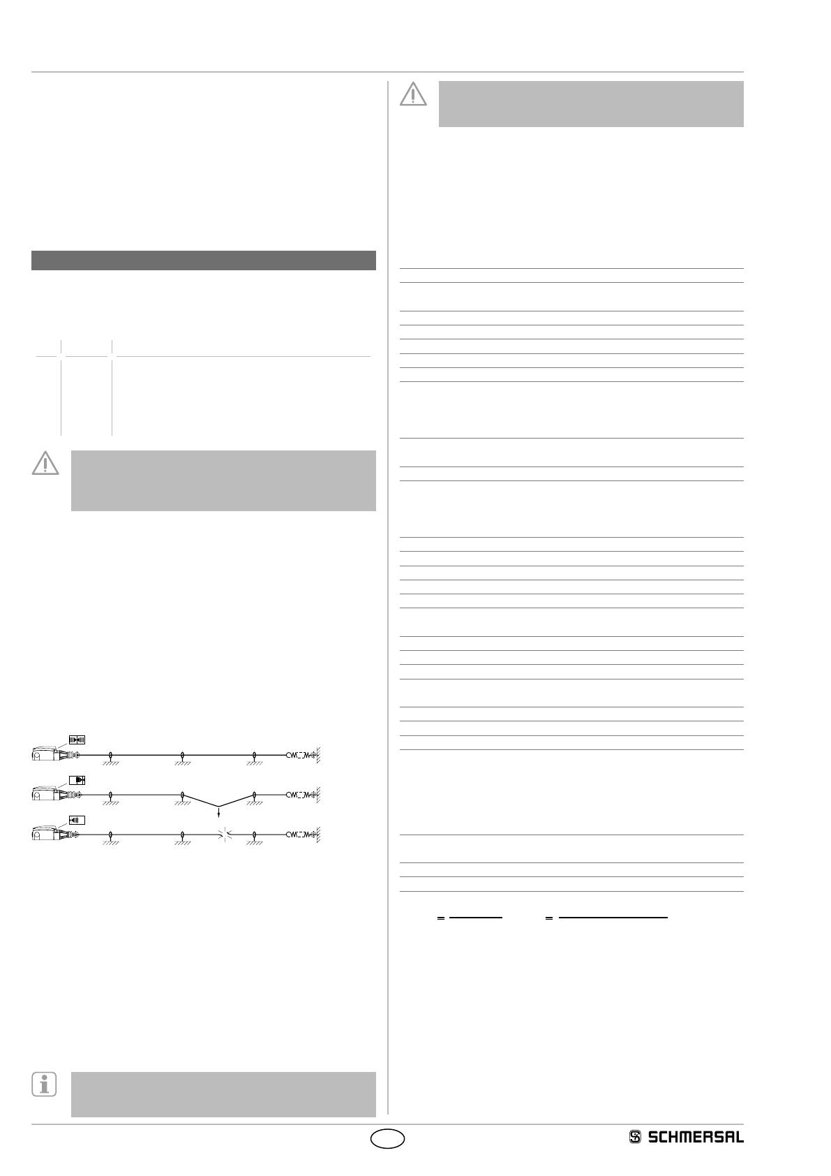
If the tensioned pull-wire is pulled or in case of wire breakage, the
switching function of the pull-wire emergency stop switch is activated
(refer to image 1).
F
1
0
0
Image 1: Position indication and actuation
2.4 Design/operating principle
The pull-wire emergency stop switches are brought into the operational
condition by the proper pre-tensioning of the wire. Up to two switching
elements located on the inside of the switch have either 2 or 4 contacts,
whereby the NC contacts are closed and the NO contacts are opened
in tensioned condition.
After actuation of the emergency stop function, a latching mechanism
maintains the stop command until the switch is released by pushing
the blue reset button. Prior to the reset of the emergency stop signal,
the reason why the switch has been actuated must be determined. The
switch can only be reset if the switch is correctly pre-tensioned (position
indication in central position, refer to image 1).
The user must evaluate and design the safety chain in
accordance with the relevant standards and the required
safety level.
The entire concept of the control system, in which the safety
component is integrated, must be validated to the relevant
standards.
Conditions for safe operation
The specific ambient temperature range must be observed. The user
must provide for a protection against the permanent influence of UV rays.
The installation and maintenance requirements to the standard series
60079 must be met.
2.5 Technical data
Marking in accordance with the ATEX Directive:
D
II 3GD
Marking in accordance with standards: Ex tc IIIC T100°C Dc
Applied standards: EN 60947-5-1, EN 60947-5-5, EN ISO 13850,
EN 620, EN IEC 60079-0, EN 60079-31
Enclosure: zinc die-cast, enamel finish
Cover: Steel
Degree of protection: IP67 to EN 60529
Contact material: Silver
Max. impact energy: 7 J
Contact type: 1 NC / 1 NO or
2 NC / 2 NO or
3 NC / 1 NO or
2 NC or 4 NC
Switching system:
B
EN 60947-5-1 snap action,
NC contacts with positive break
Connection: screw terminals
Cable section:
- solid wire: 0.75 … 2.5 mm²
- stranded wire: 0.75 … 2.5 mm²
with conductor ferrules
Cable entry: 3 × M20
Rated impulse withstand voltage Uimp: 6 kV
Rated insulation voltage Ui: 500 V
Thermal test current Ithe: 4 A
Utilisation category: AC-15 / DC-13
Rated operating current/voltage Ie/Ue: 4 A / 230 VAC
1 A / 24 VDC
Max. fuse rating: 6 A gG D-fuse to EN 60269-1
Ambient temperature: −20 °C … +55 °C
Mechanical life: max. 1 million operations
Wire length: max. 75 m depending in relation to the
range of ambient temperature (see image 4)
Features: wire pull and breakage detection
Cable cross-section of the EX cable glands: Ø 7 … 12 mm
Ex cable gland:
D
II 2GD
Tightening torque:
- Ex cable gland: 10 Nm
- Ex locking screw: 8 Nm
- Cover screws: 0.6 … 0.9 Nm
- Earth screws: PE 1 Nm
PA 1.2 Nm
2.6 Safety classification
Standards: EN ISO 13849-1
B10D NC: 100,000
Mission time: 20 years
MT
TF
Bdxx
hs/h3600
D
10Dopop
op
n
0,1 x nop tcycle
(Determined values can vary depending on the application-specific
parameters hop, dop and tcycle as well as the load.)
If multiple safety components are wired in series, the Performance
Level to EN ISO 13849-1 will be reduced due to the restricted error
detection under certain circumstances.
3
EX-ZQ 900-…-3D
Operating instructions
Pull-wire emergency stop switches
EN
3. Mounting
3.1 General mounting instructions
The installation may only be carried out with the system
de-energised and by authorised personnel.
The pull-wire emergency stop switch is fitted by means of two screws
(distance of the drill holes 40 mm or 48 mm).
The device must be arranged so that unlocking by hand is
entirely without risk and that the entire length of the wire can
be seen from the switch.
Please observe the information on tightening torques in the
technical data.
In accordance with EN 60947-5-5 (EN 620), the maximum
perpendicular traction force to be exercised on the wire in
order to activate the emergency pull-wire switch is 200 N
(125 N), the maximum deflection is 400 mm (300 mm).
Sufficient space must be provided so that the required
actuating deflection can be reached. It must be ensured that
when tensioned, the wire rope always follows a straight course
and that it remains in the correct position at all times (including
at the redirection point). External influences (temperature
variations, ageing) can affect the properties of the wire rope.
The information in EN ISO 13850 must be observed.
For lengths of over 10 m, intermediate wire supports must be
installed after max. 3 m. To avoid resonance vibrations in the wire
on machines with high vibrations, it is recommended to realise the
individual support length dierently. Assembly: refer to image 2.
64 23 65 61
0,1 m
3 m
A
B
46 932
max. 75 m
8238327
0,1 m
3 m
A
1 9
B
Image 2: Mounting of the components
Key
A
B
Position indicator
Reset button
1 Pull-wire with red PVC jacket,
Ø 5 mm (steel core: Ø 3 mm)
2 Eyebolt
3 Nut
4 Wire clamp
5 Tensioner
6 Wire thimble
7 Shackle
8 Wire tensioner S900
9 Tension spring ACC-RS900-TS
We recommend the use of the ACC-RS900-TS tension spring to reduce
the effects of temperature variations.
Due to the thermal expansion behaviour of the wire, the maximum
authorised wire length is determined by the ambient temperature range
(refer to image 4).
In order to ensure an optimal operation safety and to save
time during fitting, we recommend using the wire rope and
the combined fixing and tensioning system from Schmersal.
Alternatively, wire thimbles and wire clamps can be used in
conjunction with a tensioner. In this case, the red PVC sheet
must be removed in the clamp area prior to installing the wire
rope.
As the thimbles are subject to deformation in case of wire pull, the wire
should be pulled several times after fitting. After that, the wire must be
re-tensioned (see image 3).
Image 3: Thimble deformation
Correct operation of the product is directly connected to the data
shown in the diagram. The maximum wire length depends on the
temperature change to which the hauling wire system is exposed. The
corresponding wire length with and without external tension spring is
shown in the diagram.
354045
5
15
25
35
4
5
55
65
75 lm[]
[]
30 25 20 15 10 5x 35 40 4530252015105 Kdt
x Reference temperature
■
without tension spring
■
with tension spring
Image 4: Temperature-dependent maximum wire length with or without
tension spring
The pull-wire must be fixed to the ring and then be pre-tensioned until
the position indication is in the central position (refer to image 1).
4
Operating instructions
Pull-wire emergency stop switches EX-ZQ 900-…-3D
EN
3.2 Dimensions
All measurements in mm.
EX-ZQ 900
48
40
27
71
B
A
57
72
Ø6.5
134
10
12
221-237
Ø32.7
M20x1.5
11
71.5
30 22
Ø16
Legend:
A = Position indication
B = Reset-button
4. Electrical connection
4.1 General information for electrical connection
The electrical connection may only be carried out by
authorised personnel in a de-energised condition.
Only use EX cable glands which are authorised for the
corresponding field of application.
The cable glands must be fitted in accordance with the
applicable operating instructions manual. Cable glands are
only authorised for permanent cables. The constructor must
provide for the necessary strain relief.
Ununused cable entries must be sealed by means of Ex
approved locking screws. Cable gland and locking screws are
included in the delivery.
1. Cover screws must be loosened
2. Dust shield cap remove
3. Use Ex cable gland M20 x 1.5 (included in delivery).
4. When wiring, please ensure that no cables are located within the
range of the lever system and the pushbutton
5. The inside of the switch must be imperatively cleaned (e.g. removal
of cable residues), considering that foreign bodies can affect the
switching behaviour
6. Unused cable entries must be sealed by means of Ex locking screws
(Tightening torque 8 Nm)
7. The cover screws must be tightened uniformly
(tightening torque 0.6 … 0.9 Nm)
Settle length x of the conductor:
- on screw terminals: 6 mm
- on the protective conductor terminal: 5 mm
XX
The external protective conductor terminal is to be connected
in accordance with EN 60079-14 section 6.3.
A ring cable lug of size M5 must be used for connection of the
conductor.
4.2 Contact Options
Contacts shown in a de-energised condition.
EX-ZQ 900-11-3D EX-ZQ 900-02-3D EX-ZQ 900-13-3D
14
13
22
21
12
11
22
21
11 12
2221
14
13
2221
S1 S2
EX-ZQ 900-22-3D EX-ZQ 900-04-3D
13 14
2221
14
13
2221
S1 S2
11 12
2221
12
11
2221
S1 S2
Key
B
Positive break NC contact
5. Set-up and maintenance
5.1 Functional testing
The safety function of the safety components must be tested.
The following conditions must be previously checked and met:
1. Check the correct fitting of the pull-wire emergency stop switch
2. Check cable entry and connections in a de-energised condition
3. Check the switch enclosure for damage
4. Check the functionality of the switch by actuating the wire
5. Check the cable tensioning by means of the position indicator
5.2 Maintenance
In case of correct installation in accordance with the above-described
instructions, the component requires little maintenance. For use in
extreme conditions, we recommend routine maintenance including the
following steps:
1. Check the correct fitting of the pull-wire emergency stop switch
2. Check the functionality of the switch by actuating the wire
3. Check cable entry and connections in a de-energised condition
4. Remove particles of dust and soiling
5. Check the wire tension through the wire position indication and check
the wire and the wire guides for damages and proper fitting
Do not open the device under tension.
For explosion protection reasons, the component must be
exchanged after max. 1 million operations.
Damaged or defective components must be replaced.
6. Disassembly and disposal
6.1 Disassembly
The safety switchgear must be disassembled in a de-energised
condition only.
6.2 Disposal
The safety switchgear must be disposed of in an appropriate
manner in accordance with the national prescriptions and legislations.
5
EN
EX-ZQ900-3D-E-EN
EX-ZQ 900-…-3D
Operating instructions
Pull-wire emergency stop switches
7. EU Declaration of conformity
Place and date of issue: Wuppertal, June 15, 2023
Authorised signature
Philip Schmersal
Managing Director
EU Declaration of conformity
Original K.A. Schmersal GmbH & Co. KG
Möddinghofe 30
42279 Wuppertal
Germany
Internet: www.schmersal.com
We hereby certify that the hereafter described components both in their basic design and construction conform
to the applicable European Directives.
Name of the component: EX-ZQ 900-…-3D
Type: see ordering code
Marking:
D
II 3D Ex tc IIIC T100°C Dc
Description of the component: Pull-wire emergency stop switch with safety function
Relevant Directives: Machinery Directive
Explosion Protection Directive (ATEX)
RoHS-Directive
2006/42/EC
2014/34/EU
2011/65/EU
Applied standards: EN 60947-5-1:2017 + AC:2020
EN 60947-5-5:1997 + A1:2005 + A11:2013 + A2:2017
EN 620:2002 + A1:2010
EN ISO 13850:2015
EN IEC 60079-0:2018
EN 60079-31:2014
Person authorised for the compilation
of the technical documentation:
Oliver Wacker
Möddinghofe 30
42279 Wuppertal
Conformity with the explosion protection directive 2014/34/EU (ATEX) is declared by the manufacturer
without involving a conformity assessment center.
The currently valid declaration of conformity can be
downloaded from the internet at products.schmersal.com.
K.A. Schmersal GmbH & Co. KG
Möddinghofe 30, 42279 Wuppertal
Germany
Phone: +49 202 6474-0
Telefax: +49 202 6474-100
Internet: www.schmersal.com
  • Page 1 1
  • Page 2 2
  • Page 3 3
  • Page 4 4
  • Page 5 5
  • Page 6 6

schmersal EX-ZQ 900-13-3D Operating instructions

Type
Operating instructions

Ask a question and I''ll find the answer in the document

Finding information in a document is now easier with AI