Ridetech 11290202 Installation guide

Type
Installation guide

Ridetech 11290202 is a high-performance suspension system designed to enhance the handling and ride quality of 1965-1966 GM B-Body vehicles. Featuring tubular control arms, coilover shocks, and a rear sway bar, this system provides improved stability, cornering, and braking capabilities. The coilover shocks allow for precise ride height adjustment and feature a 3.6-inch stroke for increased suspension travel. The tubular control arms are built with durable steel construction and offer improved strength and rigidity over stock components.

Ridetech 11290202 is a high-performance suspension system designed to enhance the handling and ride quality of 1965-1966 GM B-Body vehicles. Featuring tubular control arms, coilover shocks, and a rear sway bar, this system provides improved stability, cornering, and braking capabilities. The coilover shocks allow for precise ride height adjustment and feature a 3.6-inch stroke for increased suspension travel. The tubular control arms are built with durable steel construction and offer improved strength and rigidity over stock components.

1812-482-2932
Installation
Instructions
Recommended Tools
www.ridetech.com
Part # 11290302 - 1965-1966 GM “B” Body TQ CoilOver System
Front Components:
11282899 Front Lower StrongArms
11283699 Front Upper StrongArms
11283511 Front CoilOver Instructions
11289100 Front SwayBar Instructions
Rear Components:
11286211 Rear CoilOver Kit Includes:
Rear Lower StrongArms
Rear CoilOvers
11296698 Rear Upper StrongArms
11289000 Adjustable Panhard Bar
Miscellaneous Components:
85000000 Spanner Wrench
1965-1966 GM “B” Body CoilOver
Installation Instructions
THE FRONT CONTROL ARMS ARE DESIGNED TO BE USED WITH THE OEM SPINDLES.
Some vehicles have two factory upper arms and need a second tubular arm.
65-66 B-Body Rear Upper StrongArm Kit # 11296698.
REV2 4/6/22
Table of contents
Pages 2-6............. Front CoilOvers
Pages 7-10........... Front SwayBar
Pages 11-19......... Front StrongArms
Pages 20-39......... Rear CoilOver Kit
Pages 40-44......... Rear SwayBar
2
www.ridetech.com
Installation
Instructions
Recommended Tools
www.ridetech.com
ShockWave Dimensions:
Center of Bearing to Stud Mounting Surface:
Compressed: 10.48”
Ride Height: 12.55”
Extended: 14.08”
Part # 11283511 - 1965-1970 GM “B” Body HQ Front CoilOvers
Table of contents
Page 3............ Included Components
Page 4............ CoilOver Assembly
Page 5-6......... CoilOver Installation
1965-1970 GM “B” Body TQ Series Front CoilOvers
Installation Instructions
3812-482-2932
Installation
Instructions
1
2
3
4
5
6
7
8
9
3
10
11
12
13
14
15
Major Components .....In the box
Item
#Part # Description QTY
1 982-10-803 3.6” Stroke HQ Series Shock 2
2 59080750 Coilspring 8” 750lb 2
3 70010828 Delrin Spring Washer 4
4 803-00-199(kit) Lower Spring Adjuster Nut (803-00-199 kit) 2
5 803-00-199(kit) Adjuster Nut Locking Screw (803-00-199 kit) 2
6 90002070 Dropped Upper CoilSpring Retaining Plate 2
7 803-00-199(kit) CoilSpring Plate Retaining Ring (803-00-199 kit) 2
8 90009989(kit) 2.75” Stud Adjuster Assembly 2
9 90002313 2.75” Stud Top Base 2
10 90001904 Delrin Ball Lower Half 2
11 90001903 Delrin Ball Top Half 2
12 90001902 Delrin Ball Upper Cap 2
13 99562003 9/16-18” Nylok Nut 2
14 210-35-120-0 Shock Adjuster Knob 2
15 90009969 Adjuster Knob Retaining Screw 2
90001994 5/8” ID Bearing (installed in shock body) 2
90001995 Bearing Snap Ring (installed in shock body) 4
4
www.ridetech.com
Installation
Instructions
1
2
3
5
6
7
8
9
10
5
4
1. To Assemble the CoilOver you need to:
a. Remove Screw (2) from center of Adjustment
Knob (1) and remove Adjustment Knob.
b. Remove Nylok Nut, Delrin Upper Cap, Delrin
Upper and Lower Balls, along with the base from
the CoilOver stud.
c. Thread Adjuster Nut (3) onto the CoilOver
body. Once it is threaded on the shock body,
lightly thread in the locking screw (4) into the
Adjuster Nut.
d. Install a Delrin Spring Washer (5) onto the
Adjuster Nut.
e. Slide the CoilSpring (6) onto the CoilOver.
f. Install another Delrin Spring Washer (5) on top
of the CoilSpring.
g. Install the Upper CoilSpring Plate (7) onto the
CoilSpring.
h. Install the CoilSpring Retaining Ring (8) onto
the Stud Top Base (9). It fits into the groove in
the base.
i. Slide the Stud Top Base onto the shock until it
bottoms out on the stud. It may be necessary to
thread the Adjuster Nut down the shock body (to
lower the spring) if the base will not slide all the
way down onto the stud.
k. Slide the Lower Delrin Ball (10) (it has the col-
lar sticking up around the center hole) on to the
Stud Top.
Repeat on second CoilOver.
CoilOver Assembly
1.
5812-482-2932
Installation
Instructions
CoilOver Installation
1. Drill the OEM shock hole out to 3/4”. This
can be done with a Unibit.
2. The CoilOver stud top will come in contact
with the coil spring retainer, so it must be
opened up towards the engine. Image 2
has a white line illustrating where to cut the
opening for stud top clearance. A die grinder
works well here.
3. Image 3 shows the spring retainer trimmed
out.
Note: It may be helpful to go ahead and
install the lower StrongArms and CoilOvers to
check if any more trimming is necessary.
2.
1.
3.
DRILL TO 3/4”
6
www.ridetech.com
Installation
Instructions
CoilOver Installation
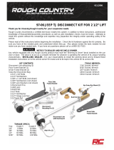
2. With the CoilOver(1) assembled, it is time
to bolt them into the car. The factory shock
hole will need to be drilled out to 3/4”, this
can best be done using a Unibit. Insert to
CoilOver Stud Top through the factory hole in
the frame. Install the Upper Delrin Ball(2) onto
the shock stud with the flat side facing the
frame. Next, Install the Delrin Ball cap (3) onto
the shock stud with the Concave side facing
the Upper Delrin ball. Install the Nylok Nut(3)
onto the shock stud and lightly tighten. The
needs to be some resistance on the ball but
not tight enough that it will not rotate freely.
Reinstall the adjuster knob(5) using the screw
(6) that was removed during step 1.
TIGHTENING THE TOP 9/16”-18 NUT: SNUG
THE NUT DOWN AGAINST THE TOP CAP. YOU
NEED TO BE ABLE TO ARTICULATE THE SHOCK
BY HAND. WE TORQUE THE NUT TO 80 INLBS
USING A 7/8” CROWS FOOT WRENCH ON A
TORQUE WRENCH.
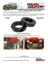
3. Install a spacer on each side of the lower
Coilover. Slide the shock with the spacers in-
stalled into the lower control arm. Raise the
arm up to line up the holes in the bushing
with the 1/2” hole in the control arm straps
and hold it in place while you install the 1/2” x
3 1/2” bolt, 1/2” flat washer, and 1/2” Nylok
nut. Tighten the upper and lower shock bolts.
2.
3.
FRAME
1
2
3
4
56
7812-482-2932
Installation
Instructions
Recommended Tools
www.ridetech.com
Table of contents
Page 8........... Included Components and Hardware List
Page 9-10..... Sway Bar Installation
Part # 11289100 - 1965-1970 B-Body Front Sway Bar
1965-1970 GM B-Body Front Sway Bar
Installation Instructions
Install this Sway bar BEFORE installing the lower control arms.
REV1 6/16/22
8
www.ridetech.com
Installation
Instructions
Major Components .....In the box
Part # Description QTY
90000104 Front Sway Bar 1
90001100 Bushing & Strap Kit 1
90000929 12mm End Link 2
90001092 Tube of Lithium Grease 1
1.
Part # Description Usage QTY
99371004 3/8”-16 x 1 1/4” Hex Bolt Bushing Mount to Frame 4
99373003 3/8” Flat washer Bushing Mount to Frame 8
99372002 3/8”-16 Nylok Nut Bushing Mount to Frame 4
99123001 M12 Lock Washer PosiLink to Sway Bar 2
99122001 M12-1.75 Nylok Nut PosiLink to Control Arm 2
99433002 7/16” Flat Washer PosiLink to Control Arm 4
Getting Started.........
Install this Sway bar BEFORE installing the lower control arms. It is very difficult to install
with the Ridetech lower control arms installed.
This sway bar is designed to be used with Ridetech StrongArms and will NOT fit the OEM control
arms.
The sway bar will need to be put in position before installing the bushings and straps
1. Slide the sway bar though the same holes
in the frame that the factory bar went through.
The sway bar needs installed with the center
dropping down toward the ground to clear the
engine.
Hardware Kit .....99010042
9812-482-2932
Installation
Instructions
Sway Bar Installation
2. Lubricate the sway bar busing with the
lithium grease supplied. Install the new
polyurethane bushing and strap over the sway
bar.
3. Clamp the sway bar up to the frame using
a couple “C” clamps. The sway bar should be
centered in the hole through the frame.
4. The factory bolt holes may not line up with
the new strap. If not, two new holes must be
drilled with a 3/8” bit. Secure the assembly
with two 3/8” x 1 ¼” bolts, flat washers and
Nylok nuts.
3.
2.
4.
10
www.ridetech.com
Installation
Instructions
Sway Bar Installation
Install the lower StrongArms.
5. Screw one end of the PosiLink into the end
of the sway bar. A 12mm lock washer will be
used between the stud and the sway bar.
6. The other end of the PosiLink will attach to
the tab on the StrongArm using a flat washer
on each side of the tab and M12-1.75 nylok
nut.
6.
5.
8. Tighten all hardware. 3/8” hardware gets torqued to 30 ft-lbs. M12 gets hardware gets torqued to 65
ft-lbs.
8. Check sway bar clearance through full suspension travel.
11 812-482-2932
Installation
Instructions
Recommended Tools
www.ridetech.com
Table of contents
Page 12.............. Lower Control Arm Components
Page 13.............. Getting Started & Installation
Page 14-15......... Control Arm Installation
1965-1970 GM B-Body Front Lower StrongArms
1965-1970 GM B-Body Lower StrongArms
Installation Instructions
Part # 11282899
Note: This kit is designed for use with our MuscleBar sway bar. It is easier to install it before the lower
arms. The factory sway bar will not fit.
12
www.ridetech.com
Installation
Instructions
Lower Control Arm Components .....In the box
Driver Side Shown
10
4
5
7
12
9
11
14
13
3
1
2
616
8
15
18
17
Item # Part Number Description QTY
1 90000093 Driver Lower Control Arm (Shown) 1
1 90000094 Passenger Lower Control Arm 1
2 90002586 Lower Ball Joint Assembly - only available through Ridetech 2
3 90000928 Control Arm Bushing 2
4 90000732 Bearing Stud 2
5 90000734 Bearing Housing 2
6 90000735 Bearing Retaining Plate 2
7 90001045 Control Arm Pivot Bearing 2
8 90000733 Pivot Bearing Spacer 2
9 99752006 3/4”-16 Jam Nut 2
10 90002062 ShockWave/CoilOver Bearing Spacers 4
11 99372004 3/8”-16 Hex Nut 2
12 99371004 3/8”-16 x 1 1/4” Hex Bolt 2
13 99501005 1/2”-13 x 3 1/2” Hex Bolt 2
14 99502009 1/2”-13 Nylok Nut 2
99503014 1/2” SAE Flat Washer 4
15 99371018 3/8”-16 x 1 1/4” SHCS 6
16 99373006 3/8” Split Lock Washer 6
17 99752001 3/4”-16 Lock Nut 2
18 99753002 3/4” Flat Washer 2
13 812-482-2932
Installation
Instructions
Getting Started.........
Congratulations on your purchase of the Ridetech B-Body StrongArms. These StrongArms have been
designed to give your B-Body excellent handling along with a lifetime of enjoyment. Some of the key
features of the StrongArms: Ball Joint angles have been optimized for the lowered ride height. The
Geometry has been optimized for excellent handling, and drive ability. The control arm is a 1-piece control
arm to eliminate the strut rod and bushing.
Note: These control arms are designed for use with the Ridetech ShockWaves or CoilOvers and the
MuscleBar swaybar. The factory shocks and springs or the factory sway bar will not fit these arms.
Installation
4.
4. The control arms are marked “D” for
Driver and “P” for Passenger. The ball joint pin
points down and the sway bar mount is on the
front side of the arm.
DRIVER
1. Raise and support vehicle at a safe, comfortable working height. Let the front suspension hang freely.
2. Remove the coil spring, shock absorber, upper and lower control arms, sway bar and the strut rods. The
factory lower control arm bolt will be reused.
Note: This kit is designed for use with our MuscleBar sway bar. It is easier to install it before the lower
arms. The factory sway bar will not fit.
3. Drill the factory upper shock mounting hole to 3/4”. This can be done easily with a Unibit.
Attach the CoilOver/ShockWave to the frame before installing the lower control arm.
Suggested Alignment Specs:
Camber: Street: -.5 degrees
Caster: Street: +3.0 to + 5.0 degrees
Toe: Street: 1/16” to 1/8” toe in
14
www.ridetech.com
Installation
Instructions
Control Arm Installation
5. Using the bearing retainer as a template;
drill three 3/8” holes in the frame to secure the
assembly. Use three 3/8” x 1 ¼” SHCS and lock
washers to secure the assembly. Torque to 30
ft-lbs.
Note: The hole in the frame may need to be
buffed to allow bearing assembly to slide in.
6. Insert the front leg of the control arm
into the frame swivel bearing. Bolt the lower
StrongArm to the frame using the factory bolt.
The lower control arm pivot bolt gets
torqued to 100-125 ft-lbs when the car is
sitting on the ground.
7. The front leg of the lower arm will attach
to the frame in place of the strut rod. Refer
to Diagram 7 for assembly order. Torque the
3/4”-16 nut to 75 ft-lbs.
6.
7.
5.
15 812-482-2932
Installation
Instructions
Control Arm Installation
8. Insert the bearing spacers into the lower
shock bearing. The SMALL end goes into the
bearing. Swing the control arm up, line up
the 1/2” holes with the bearing spacers, insert
1/2”-13 x 3 1/2” bolt. Install a 1/2” flat washer
and nylok nut. Torque to 75 ft-lbs.
9. Attach the spindle to the control arms.
Torque Specs:
Lower Ball joint - 70 ft-lbs and tighten to line
up cotter pin.
Install the cotter pin after tightening the ball
joint nut.
10. Thread the 3/8”-16 nut onto the 3/8”-16
x 1 ¼” bolt. Thread it into the front hole of
the ball joint plate. You will need to adjust the
steering stop to suite your needs. This setting
will vary depending on wheel and tire size and
other suspension components. Torque to 16
ft-lbs.
9.
10.
8.
16
www.ridetech.com
Installation
Instructions
Recommended Tools
www.ridetech.com
Part # 11283699 - 1965-1970 GM B-Body Front Upper StrongArms
1965-1970 GM B-Body Upper StrongArms
Installation Instructions
THESE CONTROL ARMS ARE DESIGNED TO BE USED WITH THE OEM SPINDLES.
REV2 10/30/20
Table of contents
Page 17......... Upper Control Arm Components
Page 18......... Getting Started & Installation
Page 19......... Installing Spindle and Alignment
17 812-482-2932
Installation
Instructions
46
4
5
6
7
88
3
1
2
5
7
Upper Control Arm Components .....In the box
Driver Side Shown
Item
#Part Number Description QTY
1 90001296 Driver Upper Control Arm (Shown) 1
1 90001297 Passenger Upper Control Arm 1
2 90000905 kit Upper Ball Joint Kit - Proforged # 101-10038 2
3 90000102 Cross Shaft 2
4 90001442 Delrin Bushing 4
5 90001290 Delrin Bushing Inner Sleeve 4
6 99373001 Outer Washer - Cross Shaft 4
7 99373005 3/8” Split Lock Washer -Cross Shaft 4
8 99371013 3/8”-24 x 1” Hex Bolt - Cross Shaft 4
18
www.ridetech.com
Installation
Instructions
Getting Started.........
Congratulations on your purchase of the Ridetech StrongArms. These StrongArms have been designed
to give your car excellent handling along with a lifetime of enjoyment. Some of the key features of the
StrongArms: Ball joint angles have been optimized for the lowered ride height, Delrin bushings are used
to eliminate bushing deflection along with providing free suspension movement through the entire travel.
The Delrin bushings are made from a material that is self lubricating so no grease zerks are needed.
When assembling the Control Arms tighten the cross shaft bolts enough to create
drag on the delrin bushings, the arm should still move through its travel by hand.
Installation
1. Remove the upper control arms from the car. Keep the shims separate so that you can put them back
in the location they were removed from. If you are replacing the lower control arms and spindle, remove
them too. Refer to a Factory Service Manual for the proper method.
2.
Driver Side
Top View
2. 2. Insert the Ball Joint into the Control Arm
from the TOP side with the Stud pointing
downward. Insert the supplied Bolts from the
top side. Install a Lock Washer and Hex Nut on
the threads of each bolt. Torque the hardware
to 18 ftlbs.
3. The Upper Control Arm is attached to the
factory frame using factory hardware. The
driver side arm is shown in Figure “3”. The
Ball joint is located on the arm to the REAR of
the car.
19 812-482-2932
Installation
Instructions
Installing Spindle and Alignment
4. The Upper Control Arm is attaching
the factory mount using factory hardware.
Reinstall the shims in the location they were
removed from. The passenger side arm is
shown in Figure “4”.
5. Attach the Spindle to the control arms.
These control arms use a tall ball joint, the boot
will NOT touch the spindle. This is normal.
Torque Specs:
Ball joint - 45 ftlbs and tighten to line up cotter
pin.
Install the Cotter Pin after tightening the ball
joint nut.
5.
6. Tighten all fasteners.
When assembling the Control Arms tighten the cross shaft bolts enough to create
drag on the delrin bushings, the arm should still move through its travel by hand.
Suggested Alignment Specs:
Camber: Street: -.5 degrees
Caster: Street: +3.0 to + 5.0 degrees
Toe: Street: 1/16” to 1/8” toe in
4.
20
www.ridetech.com
Installation
Instructions
Recommended Tools
www.ridetech.com
Part # 11286299 - 1965-1970 Full Size Chevy Rear CoilOver StrongArms
1965-1970 GM “B” Body Rear CoilOver StrongArms
Installation Instructions
Table of contents
Page 21.............. Included Components
Page 22.............. Hardware & Getting Started
Page 23-24......... Upper Mount Installation
Page 25-26......... Lower StrongArm Installation
Page 26-27......... CoilOver Installation
  • Page 1 1
  • Page 2 2
  • Page 3 3
  • Page 4 4
  • Page 5 5
  • Page 6 6
  • Page 7 7
  • Page 8 8
  • Page 9 9
  • Page 10 10
  • Page 11 11
  • Page 12 12
  • Page 13 13
  • Page 14 14
  • Page 15 15
  • Page 16 16
  • Page 17 17
  • Page 18 18
  • Page 19 19
  • Page 20 20
  • Page 21 21
  • Page 22 22
  • Page 23 23
  • Page 24 24
  • Page 25 25
  • Page 26 26
  • Page 27 27
  • Page 28 28
  • Page 29 29
  • Page 30 30
  • Page 31 31
  • Page 32 32
  • Page 33 33
  • Page 34 34
  • Page 35 35
  • Page 36 36
  • Page 37 37
  • Page 38 38
  • Page 39 39
  • Page 40 40
  • Page 41 41
  • Page 42 42
  • Page 43 43
  • Page 44 44

Ridetech 11290202 Installation guide

Type
Installation guide

Ridetech 11290202 is a high-performance suspension system designed to enhance the handling and ride quality of 1965-1966 GM B-Body vehicles. Featuring tubular control arms, coilover shocks, and a rear sway bar, this system provides improved stability, cornering, and braking capabilities. The coilover shocks allow for precise ride height adjustment and feature a 3.6-inch stroke for increased suspension travel. The tubular control arms are built with durable steel construction and offer improved strength and rigidity over stock components.

Ask a question and I''ll find the answer in the document

Finding information in a document is now easier with AI