Automotive Data Solutions ZonePro 1261 User manual
- Category
- Supplementary music equipment
- Type
- User manual
This manual is also suitable for

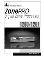
User Manual
1 2 6 0 / 1 2 6 1

WARNING FOR YOUR PROTECTION
READ THESE INSTRUCTIONS:
KEEP THESE INSTRUCTIONS
HEED ALL WARNINGS
FOLLOW ALL INSTRUCTIONS
DO NOT USE THIS APPARATUS NEAR WATER
CLEAN ONLY WITH A DRY CLOTH.
DO NOT BLOCK ANY OF THE VENTILATION OPENINGS. INSTALL IN ACCORDANCE WITH
THE MANUFACTURER’S INSTRUCTIONS.
DO NOT INSTALL NEAR ANY HEAT SOURCES SUCH AS RADIATORS, HEAT REGISTERS,
STOVES, OR OTHER APPARATUS (INCLUDING AMPLIFIERS) THAT PRODUCE HEAT.
ONLY USE ATTACHMENTS/ACCESSORIES SPECIFIED BY THE MANUFACTURER.
UNPLUG THIS APPARATUS DURING LIGHTNING STORMS OR WHEN UNUSED FOR LONG
PERIODS OF TIME.
Do not defeat the safety purpose of the polarized or grounding-type plug. A polar-
ized plug has two blades with one wider than the other. A grounding type plug has
two blades and a third grounding prong. The wide blade or third prong are pro-
vided for your safety. If the provided plug does not fit your outlet, consult an elec-
trician for replacement of the obsolete outlet.
Protect the power cord from being walked on or pinched particularly at plugs, con-
venience receptacles, and the point where they exit from the apparatus.
Use only with the cart stand, tripod bracket, or table specified by the manufacture,
or sold with the apparatus. When a cart is used, use caution when moving the
cart/apparatus combination to avoid injury from tip-over.
Refer all servicing to to qualified service personnel. Servicing is required when
the apparatus has been damaged in any way, such as power-supply cord or plug is
damaged, liquid has been spilled or objects have fallen into the apparatus, the appa-
ratus has been exposed to rain or moisture, does not operate normally, or has been
dropped.
POWER ON/OFF SWITCH: For products provided with a power switch, the power
switch DOES NOT break the connection from the mains.
MAINS DISCONNECT: The plug shall remain readily operable. For rack-mount or
installation where plug is not accessible, an all-pole mains switch with a contact
separation of at least 3 mm in each pole shall be incorporated into the electrical
installation of the rack or building.
FOR UNITS EQUIPPED WITH EXTERNALLY ACCESSIBLE FUSE RECEPTACLE: Replace fuse
with same type and rating only.
MULTIPLE-INPUT VOLTAGE: This equipment may require the use of a different line
cord, attachment plug, or both, depending on the available power source at instal-
lation. Connect this equipment only to the power source indicated on the equipment
rear panel. To reduce the risk of fire or electric shock, refer servicing to qualified
service personnel or equivalent.
This Equipment is intended for rack mount use only.
SAFETY INSTRUCTIONS
NOTICE FOR CUSTOMERS IF YOUR UNIT IS EQUIPPED
WITH A POWER CORD.
WA R N I N G : T H I S A P P L I A N C E M U S T B E E A R T H E D .
CONNECT ONLY TO A MAINS SOCKET OUTLET WITH
PROTECTIVE EARTHING CONNECTION.
The cores in the mains lead are coloured in accordance with
the following code:
GREEN and Y E L L OW - Earth BLUE - Neutral BROWN - Live
As colours of the cores in the mains lead of this appliance may
not correspond with the coloured markings identifying the ter-
minals in your plug, proceed as follows:
• The core which is coloured green and yellow must be con-
nected to the terminal in the plug marked with the letter E, o r
with the earth symbol, or coloured gre e n , or green and ye l l o w.
• The core which is coloured blue must be connected to the
terminal marked N or coloured black.
• The core which is coloured brown must be connected to the
terminal marked L or coloured red.
This equipment may require the use of a different line cord,
attachment plug, or both, depending on the available power
source at installation. If the attachment plug needs to be
changed, refer servicing to qualified service personnel who
should refer to the table below. The green/yellow wire shall be
connected directly to the units chassis.
WARNING: If the ground is defeated, certain fault conditions in
the unit or in the system to which it is connected can result in
full line voltage between chassis and earth ground. Severe injury
or death can then result if the chassis and earth ground are
touched simultaneously.
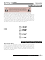
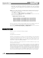
The symbols shown above are internationally accepted
symbols that warn of potential hazards with electrical
products. The lightning flash with arrowpoint in an equi-
lateral triangle means that there are dangerous voltages
present within the unit. The exclamation point in an equi-
lateral triangle indicates that it is necessary for the user to
refer to the owner’s manual.
These symbols warn that there are no user serviceable
parts inside the unit. Do not open the unit. Do not
attempt to service the unit yourself. Refer all servicing to
qualified personnel. Opening the chassis for any reason
will void the manufacturer’s warranty. Do not get the unit
wet. If liquid is spilled on the unit, shut it off immediately
and take it to a dealer for service. Disconnect the unit
during storms to prevent damage.
IMPORTANT SAFETY INSTRUCTIONS

U.K. MAINS PLUG WARNING
A molded mains plug that has been cut off from the cord is unsafe.
Discard the mains plug at a suitable disposal facility. NEVER UNDER
ANY CIRCUMSTANCES SHOULD YOU INSERT A DAMAGED OR CUT
MAINS PLUG INTO A 13 AMP POWER SOCKET. Do not use the
mains plug without the fuse cover in place. Replacement fuse covers
can be obtained from your local retailer. Replacement fuses are 13
amps and MUST be ASTA approved
to BS1362.
IMPORTANT SAFETY INSTRUCTIONS
ELECTROMAGNETIC
COMPATIBILITY
This unit conforms to the Pro d u c t
Specifications noted on the Declaration
of Conformity. Operation is subject to
the following two conditions:
• this device may not cause harmful
interference, and
• this device must accept any interfer-
ence received, including interference
that may cause undesired operation.
Operation of this unit within significant
electromagnetic fields should be avoided.
• use only shielded interc o n n e c t i n g
cables.
DECLARATION OF
CONFORMITY
Manufacturer’s Name: dbx Professional Products
Manufacturer’s Address: 8760 S. Sandy Parkway
Sandy, Utah 84070, USA
declares that the product:
Product name: dbx 1260 and dbx 1261
Note: Product name may be suffixed by the letters-EU.
Product option: None
conforms to the following Product Specifications:
Safety: IEC 60065 (1998)
EMC: EN 55013 (1990)
EN 55020 (1991)
Supplementary Information:
The product herewith complies with the requirements of the
Low Voltage Directive 73/23/EEC and the EMC Directive
89/336/EEC as amended by Directive 93/68/EEC.
Vice-President of Engineering – Pro
8760 S. Sandy Parkway
Sandy, Utah 84070, USA
Date:August 23, 2004
European Contact: Your local dbx Sales and Service Office or
Harman Music Group
8760 South Sandy Parkway
Sandy, Utah 84070, USA
Ph: (801) 566-8800
Fax: (801) 568-7583

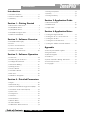
Introduction
0.1 ZonePro Features .............................................ii
0.2 Service Contact Info ........................................iii
0.3 Warranty...........................................................iv
Section 1 - Getting Started
1.1 Rear Panel Connections ...................................2
1.2 (1260)Front Panel.............................................3
1.3 (1261)Front Panel.............................................3
1.4 ZonePRO Designer GUI ..................................4
1.5 Software Installation.........................................4
Section 2 - Software Overview
2.1 ZonePRO Philosophy.......................................6
2.2 Views.................................................................6
2.3 Venue View Functions .....................................6
2.4 Unit View Functions.........................................8
2.5 Module View Functions .................................10
Section 3 - Software Operation
3.1 Overview.........................................................12
3.2 Connecting to the Device ..............................12
3.3 Configuration Wizard .....................................12
3.4 Parameter Editing ...........................................16
3.5 Storing Scenes.................................................17
3.6 Scene Wizard ..................................................17
3.7 Schedule Wizard.............................................18
3.8 File Save..........................................................18
3.9 Hardware Navigation .....................................18
Section 4 - Detailed Parameters
4.1 Input................................................................20
4.2 Parametric EQ.................................................20
4.3 Advanced Feedback Suppression (AFS) .......21
4.4 Automatic Gain Control (AGC) .....................23
4.5 Noise Gate ......................................................24
4.6 Compressor .....................................................25
4.7 De-Esser ..........................................................27
4.8 Notch Filters....................................................28
4.9 Router/Mixer...................................................28
4.10 Auto Warmth.................................................30
4.11 Band Pass Filter/Crossover .........................31
4.12 Output Dynamics .........................................32
4.13 Delay .............................................................33
4.14 Output Polarity .............................................33
Section 5- Application Guide
5.1 Restaurant Install ............................................36
5.2 Health Club.....................................................38
5.3 Night Club.......................................................40
Section 6- Application Notes
6.1 Using the Input Link Bus...............................44
6.2 Using the ZC as a Scene Selector .................44
6.3 Using the ZC-Fire ...........................................44
6.4 Using the Locate Function.............................45
6.5 Using the Address Network Wizard..............45
Appendix
A.1 Factory Reset/Flash Update...........................50
A.2 Specifications..................................................51
A.3 Block Diagram ...............................................52
A.4 Link I/O..........................................................53
A.5 Zone Controller Wiring and Install...............54
A.6 Network Overview ........................................57
A.7 Copyright........................................................64
ZonePRO™ User Manual
Table of Contents
Introduction
ZonePRO
™

INTRO
CUSTOMER SERVICE INFO
Defining the
ZonePRO
WARRANTY INFO
INTRODUCTION
ZonePRO
™

Introduction
ZonePRO™ User Manual
ii
ZonePRO
™
Congratulations on your purchase of the dbx
®
ZonePRO 1260 and/or 1261! The ZonePRO prod-
ucts are based on the same unparalleled design philosophy that made the DriveRack family
famous. This philosophy, “To provide everything you need between the sources and the ampli-
fiers,” creates a full featured processor capable of almost any BGM or commercial audio appli-
cation.
This manual will be your guide to understanding the full functionality of the powerful ZonePRO
units By combining the different components, the configuration possibilities are limitless. After
you have become familiar with the unit, we encourage you to experiment and find the most
effective and efficient way to run your system by utilizing the powerful processing of the
ZonePRO 1260 and 1261.
ZonePRO 1260/1261 features:
• Individual Zone Routing or Mixing
• Advanced Feedback Suppression (AFS
™
)
• AutoWarmth
®
• Auto Gain Control
• Compression
• Limiting
• Noise Gating
• Notch Filtering
• Bandpass and Crossover Filters
• Parametric EQ
• Security Lockout
• Wall Panel Control
• RS-232 and Ethernet Control
• IEC, UL, and CSA Certified
0.1 - ZonePro Features
INTRODUCTION

Introduction
ZonePRO
™
ZonePRO™ User Manual
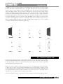
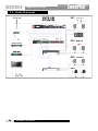
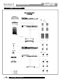
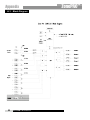
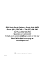
In addition to the processing available, the ZonePRO units provide intuitive wall-panel control
from the dbx Zone Controller (ZC) series. The ZC-1 and ZC-6 offer remote programmable
Volume control to any installation using the ZonePRO units. The ZC-2 provides programmable
Volume and Mute control. The ZC-3 and ZC-4 allow Source selection, Scene selection or Page
steering. ZC-FIRE provides an interface for fire safety systems. The ZC-7 remote offers page
steering from a programmable push button interface. The ZC-8 provides a single panel with
both push button volume control and source selection. The ZC-9 provides source selection. Up
to 12 Zone Controllers can be used with a single ZonePRO, and can either be wired in series
or parallel. The ZC-BOB was created to accommodate “home-run” or parallel wiring to the unit.
With a maximum length of 1,000 ft., the Zone Controllers offer a simple way to create a simple
yet elegant solution to many installation applications.
If you require technical support, contact dbx Customer Service. Be prepared to accurately
describe the problem. Know the serial number of your unit - this is printed on a sticker attached
to the top panel. If you have not already taken the time to fill out your warranty registration
card and send it in, please do so now.
Before you return a product to the factory for service, we recommend you refer to the manu-
al. Make sure you have correctly followed installation steps and operation procedures. If you
are still unable to solve a problem, contact our Customer Service Department at (801) 568-7660
for consultation. If you need to return a product to the factory for service, you MUST contact
Customer Service to obtain a Return Authorization Number.
No returned products will be accepted at the factory without a Return Authorization Number.
0.2 - Service Contact Info
iii
ZC-BOB ZC-1
ZC-2 ZC-3
ZC-4
ZC-Fire ZC-7
ZC-6 ZC-8
ZC-9

Introduction
ZonePRO™ User Manual
iv
ZonePRO
™
Please refer to the Warranty information on the following page, which extends to the first end-
user. After expiration of the warranty, a reasonable charge will be made for parts, labor, and
packing if you choose to use the factory service facility. In all cases, you are responsible for
transportation charges to the factory. dbx will pay return shipping if the unit is still under war-
ranty.
Use the original packing material if it is available. Mark the package with the name of the ship-
per and with these words in red: DELICATE INSTRUMENT, FRAGILE! Insure the package prop-
erly. Ship prepaid, not collect. Do not ship parcel post.
This warranty is valid only for the original purchaser and only in the United States.
1. The warranty registration card that accompanies this product must be mailed within 30 days
after purchase date to validate this warranty. Proof-of-purchase is considered to be the bur-
den of the consumer.
2. dbx warrants this product, when bought and used solely within the U.S., to be free from
defects in materials and workmanship under normal use and service.
3. dbx liability under this warranty is limited to repairing or, at our discretion, replacing defec-
tive materials that show evidence of defect, provided the product is returned to dbx WITH
RETURN AUTHORIZATION from the factory, where all parts and labor will be covered up to
a period of two years. A Return Authorization number must be obtained from dbx by tele-
phone. The company shall not be liable for any consequential damage as a result of the prod-
uct's use in any circuit or assembly.
4. dbx reserves the right to make changes in design or make additions to or improvements upon
this product without incurring any obligation to install the same additions or improvements
on products previously manufactured.
5. The foregoing is in lieu of all other warranties, expressed or implied, and dbx neither
assumes nor authorizes any person to assume on its behalf any obligation or liability in con-
nection with the sale of this product. In no event shall dbx or its dealers be liable for special
or consequential damages or from any delay in the performance of this warranty due to caus-
es beyond their control.
0.3 - Warranty

Getting Started
Section 1
ZonePRO
™

Getting Started
ZonePRO™ User Manual
2
Section 1
ZonePRO
™
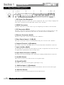
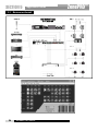
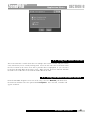
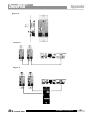
1. IEC Power Cord Receptacle
The ZonePRO 1260/1261 comes with a power supply that will accept voltages ranging from
100V-240V at frequencies from 50Hz-60Hz. An IEC cord is included.
2. S/PDIF Connection
This RCA connection is used to connect up to two digital input channels in the 1260/1261.
3. PC Connection (DB-9)
This DB-9 connection is used to communicate to the PC GUI and uses RS-232 protocol. This
connection requires a Null modem cable and one is included with the ZonePRO unit.
4. Ethernet Connection (RJ-45)
This RJ-45 connection is used to control the unit via Ethernet.
5. Zone Control Inputs 1-12 (RJ-45)
This input connection is used to send information and power to the ZC wall controllers.
6. Outputs Channels 1-6 (Euroblock)
The output section of the ZonePRO offers six electronically balanced Euroblock connectors.
7. Input Link Buss (RJ-45)
The ZonePRO offers an input buss that duplicates the first six inputs from one unit to the next
for applications requiring more than six output zones.
8. Input Source Channels 1-8 (RCA)
The input section of the ZonePRO offers eight mono-summing unbalanced RCA connectors.
9. Line/Mic Selector
This switch is used to select either the line or microphone input.
10. Signal/Clip LED
This LED is used to indicate microphone signal input or clip.
11. Mic/Line Inputs 1-2 (Euroblock)
The input section of the ZonePRO provides two Euroblock connectors for mic/line inputs.
12. Mic Gain Control
This knob is used to set the input gain for the microphone input.
1.1 - Rear Panel (1260 and 1261)

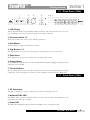
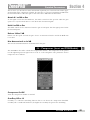
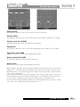
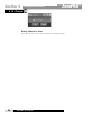
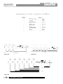
1. LCD Display
The backlit LCD display of the ZonePRO 1260 provides the end-user with all the necessary con-
trols including source selection, page steering, zone volume and mute.
2. Parameter Select 1-3
These three buttons are used to select and edit parameters.
3. Data Wheel
The Data Wheel is used to edit parameter values.
4. Page Buttons 1-2
The Page buttons are used to select the page mic path and steer it to selected zones.
5. Zone Select
These buttons are used to select output zones for front panel control.
6. Output Meters
The ZonePRO 1260 provides the user with six independent six-segment Lightpipe output meters that
range from -30 to +20 dBu.
7.Threshold Meters
The threshold meters indicate that the threshold level has been exceeded within the output
Compressor, Auto Gain Control, or Limiter sections, and gain reduction may be taking place.
1. PC Connection
This DB-9 connection is used to communicate to the PC via RS-232 protocol.
2. Network Traffic LED
This LED is used to indicate Network Traffic; it is also used to indicate and identify the unit
when the Locate function is enabled.
3. Power LED
This LED (when lighted), indicates that the ZonePRO 1261 is currently powered.
1.3 - Front Panel (1261)
1.2 - Front Panel (1260)
Getting Started
Section 1
ZonePRO
™
ZonePRO™ User Manual
3

Getting Started
ZonePRO
™
User Manual
4
Section 1
ZonePRO
™
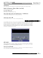
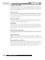
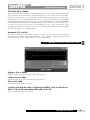
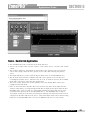
The ZonePro Designer Graphic User Interface (GUI) provides all the control functions neces-
sary to configure and program the ZonePro products. The GUI provides network tools for
configuring your control network as well as multiple “Wizard” functions for configuring the
system routing, implementing end-user control surfaces, programming parameters, and even
creating automatic system changes. Understanding the ZonePro Designer software is the key
to getting full functionality from ZonePro products.
Minimum System Requirements for ZonePRO Designer are:
1 GHz or faster processor
Windows 2000 or XP
256 MB RAM or (512 MB Recommended)
Recommended screen resolution: 1024 x 768 pixels or higher
Installation
• Install the ZonePRO GUI software from either the dbx website at www.dbxpro.com or from
the included CD ROM onto your computer.
• Once the software setup is downloaded, double click on the file named: ZonePRO setup.
• The application will proceed to prompt you for the installation location.
• Once the software installation has been completed, it is recommended that you restart your
computer.
Note
You must disable virus protection software during the installation of
ZonePRO Designer.
1.5 - Software Installation
1. 4 - ZonePRO Designer GUI

SOFTWARE
OVERVIEW
Section 2
ZonePRO
™

Software Overview
6
Section 2
ZonePRO
™
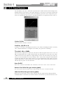
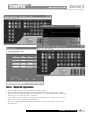
For your convenience, all the configuration and editing features of the ZonePRO™ 1260 and
1261 are performed via the included ZonePRO Designer GUI. This section has been created to
act as a tutorial for performing various editing aspects of the unit.
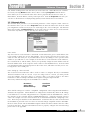
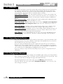
The philosophy of the ZonePRO Designer and the files that it creates, are built around the con-
cept of a configuration, a scene and a device file; all of which are found in the Unit View
(Please see below).
Configuration
The configuration includes all of the processing blocks, the I/O configuration, and the zone
controllers. The configuration is set up by going through the Configuration Wizard. The
ZonePRO device can only have one configuration, so all configuration editing must be com-
pleted before you can store any scenes. For more information on the configuration see
Configuration Wizard in section 3.3.
Scenes
A scene consists of the parameters for all the modules and the assignment of zone controllers
to a zone. The ZonePRO products allow switching of scenes from the Real Time Clock, or from
a ZC zone controller. Up to 50 scenes can be stored in the ZonePRO unit. Scenes can be stored
by clicking on the Store Scene button in the Unit view. For more information on scenes, see
section 3.5.
Device
The configuration, scenes, and schedule information can all be stored off to a device file or .zpd
(ZonePRO device). Storing a device file to the computer and then recalling it into another
ZonePRO unit allows for exact duplication of a system in a single file download. The device
file can be stored by selecting File Save in the Unit view.
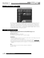
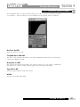
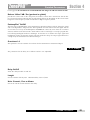
There are three different views within the ZonePRO Designer GUI; Venue view, Program
screen, and Module view. Venue view Venue View gives you a global view of the network
including all your units if you are using Ethernet control. Double clicking on a unit icon in the
Venue view take you to the Unit view. Unit View (sometimes called program screen) pro-
vides you with a graphic representation of the configuration of the individual ZonePRO unit,
including all the processing modules and their positions in the signal path. The program screen
also offers access to meters, scene storing and loading, the Wizard functions, and file storing.
Double clicking on the processing modules take you to the Module view. Module view (also
called edit screen) provides access to the processing parameters. Editing of parameters is done
in Module view.
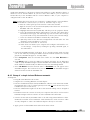
2.3.1 Device Menu
The ZonePRO Designer GUI provides a mechanism for creating scenes and device files while
not physically connected to a ZonePRO unit. To work off-line, open the GUI, select the
Device Menu from the menu bar then select Add. At this point you will be prompted to
choose a 640, 641, 1260 or 1261. Once the unit has been inserted into GUI you can proceed
to configure, edit, create scenes, and save ZonePRO device files. If you highlight the
ZonePRO unit and select Edit, you will be taken to the Unit view so that you can edit the
2. 3 - Venue View Functions
2. 2 - Views
2. 1 - ZonePRO Philosophy
ZonePRO
™
User Manual

unit; double clicking on the unit also takes you to the Unit view. When off - l i n e , You can delete
the unit by selecting D e l e t e f rom the Device Menu. Selecting P r o p e rt i e s f rom the Device
menu allows you to view and edit some of the device properties like the device's name, its
MAC address, Its Node address, and its peak output level. From the P r o p e r t i e s selection, you
can also see the firm w a re or OS (Operating System) version that the device has loaded
2.3.2 Network Menu
The Network Menu provides access to network parameters. If the computer cannot connect to
the ZonePro device you can select Properties from the Network Menu and check the COM
port assignment to make sure that you are connecting to the correct COM port. The Network
Menu also provides an Address Tool that can be used to discover other devices on the network
and resolve any address conflicts that may arise between units.
Note: Nodes
Any device that is on the network is considered a node and must be given a node address; this
is just usually a simple one or two digit number. Once you place the first device on the net-
work the GUI will assist you as you add further devices by adding 1 to the previous node
address as you add devices. For example, if the first device on the network is node address 1,
the second will be 2, and the third 3, unless you specifically change the node address with the
Network Address Tool. If the computer cannot connect to the ZonePRO device, check the COM
port assignment under Network Properties in the Venue View, and make sure that you are con-
necting to the correct COM port.
Note: Setting up a basic Network
The enclosed crossover Ethernet cable is used to connect a computer directly to a ZonePRO
1260/1261 without a hub or a switch. If you are using a hub or a switch, you must provide
your own cabling. Since this cable is a crossover cable, it can not be used to wire Zone
Controllers or link to multiple ZonePRO units together using the Input Link Bus.
The factory default IP settings for the ZonePRO are as follows:
IP Address: 169.254.2.2
Subnet Mask: 255.255.0.0
Default Gateway: 0.0.0.0
These default settings are used for a simplified configuration when using Microsoft Window's
Automatic IP assignment. When Windows is configured to automatically obtain its IP settings
it will fall back to a network configuration that is compatible with the ZonePRO 1260 / 1261 if
the computer is on a network without a DHCP/BOOTP server. Using the enclosed crossover
cable is an example of such a network and is the recommended method of configuring a new
unit. Please keep in mind that it takes MS Windows 1-2 minutes after the cable is attached and
the ZonePRO is powered on for it to have its network settings compatible with the ZonePRO.
Because of this, do not start the ZonePRO Designer software for about 2 minutes after the cables
have been attached. For more information on how to properly configure the network setting
please refer to the appendix.
Software Overview
Section 2
ZonePRO
™
7
ZonePRO
™
User Manual

Software Overview
8
Section 2
ZonePRO
™
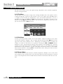
The Unit View provides access to the signal routing configuration, Zone Controller assignment,
and processing parameters.
2.4.1 File Menu
The File Menu selection allows saving of the existing ZonePRO device file (.zpd) as well as
recalling of other files. The device file provides a way to store off the entire ZonePRO unit to
a computer, which includes the configuration, scenes, and schedule information. To save a
ZonePRO device file, select File then Save from the Menu bar. Recalling a saved file can be
done by selecting Open from the File Menu. Once all of your changes have been made, sim-
ply close the file with the Close selection.
2.4.2 Edit Menu
To edit a processing module, double click on that module. Adjust the module to taste; make
sure that the module is engaged. This is usually indicated by the module ON button in the
upper left corner of the parameter section. Although process editing is done in real-time, the
changes can either be discarded or accepted by selecting the OK or CANCEL button.
Parameters can be copied and pasted between like modules in the ZonePRO GUI. From the
program screen either right click on the module and select Copy, or select Edit and Copy from
the Menu Bar to Copy parameters. To paste, either right click and select Paste, or click on Edit
Paste from the Menu bar. Selecting Time in the Edit Menu allows editing of the date and time
in the ZonePRO device's real time clock
2.4.3 Scenes Menu
Scenes include parameter data and zone controller assignment. Multiple scenes can be saved
and recalled by either clicking on the Scene tab of the Menu bar and selecting Store or Recall
Scene, or by using the Store Scene and Recall Scene buttons at the bottom of the Unit view win-
dow.
2. 4 - Unit View Functions
ZonePRO
™
User Manual

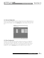
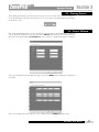
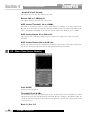
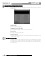
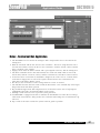
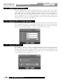
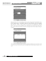
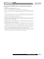
2.4.4 Wizard Menu
The Wizard Menu provides setup functions for the unit configuration, scene changes that might
involve routing or ZC assignment changes, and automated scene changes via the real time clock
schedule. Configuration of the ZonePRO device is done from the Configuration Wizard and
allows setup of the inputs and outputs along with selection of their processing modules, zone
controller setup, signal routing, and front panel setup. For a detailed operation description see
"The Wizard" section 3.3. The image on the following page shows the first page of the
Configuration Wizard page.
The Scene Wizard allows routing and ZC assignment changes for different scenes. Scheduling
Scene Changes is done using the Schedule Wizard. Selecting the Schedule Wizard from the
Wizard Menu reveals the image below where scenes can be recalled at various times through-
out the day or week.
2.4.5 Help Menu
The Help Menu provides for some special functions like retrieving Hardware Info such as
Checksum and Fire Safety status. There is a Locate function similar to the Locate function
found under the Device Menu in the Venue view. A special provision for the 641 and 1261 is
found in the Help menu under 641/1261 Operations that can be used to do hard or soft resets
on those units if the need arises. Finally the GUI software version is found under About in the
Help menu.
2.4.6 Meters Button
The Meters Button, found at the bottom of the Unit view can be used to turn the meters off.
Turning the meters off will help speed the communication and processing of slower computer
systems. The ZonePRO Designer GUI defaults with the meters turned on.
Software Overview
Section 2
ZonePRO
™
9
ZonePRO
™
User Manual

Software Overview
10
Section 2
ZonePRO
™
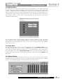
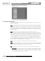
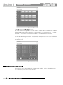
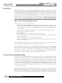
Double clicking on a processing module provides access to those parameters.
All modules except for the input Gain module and the output Polarity have ON/OFF buttons
allowing the processing of that module to be bypassed. Any changes made to the processing
happen in real time as long as the ON/OFF button is turned on (indicated by the button turn-
ing red). These changes can be accepted or discarded upon exiting the module by selecting
either the OK or CANCEL button at the bottom of the module view.
2. 5 - Module View Functions
ZonePRO
™
User Manual

S O F T WA R E
OPERATION
Setup
Section 3
ZonePRO
™

Software Operation
12
Section 3
ZonePRO
™
ZonePRO
™
User Manual
The Software operation section of the manual will provide in-depth step by step instructions
for setting up a ZonePro 1260 or 1261 and any Zone Controllers that may be used with it.
The following subsections will provide you with detailed information regarding the various
set up functions. Typical procedure of a ZonePro 1260 is as follows:
Step 1, Connect to the Device - Use either RS-232 or Ethernet to connect to the ZonePro unit.
Step 2, Configuration Wizard - Once you have connected to the device you can begin to con-
figure the signal routing, DSP functions, and wall panel controllers using the Configuration
Wizard.
Step 3, Parameter Editing - Double clicking on the various modules allows editing of parame-
ters to adjust settings for individual installations or scenes.
Step 4, Scene Storing - Whether using a single scene or many, storing the scene is important to
make sure that all parameter changes are saved. If just one scene is desired you can save it
as the Default scene.
Step 5, Scene Wizard - If multiple scenes are desired with routing or zone controller assign-
ment changes, use the Scene Wizard to make those changes. Repeat Steps 3 and 4.
Step 6, Schedule Wizard - If multiple scenes are to be loaded using the Schedule function, set
up the Schedule using the Schedule Wizard for each scene change. Make sure the clock is
correct by clicking on Edit then Time from the Menu Bar.
Step 7, File Save - It is recommended that you save off a copy of your ZonePRO device file
using the File Save on the Menu bar. This file is a back-up and might come in handy for
future installations.
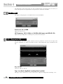
If you are connecting to a device with an RS-232 connection the connection should be estab-
lished fairly quickly. If you have difficulty connecting to the ZonePRO unit you can use the
Network Wizard to select the proper COM port.
If you are using your Ethernet port on your computer this may take up to two minutes as
Windows tries to first establish an Ethernet connection. If after two minutes your computer
cannot connect to the ZonePro device you may want to select NETWORK/GO OFFLINE wait
ten seconds then select NETWORK/GO ONLINE from the Venue view.
If you are setting up a larger network with multiple devices, please see Appendix for more
information.
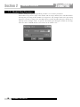
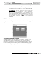
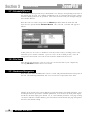
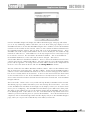
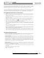
The Wizard function is used to configure the ZonePRO signal routing, processing modules,
Zone Controllers and Front Panel. It provides a menu based decision tree to speed setup. This
sub-section will walk you through each page of the Wizard function.
From the Program Screen view of the setup, select the Wizard pull down from the
menu bar and then select the option labeled Configuration Wizard. Once selected, a win-
dow will appear as follows:
3.3 - Configuration Wizard
3.2 - Connecting to the Device
3.1 - Overview
Page is loading ...
Page is loading ...
Page is loading ...
Page is loading ...
Page is loading ...
Page is loading ...
Page is loading ...
Page is loading ...
Page is loading ...
Page is loading ...
Page is loading ...
Page is loading ...
Page is loading ...
Page is loading ...
Page is loading ...
Page is loading ...
Page is loading ...
Page is loading ...
Page is loading ...
Page is loading ...
Page is loading ...
Page is loading ...
Page is loading ...
Page is loading ...
Page is loading ...
Page is loading ...
Page is loading ...
Page is loading ...
Page is loading ...
Page is loading ...
Page is loading ...
Page is loading ...
Page is loading ...
Page is loading ...
Page is loading ...
Page is loading ...
Page is loading ...
Page is loading ...
Page is loading ...
Page is loading ...
Page is loading ...
Page is loading ...
Page is loading ...
Page is loading ...
Page is loading ...
Page is loading ...
Page is loading ...
Page is loading ...
Page is loading ...
Page is loading ...
Page is loading ...
Page is loading ...
Page is loading ...
Page is loading ...
Page is loading ...
-
 1
1
-
 2
2
-
 3
3
-
 4
4
-
 5
5
-
 6
6
-
 7
7
-
 8
8
-
 9
9
-
 10
10
-
 11
11
-
 12
12
-
 13
13
-
 14
14
-
 15
15
-
 16
16
-
 17
17
-
 18
18
-
 19
19
-
 20
20
-
 21
21
-
 22
22
-
 23
23
-
 24
24
-
 25
25
-
 26
26
-
 27
27
-
 28
28
-
 29
29
-
 30
30
-
 31
31
-
 32
32
-
 33
33
-
 34
34
-
 35
35
-
 36
36
-
 37
37
-
 38
38
-
 39
39
-
 40
40
-
 41
41
-
 42
42
-
 43
43
-
 44
44
-
 45
45
-
 46
46
-
 47
47
-
 48
48
-
 49
49
-
 50
50
-
 51
51
-
 52
52
-
 53
53
-
 54
54
-
 55
55
-
 56
56
-
 57
57
-
 58
58
-
 59
59
-
 60
60
-
 61
61
-
 62
62
-
 63
63
-
 64
64
-
 65
65
-
 66
66
-
 67
67
-
 68
68
-
 69
69
-
 70
70
-
 71
71
-
 72
72
-
 73
73
-
 74
74
-
 75
75


Automotive Data Solutions ZonePro 1261 User manual
- Category
- Supplementary music equipment
- Type
- User manual
- This manual is also suitable for
Ask a question and I''ll find the answer in the document
Finding information in a document is now easier with AI
Other documents
-
Vonino Xavy L8 Hard reset manual
-
 VXDAS VXDAS NT510 OBD2 Scanner Enhanced OBDII Code Reader Installation guide
-
dbx ZonePro 1261m Quick start guide
-
-
 dbx Pro AFS 224 User manual
-
dbx Pro 266XL COMPRESSOR / GATE User manual
-
Rane DA 26 User manual
-
-
-

