Page is loading ...

IMPORTANT:
Go to www.extron.com for the complete
user guide, installation instructions, and
specifications before connecting the
product to the power source.
MTP DA4 and DA8 • Setup Guide
This guide provides basic instructions for an experienced installer to set up and
J9
Disable
Mute
(Default)
or
Enable
Mute
J3
Serial
or
Audio
(Default)
operate an Extron MTP DA4 or DA8 distribution amplier.
Pre-installation — Jumpers
See the gure at the right or see “Termination and Mute Jumpering” in the
MTP DA4 and MTP DA8 User Guide for more information.
NOTE: The jumpers have no effect when the DA is part of an MTP CV/SV
series, or VTT001/VTR001 system.
Jumper J3
This sets the DA to properly terminate RGB video as well as the audio (default) or serial portion of the input signal.
Jumper J9
This sets the DA to always pass the audio or serial link regardless of the contact closure mute status (default). It can also be set
to mute the audio or serial link when its video mute function is activated.
Installation
Step 1 — Mounting
Turn off or disconnect all equipment power sources and mount the MTP DA as required. A mounting example is shown below).
See “Mounting” in the user guide for more mounting options.
Use 2 mounting holes on
opposite corners.
1/2 Rack Width False Front
Face Plate
(2) 4-40 x 3/16" screws
6" Deep Rack Shelf
MTP DA SERIES
Figure 1. Mounting the MTP DA
Step 2 — Input from the Transmitter
Terminate a TP cable as shown in gure 3. Connect the cable into a MTP transmitter
1234
A/V INPUT
A/V OUTPUTS
5
Pin
1
2
3
6
7
8
4
Wire color
White-green
Green
White-orange
White-blue
Orange
White-brown
Brown
Wire color
T568A T568B
White-orange
Orange
White-green
White-blue
Green
White-brown
Brown
Blue Blue
12345678
RJ-45
Connector
Insert Twisted
Pair Wires
Pins:
and into the AV input connector.
Step 3 — Outputs to the Receivers
Terminate up to four or eight (depending on model) TP cables as shown in the gure to the
right. Connect the cables into the DA AV output ports and into receivers that are compatible
with the transmitter.
NOTES:
• The inputs and outputs should be terminated using the same standard on both
ends of the cable.
• Only use the TIA/EIA T568A standard when using Enhanced Skew-Free™ AV
cable.

68-975-50 Rev. D
01 13
Extron Headquarters
+800.633.9876 Inside USA/Canada Only
Extron USA - West Extron USA - East
+1.714.491.1500 +1.919.850.1000
+1.714.491.1517 FAX +1.919.850.1001 FAX
Extron Europe
+800.3987.6673
Inside Europe Only
+31.33.453.4040
+31.33.453.4050 FAX
Extron Asia
+800.7339.8766
Inside Asia Only
+65.6383.4400
+65.6383.4664 FAX
Extron Japan
+81.3.3511.7655
+81.3.3511.7656 FAX
Extron China
+4000.EXTRON
+4000.398766
Inside China Only
+86.21.3760.1568
+86.21.3760.1566
FAX
Extron Middle East
+971.4.299.1800
+971.4.299.1880 FAX
Extron Korea
+82.2.3444.1571
+82.2.3444.1575 FAX
Extron India
1800.3070.3777
Inside India Only
+91-80-3055.3777
+91 80 3055 3737
FAX
© 2013 Extron Electronics All rights reserved. www.extron.com
MTP DA4 and DA8 • Setup Guide
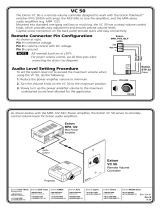
Step 4 — Power
Power Supply
Output Cord
SECTION A–A
Ridges
Smooth
AA
Wire the 2-pole captive screw connector for the external 12 VDC power supply
(see the image on the right).
Grounding the Power Input Port
Extron MTP DA products can be adversely affected by electrostatic discharge
(ESD) if they are not grounded correctly.
To prevent malfunctions or product damage, an experienced installer can correctly
ground an Extron MTP DA product by inserting one end of the grounding wire to
the negative or ground pin on the power input connector (see the image on the
right). Tie the other end of the wire to an earth ground.
Plug the connector into the MTP DA.
If you have any questions about how to ground a product in a specic application,
contact an Extron technical support specialist.
Operation — Mutes
To mute an output, tie the Output Mute pin to the ground ( ). To mute all outputs, tie the A pin to the ground (see gure 2 for more
information).
1234 5678A
MTP DA8
Output Mute Connector
1 234A
MTP DA4
Output Mute Connector
Pin Contact
Closure
Function
1 Out #1 Mute output #1
2 Out #2 Mute output #2
3 Out #3 Mute output #3
4 Out #4 Mute output #4
5 Out #5 Mute output #5
6 Out #6 Mute output #6
7 Out #7 Mute output #7
8 Out #8 Mute output #8
A Out All Mute all output
Gnd Ground
0.5A MAX
12V
POWER
+
-
OUTPUT MUTE
1
2
3
4
5
6
7
8
A
INPUT
1 2
3
4
5 6 7 8
OUTPUTS
OUTPUT
SHARP
L
R
INPUT VIDEO
12V
0.5a
MAX
MTP R SV A
OUTPUT
SHARP
L R
INPUT
VIDEO
12V
0.5a
MAX
MTP R SV A
OUTPUT
SHARP
L R
INPUT
VIDEO
12V
0.5a
MAX
MTP R SV A
OUTPUT
SHARP
L
R
INPUT
VIDEO
12V
0.5a
MAX
MTP R SV A
INPUT
MTP T SV A RCA
VIDEO
OUTPUT
L R
12V
0.5a
MAX
Flat Panel
Display
Extron
MTP DA8
Twisted Pair
Distribution Amplier
Up To
8 Receivers
Extron
MTP T AV RCA
Twisted Pair
Transmitter
DVD
Extron
MTP R AV
Twisted Pair
Receivers
TP Cable
TP Cable
Figure 2. Mute Connector and Pinout Figure 3. Example of a Typical MTP DA8 Application
POWER
12V
xA MAX
Tie
Wrap
Rear
Panel
Ridges
Earth
Ground
3/16"
(5 mm)
Max.
/