Page is loading ...

© Travis Industries 8/24/2020 - 1450 42 Apex CF
42 Apex Clean Face
Installation Manual
12521 Harbour Reach Drive
Mukilteo, WA 98275
This manual is available online in French.
Manuel est disponible en ligne en Francais.
www.travisproducts.com
Wood-Burning
Zero-Clearance
Fireplace
© 2018, Travis Industries
$10.00 100-01450
Report # 028WF102S
U.L. 127-2015 and ULC-S610-M87
(R1998)

2 Introduction
© Travis Industries 8/24/2020 - 1450 42 Apex CF
Overview
This manual details the installation requirements for the 42 Apex Clean Face (CF) wood-burning
fireplace. For operating and maintenance instructions, refer to the 42 Apex CF Owner's Manual.
Keep this manual for future use.
Listing Details
This appliance was listed by OMNI Test Labs to U.L. 127 and ULC-S610-M87 – report number
028WF102S. The listing label is attached to the base of the fireplace and can be viewed by accessing the
fan compartment.
IAS (ICBO) Approval
This appliance was listed by OMNI Test Labs – IAS (ICBO) # TL-130.
Emissions
This heater meets the 2020 U.S. EPA’s cord wood emission limits for wood heaters. Tested to EPA Alt-125,
ASTM E3053-17, ASTM 2515-11, CSA B415.1-10 this heater has been shown to deliver heat at rates
ranging from 13,537 to 49,626 BTU/hr and an emission value of .93 g/h. Report No. 0028WF102E
National Fireplace Institute

Table of Contents 3
© Travis Industries 8/24/2020 - 1450 42 Apex CF
Overview .......................................................................... 2
Listing Details ................................................................... 2
IAS (ICBO) Approval .................................................... 2
Emissions ......................................................................... 2
National Fireplace Institute ........................................... 2
Installation Warnings .................................................... 4
Operating Warnings ...................................................... 4
Installation Options ........................................................... 5
Heating Specifications ...................................................... 5
Dimensions ...................................................................... 5
ITEMS UNIQUE TO THIS FIREPLACE ........................... 6
Header Height is Determined by the Convection Air Outlet
..................................................................................... 6
The Chase (fireplace enclosure) Must Be Ventilated ... 6
Air-Cooled Chimneys Offsets Inside Chase Must Be
Directed to the Rear to Clear Manifold ......................... 6
Packing List ...................................................................... 7
Recommended Order of Installation ................................. 7
Installation Recommendations for Cold Environments ..... 8
Insulated Chimney is Strongly Recommended ............. 8
Use “P” Trap & Insulated Duct in the Cooling Duct. ...... 8
Use Bi-Metallic Damper with Air-Cooled Chimney ........ 8
Use Outside Air “P” Trap and Insulated Duct................ 8
Daily Requirements for Homeowners ........................... 8
OTHER ITEMS ......................................................... 8
Fireplace Placement Requirements ................................. 9
Clearances to Fireplace ................................................ 9
Fireplace Placement ..................................................... 10
Minimum Framing Dimension ........................................... 11
Framing Dimensions at 45° .............................................. 12
Convection Air Manifold ................................................... 13
Chase Ventilation (REQUIRED) ....................................... 14
Chase Ventilation Overview ......................................... 14
Chase Ventilation Grills ................................................ 15
Dimensions ............................................................... 15
Chase Ventilation – Front Configuration ....................... 16
Chase Ventilation – Side Configuration ........................ 17
Raised Fireplaces............................................................. 18
Approved Chimney ........................................................... 19
Air Cooled Chimney Requirements (8” Inner Dia., 12” Outer
Dia.) .................................................................................. 20
Part Numbers (available through Travis Industries) ...... 20
Anchor Plate Installation ............................................... 20
Cooling Duct Installation ............................................... 21
Air Cooled Chimney - Clearances to Combustibles ..... 22
Air Cooled Chimney – Use of Offsets in Chase ............ 23
Air Cooled Chimney – Installation and System Height . 24
Air Cool Chimney - Offset Requirements (30° Elbows) 25
Firestops ...................................................................... 25
Chimney Offset Chart ................................................... 25
Insulated Chimney Requirements (7” Inner Diameter) ..... 26
Security ASHT+ (S2100+) Part Numbers (available
through Travis Ind.) ...................................................... 26
Security ASHT+ - Clearances to Combustibles ........ 26
Security ASHT+– Anchor Plate Installation .............. 26
Security ASHT+– Offset Chart ................................. 26
Insulated Chimney – Alternative Manufacturers ........... 27
Anchor Plate Installation ........................................... 27
Insulated Chimney – Installation and System Height ... 28
Insulated Chimney - Offset Requirements (30° Elbows)
..................................................................................... 29
Firestops ...................................................................... 29
Chimney Termination Requirements ................................ 30
Convection Air Manifold and Non-Combustible Framing . 31
Contents of Framing Hardware Box ............................. 31
Contents Strapped to Exterior of Fireplace & Inside
Firebox ......................................................................... 32
Steps for Installing the Convection Air Manifold ........... 33
Upper Manifold and Trim Dimensions .......................... 35
Dimensions .............................................................. 35
Steps for Installing the Non-Combustible Framing ....... 36
Electrical Line Hookup ..................................................... 38
Wiring Diagram ............................................................ 38
Fireplace Junction Box ................................................. 39
Inside of Junction Box .................................................. 39
External Wiring Installation............................................... 40
External Wiring Installation (continued) ............................ 41
Back Side of the Combustor Temp Display .................. 41
Air Intake Installation ........................................................ 42
Air Intake Locations ...................................................... 43
Facing Requirements ....................................................... 44
Facing Requirements (continued) .................................... 45
Mantel Requirements ....................................................... 46
Hearth Requirements ....................................................... 47
Finalizing the Installation .................................................. 48
Index ............................................................................ 50

4 Safety Precautions
© Travis Industries 8/24/2020 - 1450 42 Apex CF
Installation Warnings
Read this entire manual before installing the fireplace.
Failure to install this fireplace in accordance with all local codes and the requirements listed in this
manual may result in property damage, bodily injury, or even death.
Notify your insurance company before installing this fireplace.
Contact your local building officials to obtain a permit and information on installation restrictions or
inspection requirements in your area.
Notify your insurance company of this fireplace.
The requirements listed below are divided into sections. All requirements must be met
simultaneously. The order of installation is not rigid – the qualified installer should follow the
procedure best suited for the installation.
Modifications of the fireplace (doors, air inlet systems, damper control, or any other component
supplied by Travis Industries) or use of any component part not approved by Travis Industries in
combination with this fireplace system will void the listing and warranty.
This fireplace is not approved for use in a mobile home.
Travis Industries, Inc. grants no warranty, implied or stated, for the installation or
maintenance of your heater, and assumes no responsibility of any consequential damage(s).
Operating Warnings
WARNING: FIREPLACE SHOULD BE OPERATED ONLY WITH DOORS FULLY OPEN OR DOORS
FULLY CLOSED. IF DOORS ARE LEFT PARTLY OPEN, GAS AND FLAME MAY BE DRAWN OUT
OF THE FIREPLACE OPENING, CREATING RISKS OF BOTH FIRE AND SMOKE.
Creosote – Formation and Need for Removal
When wood is burned slowly it produces tar and other organic vapors which combine with expelled
moisture to form creosote. The creosote vapors condense in the relatively cool chimney flue of a
slow-burning fire. As a result, creosote residue accumulates on the flue lining. When ignited this
creosote makes an extremely hot fire.
The chimney shall be inspected at least twice a year during the heating season to determine when a
creosote buildup has occurred.
When creosote has accumulated it shall be removed to reduce the risk of a chimney fire.
Never use gasoline, gasoline-type lantern fuel, kerosene, charcoal lighter fluid, or similar liquids to
start or ‘freshen up’ a fire in this fireplace. Keep all such liquids well away from the fireplace while it is
in use.
Disposal of Ashes
Ashes should be placed in a metal container with a tight-fitting lid. The closed container of ashes
should be placed on a noncombustible floor or on the ground, well away from all combustible
materials, pending final disposal. If the ashes are disposed of by burial in soil or otherwise locally
dispersed, they should be retained in the closed container until all cinders have thoroughly cooled.
A fireplace insert shall not be installed in a factory-built fireplace unless tested with the fireplace.
Proposition 65 Warning: Fuels used in gas, woodburning or oil fired appliances, and the products of combustion of such fuels,
contain chemicals known to the State of California to cause cancer, birth defects and other reproductive harm.
California Health & Safety Code Sec. 25249.6
Travis Wood Burning Fireplaces, Stoves and Inserts are protected by one or more of the following patents; U.S. 9,170,025,
4,665,889 as well as other U.S. and Foreign Patents pending.

Features and Specifications 5
© Travis Industries 8/24/2020 - 1450 42 Apex CF
Installation Options
Residential (not approved for HUD Mobile Homes)
Straight or Corner Placement
Raised or Floor Placement
Raised or Floor Hearth
Internal or External Chase
5 Air Intake Locations
1 Electrical Connection Location
Heating Specifications
Approximate Heating Capacity (in square feet)* .................. Up to 2,500 sq. ft.
Maximum Burning Time ....................................................... Up to 12 Hours
* Heating capacity will vary with floor plan, insulation, and outside temperature.
Dimensions
42"*
1067mm*
Optional Front Inlet
Knock-Outs
22-7/8"*
582mm*
Weight = 670 lbs. (304 Kg)
* Includes the 1/2" (13mm) stand-offs
3" (77mm) Air Intak
e
(may be re-routed t
o
left, back or bottom)
47-1/4"
1201mm
Electrical Input &
External Control
Junction Box
26"
661mm
1-1/8"
29mm
10-1/8"*
258mm*
Convection Air Outlet
(attach lower manifold to
this duct opening)
Side Inlets
38"
966mm
9-5/8"
245mm

6 Installation (for qualified installers only)
© Travis Industries 8/24/2020 - 1450 42 Apex CF
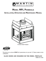
ITEMS UNIQUE TO THIS FIREPLACE
Header Height is Determined
by the Convection Air Outlet
The height of the convection air
outlet determines the framing
header height (see illustration to
the right and page 13 for details).
The desired outlet height should
be determined prior to framing.
Make sure all minimum
clearances are maintained.
The Chase (fireplace enclosure)
Must Be Ventilated
The chase (fireplace enclosure) must be
ventilated to provide proper fireplace
cooling (see illustration to the right and
page 14 for details). Grills are included
for this purpose.
If ventilated to the sides, a minimum 2” air
space is required(see illustration below
and page 17 for details). The framing
may need to be altered to provide proper
ventilation.
Air-Cooled Chimneys Offsets Inside Chase Must Be Directed to the Rear to Clear Manifold
When using offsets inside the chase the offsets will need to be angled back slightly to allow the chimney to clear
the upper manifold (see page 23). In most installations this offset will need to be angled back 1-1/2”.
42 Apex CF
Fireplace
Min. 3-1/2"
Lower Framing (included)
Upper Convection Manifold
6-1/2" *
Max. 116-1/2"
Min. 78-1/2" **
Lower Convection Manifold
5" Alum. Flex Duct (included
)
Framing Heade
r
Celing
Convection Air Outlet
Upper Framing (included)
MIn. 2"
Max.. 5-1/2"
This shaded area on both sides of the fireplace must be left
unobstructed when using the side chase ventilation configuration.
TOP OF FIREPLACE
b
c
a
a

Installation (for qualified installers only) 7
© Travis Industries 8/24/2020 - 1450 42 Apex CF
Packing List
NOTE: The log stop is secured for shipping with a set screw on the back of the log stop support. Loosen
the set screws with a 1/8” hex wrench and remove the log stop to access the internal
components.
Bricks (2 boxes – left side and right side)
Baffle
Air Intake Parts (10’ of 3” diameter duct,
intake hood, hood bezel, and 2 hose
clamps)
Ember strip
Switch Plate with Combustor Temp. Display
and Rheostat
Door Tool
Manifold / Non-Combustible Framing Parts
Face (ships pre-attached to the fireplace)
Owner’s manual
Pair of gloves
Upper Manifold Trim
Front Ventilation Grill
Small Ventilation Grills
5” Aluminum Flex Duct
Recommended Order of Installation
Frame the opening for the fireplace. Leave the non-combustible framing and facing above the
fireplace open to allow for chimney installation.
Secure the fireplace to the framing/floor.
Install the chimney (and cooling air, if applicable), electrical, external wiring (rheostat, catalytic temp
reader, etc.), and outside air.
Install the Convection Air Manifold and non-combustible framing – see “Convection Air Manifold
Installation”.
Install the ventilation grills used for chase ventilation
Install the hearth (if applicable)
Install the non-combustible facing.
Install the non-combustible mantel (if applicable).
Finalize the installation/

8 Installation (for qualified installers only)
© Travis Industries 8/24/2020 - 1450 42 Apex CF
Installation Recommendations for Cold Environments
If you live in the area depicted in black in the illustration to the
right (or in Canada), we recommend the following steps be
taken to minimize cold air infiltration.
Insulated Chimney is Strongly Recommended
Insulated chimney does not require cooling ducts and is
therefore preferred for cold environments. This is the
number one method for improving cold weather performance.
Use “P” Trap & Insulated Duct in the Cooling Duct.
If using air-cooled chimney, we recommend insulating the
intake duct and putting in a “P” trap to help prevent air
circulation when the fireplace is not in use. A typical “P” trap
design is shown in the illustration to the right.
Use Bi-Metallic Damper with Air-Cooled Chimney
If using air-cooled chimney, we recommend the use of the bi-
metallic damper. This component (part # 250-01741) is an 18”
section of Duravent pipe that is installed at the top of the
chimney, directly below the cap. It has a heat-activated damper
that helps reduce cold air from entering the cooling ducts while
the fireplace is not in operation.
Use Outside Air “P” Trap and Insulated Duct
We recommend putting in a “P” trap in the outside air duct (used to supply air to the firebox) to prevent air
circulation when the fireplace is not in use. A typical “P” trap design is shown in the illustration above. In
addition, you should insulate the outside air duct to help reduce air circulation when the fireplace is not in
use.
Daily Requirements for Homeowners
HUMIDITY – If the home is equipped with a humidistat, make sure it is set correctly. The chart below
details the correct setting for the temperature you are experiencing outdoors.
Outdoor Temperature Recommended Humidity Controller
Setting
°F °C
-20 -29 15
-10 -23 20
0 -18 25
+10 -12 30
+20 -7 35
>+20 >-7 40
Note: If using a humidifier, let the homeowner know that it should be shut off or turned to a lower setting
to eliminate condensation on the front of the fireplace.
OTHER ITEMS
Make sure the bypass is shut when the fireplace is not in use.
Slide the air control fully closed when fireplace is not in use.
Minimize the use of exhaust fans in the home when the fireplace is not in use.
Min. 24"
Max. 48"
Min. 24"
Max. 48"
42 Apex Fireplace

Installation (for qualified installers only) 9
© Travis Industries 8/24/2020 - 1450 42 Apex CF
Fireplace Placement Requirements
Clearances to Fireplace
Sidewalls to the front of the fireplace must be 45” (1143mm) from the centerline of the fireplace (see
“a” in the illustration below).
Any combustible (bookshelf, column, etc.) that protrudes less than 7” (178mmmm) from the front of
the fireplace must be placed a minimum 24-3/8” (620mmmm) from the centerline of the fireplace. If
this combustible protrudes farther, it must meet the sidewall clearance (see “b” and “c” in the
illustration below).
The fireplace requires a ½” (13mm) clearance to the back and sides (stand-offs are pre-installed to
provide this clearance). Do not place insulation or other material into this area. Drywall or other
combustibles must maintain a ½” clearance to the sides of the fireplace (see “d” in the illustration
above).
Fireplace should be located such that no doors, drapes, furniture or other combustibles can be placed
close or swing closer than the minimum 48" clearance. Due to the high heat output of this fireplace,
choose a location away from high traffic areas.
a
b
c
d

10 Installation (for qualified installers only)
© Travis Industries 8/24/2020 - 1450 42 Apex CF
Fireplace Placement
The fireplace must be secured to the floor and/or framing (see “nailing brackets” in the illustration
below).
Fireplace must be placed directly on wood or non-combustible surface (not on linoleum or carpet).
Fireplace must be installed on a level surface capable of supporting the fireplace and chimney.
Place the ember strip included with the fireplace below the front edge of the fireplace (see illustration
below). This prevents embers from sliding between the fireplace and hearth.
Fireplace must be placed so the vents below and above the glass do not become blocked.

Installation (for qualified installers only) 11
© Travis Industries 8/24/2020 - 1450 42 Apex CF
Minimum Framing Dimension
FRAMING HEIGHT
Framing height is determined by the height of the upper convection air manifold. See the
section “Convection Air Manifold” for details.
Minimum framing dimensions are shown in the illustration below. Do not build into the enclosure.
The enclosure over the fireplace must be a minimum 3-1/2” (89mm) above the framing header.
The ceiling in front of fireplace must be a minimum 3-1/2” (89mm) above the framing header (min. 10”
above the manifold outlet).
NOTE: The enclosure circulates room air. We recommend dry-walling the interior of the enclosure or
using suitable means to prevent dust or building debris from being circulated into the room. MAKE
SURE TO ADD AN ADDITIONAL ½” TO THE DEPTH/WIDTH IF USING DRYWALL.
The fireplace enclosure (chase) conveys room air. This area must be insulated and drywall applied if
on an exterior wall.
116-1/2"
to
78-1/2"
23"
585mm
42"
1067mm
Min. Ceiling or Enclosure Height = 3-1/2" above framing header.
Max. Header
Depth = 3-1/2"

12 Installation (for qualified installers only)
© Travis Industries 8/24/2020 - 1450 42 Apex CF
Framing Dimensions at 45°
Typical framing dimensions
for 45° installation are shown
below. Additional space
may be required for vent and
outside air installation.
(a) 61-3/4” (1569mm)
(b) 22-1/2” (572mm)
(c) 22-1/2” (572mm)
c
Fireplace
(includes 1/2" standoffs)
a
b
1/2" Clearance to Corners

Installation (for qualified installers only) 13
© Travis Industries 8/24/2020 - 1450 42 Apex CF
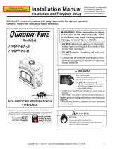
Convection Air Manifold
The convection air manifold is assembled on site and attached to the top of the fireplace. It directs
the hot convection air out of the fireplace and into the room.
* When using the included upper framing members the manifold outlet will be 6-1/2” below the header.
This is the most common installation, placing the outlet at the tallest position. If you wish to make this
dimension lower, you may supply longer pieces of non-combustible framing to place the outlet in a
lower position.
** When the header is placed between 116-1/2” and 92-1/2” above the base of the fireplace, the
supplied lower framing members are installed without modification. If you wish to place the header
between 92-1/2” and 78-1/2”, the lower framing members will need to be cut down in length (use hack
saw, nail-clippers, etc.).
42 Apex CF
Fireplace
Min. 3-1/2"
Lower Framing (included)
Upper Convection Manifold
6-1/2" *
Max. 116-1/2"
Min. 78-1/2" **
Lower Convection Manifold
5" Alum. Flex Duct (included
)
Framing Header
Celing
C
onvection Air Outlet
Upper Framing (included)

14 Installation (for qualified installers only)
© Travis Industries 8/24/2020 - 1450 42 Apex CF
Chase Ventilation (REQUIRED)
WARNING: The chase must be ventilated in accordance with the requirements listed below
to allow for proper fireplace cooling. Failure to do this will create a severe fire risk.
The chase (fireplace enclosure) circulates room air. We recommend dry-walling the interior of the
enclosure or using suitable means to prevent dust or building debris from being circulated into the
room. Plastic sheeting may not be used in place of dry wall.
Chase Ventilation Overview
The chase may be ventilated from the sides (see “a” below) or from the front (see “b” and “c” below).
b
c
a
a

Installation (for qualified installers only) 15
© Travis Industries 8/24/2020 - 1450 42 Apex CF
Chase Ventilation Grills
Use the included grill(s) to ventilate the chase (and fireplace). These grills provide a 50 square inch
opening (free air) to the chase. If alternative grills are desired, they must provide a minimum 50
square inches of free air to the fireplace (contact your dealer for details).
Dimensions
Height
(a)
Width
(b)
Depth
(c)
Min.
Framing
Height
Min.
Framing
Width
Front Ventilation Grill
3-3/4" 38" 1-1/8" 2-1/2" 36"
Small Ventilation Grill
4" 16-1/4" 4-5/8" 2-3/4" 14-3/8"
The grills must be attached directly to the chase cavity.
The included grills use ¼” screen to prevent debris, etc. from entering the chase.
Do not place any items inside the included ventilation grills. Grills should not be placed inside
shelving or near a location where it would become blocked by furniture or other items.
The chase air is drawn from the grills and exits a built-in channel on the upper manifold.
The ventilation air for the chase MUST be drawn from the same room containing the fireplace.
a
b
c

16 Installation (for qualified installers only)
© Travis Industries 8/24/2020 - 1450 42 Apex CF
Chase Ventilation – Front Configuration
If ventilation is provided from the front, you must remove both front inlet knockouts located under the
door opening. The ventilation air passes through the front of the fireplace and exits through the
convection air outlet. In addition, some of this air passes out of the side vents and ventilates the
chase.
When ventilating through the front, the grill is either placed directly on the fireplace or installed into a
raised non-combustible hearth. This hearth must be hollow and able to freely convey air to the
fireplace.
NOTE: If supports are provided in front of these knockouts, these supports must not limit the air
opening to less than 50 square inches.
For front configurations, you must use the large grill (38” x 3-3/4” outside dim.), or both small grills
(16-1/4” x 4” outside dim.), or equivalent free air opening (see note above).
b
c
a

Installation (for qualified installers only) 17
© Travis Industries 8/24/2020 - 1450 42 Apex CF
Chase Ventilation – Side Configuration
If ventilation is provided from the side, you must leave a 2” air gap to the both sides of the fireplace
(see illustration below). The ventilation air passes from the grills, through the chase, into the side
vents and exits through the convection air outlet.
When ventilating from the sides, you must use both small grills (16-1/4” x 4” outside dim.), or
equivalent free air opening (see note above). One grill must be placed on each side of the fireplace.
Vertically, the grills must be placed within 24” of the base of the fireplace (see illustration below).
If placed on a side wall, the grills must be placed directly to the side of the fireplace.
If placed on the front wall, the grills must be placed within 12” of the fireplace.
MIn. 2"
M
ax.. 5-1/2"
This shaded area on both sides of the fireplace must be left
unobstructed when using the side chase ventilation configuration.
TOP OF FIREPLACE

18 Installation (for qualified installers only)
© Travis Industries 8/24/2020 - 1450 42 Apex CF
Raised Fireplaces
The fireplace (and hearth, if desired) may be placed on a platform designed to support the fireplace
and vent (approximately 600 lbs.). See illustration below.
The ceiling in front of the fireplace must be a minimum 82” from the base of the fireplace.
42 Apex CF
Fireplace
Min. 3-1/2"
Min. 82"
Framing Heade
r
Celing
Min. 6-1/2"
Convection Air Outlet

Installation (for qualified installers only) 19
© Travis Industries 8/24/2020 - 1450 42 Apex CF
Approved Chimney
This fireplace requires one of two types of chimney (no exceptions – do not intermix):
Air-Cooled Chimney
- Use Travis Industries air cooled pipe only. Part
numbers are listed in the section “Air Cooled
Chimney”.
- This chimney requires the use of the air-cooled
starter section and cooling duct inlet (see the
section “Air Cooled Chimney” for details).
Insulated Chimney
- Security ASHT+ Chimney
(available from Travis Industries or Security)
(use 98900290 Anchor Plate)
- Alternative Manufacturers
(see the section starting on page 18 for details)
The entire chimney system must be installed to meet all local requirements as well as those
requirements listed by the chimney manufacturer. Depending on the manufacturer and where the
chimney is to be installed, chimney supports, roof braces, radiation shields, attic insulation shields,
attic enclosures, spark arrestors, locking bands, etcetera, may be required as part of the chimney
system. The manufacturer's installation instructions, which are reviewed by the listing agency,
specifies when and where each of these components must be used. Follow the manufacturer's
instructions for the use of flashing and an adjustable storm collar at the roof line to prevent water from
entering the house. Manufacturers require that chimneys extending beyond a certain height above
the roof (typically above 5') must be braced.

20 Installation (for qualified installers only)
© Travis Industries 8/24/2020 - 1450 42 Apex CF
Air Cooled Chimney Requirements (8” Inner Dia., 12” Outer Dia.)
Part Numbers (available through Travis Industries)
Chimney Components Part #
Anchor Plate – Air Cooled Chimney - REQUIRED
98900016
Cooling Duct Kit -6” Diameter - REQUIRED
98900108
48” Chimney Section 98900001
36" Chimney Section 98900002
24" Chimney Section 98900003
18" Chimney Section 98900004
12" Chimney Section 98900005
30° Offsets / Elbows (Qty 2) 98900006
Firestop (90°) 98900007
Firestop (30° - for angled sections) 98900008
Storm Collar 98900009
Round Termination Cap 98900010
Flashing 0-6/12 (for flat roofs up to 6/12 pitch - 26.5°) 98900011
Flashing 7-12/12 (for roofs 6/12 pitch to 12/12 – 26.5° to 45°) 98900012
Attic Insulation Shield 98900015
Anchor Plate Installation
The air-cooled chimney requires an anchor plate that includes a cooling duct inlet. Attach the anchor
plate to the top of the fireplace with the four included sheet-metal screws (see illustration below). The
cooling duct inlet can be directed to any direction (typically it is directed to the right rear).
Seal the fireplace connection with high-temperature silicone.
Seal the flue liner with furnace cement.
High-Temperature
Silicone
Use high-temperature silicone to
seal the anchor plate.
Furnace Cement
/