Page is loading ...

OPERATION AND MAINTENANCE MANUAL
120V/60HZ
BLIZZARD
AVALANCHE
GLACIER
CS518VD
CS518VDTB2
CS6361D
CS636VD
CS650VD


CONTENTS
1.0 INTRODUCTION .................................................................................................................................................4
2.0 UNPACKING YOUR COOL-SPACE UNIT ..........................................................................................................4
3.0 SET-UP OF THE COOL-SPACE UNIT ................................................................................................................4
3.1 Connecting the water supply ................................................................................................................................ 4
3.2 Connecting the electrical supply ......................................................................................................................... 5
4.0 OPERATING PROCEDURES ...............................................................................................................................6
4.1 Filling the unit with water ....................................................................................................................................... 6
4.2 Starting the Fan.......................................................................................................................................................... 6
4.3 Starting the Pump and Adjusting the Water Flow ......................................................................................... 6
4.4 Intuitive Control Panel™ Operation ..................................................................................................................... 7
5.0 MAINTENANCE AND STORAGE.......................................................................................................................8
5.1 Removing the cooling media to access the inside of the unit ................................................................... 8
5.2 Daily maintenance .................................................................................................................................................... 8
5.3 Periodic maintenance .............................................................................................................................................. 8
5.4 Storage .......................................................................................................................................................................... 8
6.0 TROUBLESHOOTING/REPAIR ..........................................................................................................................9
6.1 Troubleshooting ......................................................................................................................................................... 9
6.2 Troubleshooting Guides .......................................................................................................................................10
6.3 Fan Repair Procedures ........................................................................................................................................... 12
6.4 Pump Repair Procedures ...................................................................................................................................... 13
6.5 Technical support .................................................................................................................................................... 13
7.0 WARRANTY ........................................................................................................................................................ 14
7.1 Warranty Form .......................................................................................................................................................... 14
7.2 Warranty Parts .......................................................................................................................................................... 14
7.3 Optional Accessories and Replacement Parts ................................................................................................ 14
Due to continuous product innovations, we reserve the right to change product specication without due notice.

Page 4
SIGNAL WORD DEFINITIONS
!
DANGER
DANGER indicates an imminently hazardous situation which, if not avoided, WILL
result in death or serious injury.
WARNING
!
WARNING indicates a potentially hazardous situation which, if not avoided, COULD
result in death or serious injury.
!
CAUTION
CAUTION indicates a potentially hazardous situation which, if not avoided, MAY result
in minor or moderate injury.
IMPORTANT
IMPORTANT indicates a potentially hazardous situation which, if not avoided, MAY
result in property damage.
1.0 INTRODUCTION
COOL-SPACE is a patented and registered Trademark of Hale Industries, Inc. and manufactured in Indiana.
The COOL-SPACE unit is a compact, self-contained, high-eciency portable evaporative cooler.
2.0 UNPACKING YOUR COOLSPACE UNIT
IMPORTANT
Carefully examine the carton for damage before opening. If the carton is damaged notify the shipping company
immediately.
3.0 SETUP OF THE COOLSPACE UNIT
The COOL-SPACE unit is factory tested and ready to use. The unit should be placed on a level surface, and the casters
locked to prevent inadvertent movement. Follow instructions below to connect water and electrical supply.
3.1 CONNECTING THE WATER SUPPLY
!
CAUTION
Do not connect the COOL-SPACE unit to any water source where water pressure exceeds 120 psi. This will cause
permanent damage to the unit.
The COOL-SPACE unit comes equipped with a female garden hose water source connection. Attach the unit to a
standard garden hose outlet for a water source. It is not recommended that the unit be attached to any water source
with operating pressures above 120 psi. Use a standard garden hose (not provided) to connect the tank to the cooler.

Page 5
3.0 SETUP
3.2 CONNECTING THE ELECTRICAL SUPPLY
IMPORTANT
The COOL-SPACE unit should be plugged into a fused or circuit breaker protected 15 amp, 120 volt, and 60 Hz circuit.
All models utilize standard 120-volt power supply. The unit should be plugged into a fused or circuit breaker protected
15 amp, 120 volt, 60 Hz circuit.
Table 1 shows the amperage requirements for the specic models. If an extension cord is required, refer to Table 2 for
the proper 3-conductor heavy-duty cord required.
!
CAUTION
Do not exceed the amperage ratings of the extension cord. Undersized extension cords result in excessive drops
in voltage, which cause the electric motors to generate excessive heat. This condition results in inecient motor
operation and premature motor failure, WHICH WILL VOID THE WARRANTY.
AMPERAGE REQUIREMENTS
MODEL NUMBER VOLTS ± 10% FREQUENCY (Hz) RUNNING AMPS
CS5-18-VD 120 60 4
CS5-18-V D-TB2 120 60 4
CS6-36-1D 120 60 7.6
CS6-36-VD 120 60 7.6
CS6-50-VD 120 60 9.3
Table 1: Electrical Requirements
3-CONDUCTOR HEAVY- DUTY EXTENSION CORD REQUIREMENTS
LENGTH
(Ft)
CORD SIZE
16 GA 14 GA 12 GA 10 GA
0-50 13 A 18 A 25 A 30 A
50-100 10 A 13 A 18 A 25 A
Table 2: Cord Size Requirements
IMPORTANT
BLIZZARD-50 (SCS6-50-VD) models can not be connected to a GFCI outlet.

Page 6
4.0 OPERATING PROCEDURES
There are 3 factors to consider when determining where to place the COOL-SPACE unit.
1. Fresh air supply: The inlet side of the unit (pad side) requires a constant, uninterrupted supply of fresh air for
maximum performance. A distance of 3 feet clear space to any obstructions at the rear or inlet side of the unit is
recommended.
2. Discharge air ow: The cool air discharged from the unit should be free of obstruction to allow the air to circulate
in order to maximize the cooling zone.
3. Ventilation: In order to operate at maximum eectiveness, it is helpful to have provisions to remove the air
discharged from the COOL-SPACE unit from the cooling area. This ensures that the COOL-SPACE unit does not
recirculate air that has already been through the evaporative cooling process.
The unit must be placed on a level surface to operate correctly. Units create an oval shaped air pattern. Obstacles such
as racks and workbenches may interfere with the air ow. An attempt should be made to locate the unit in such a
manner that interruption of the air pattern is held to a minimum. Multiple units may be required to cover larger areas.
4.1 FILLING THE UNIT WITH WATER
Once the COOL-SPACE unit has been connected to a water source as described in 3.1, turn the water supply valve on
and the unit will ll with water. The oat valve will shut o the water ow when the sump is full.
4.2 STARTING THE FAN
Set the fan switch to the “ON” position and adjust the speed to your preferred setting.
4.3 STARTING THE PUMP AND ADJUSTING THE WATER FLOW
The cooling media in your new unit will take some time to become completely saturated. During this time an odor may
emanate from them. Flush the pads with the Flow Control Valve as far open as possible - without spilling water onto
the oor - for at least 12 hours. This will ensure the best eciency of your COOL-SPACE unit. During this time, the smell
should also dissipate. For best results change the water in the reservoir frequently.
Once your pads are fully ushed
1. Fill reservoir with water
2. Turn on fan
3. Adjust water ow with Flow Control Valve until water streams over pads
Do not ood the pads with water. You should see several dry streaks on the face of the pads 1-2 in. wide. If dry
streaks grow wider, adjust ow to allow more water.
!
CAUTION
Prolonged use of hard water without proper water treatment will create mineral deposit build up causing the pump
to fail which is NOT COVERED BY WARRANTY
IMPORTANT
Pump is equipped with LOW WATER CUT OFF which may take up to 5 minutes to reset each time.

Page 7
4.0 OPERATING PROCEDURES
4.4 INTUITIVE CONTROL PANEL™ OPERATION
The BLIZZARD-50 comes equipped with the Intuitive Control Panel™.
Switches machine between auto and
manual mode
In Auto Mode
• Indicator light will be on
• Machine will run when motion is detected
• When no motion detected, machine will
run for 10 minutes and then shut down
Puts machine into shutdown mode
• When pressed the pump shuts off and the
fan will continue to run for 15 minutes and
then shut down
• Works in auto and manual mode
Turns machine on and off
• Default Speed is 6
• Press to increase speed
• Press to decrease speed
Turns fan on and off in manual mode
Turns pump on and off in manual mode
Fan Pump Auto/Manual
Mode
15 Min.
Countdown
Timer
Remote
Sensor
Power Indicator
Red Light - Power Connected
Green Light - Power On
Low Water Indicator
Power
On/Off
Fan
REM

Page 8
5.0 MAINTENANCE AND STORAGE
!
WARNING
ELECTRICAL SHOCK HAZARD
Disconnect the power supply before performing any service or maintenance.
Failure to do so may result in serious injury or death.
5.1 REMOVING THE COOLING MEDIA TO ACCESS THE INSIDE OF THE UNIT
In order to perform any maintenance on internal components, the cooling pads must be removed to access the inside
of the unit.
1. Remove the bolts connecting the pad retainer bar (pad-side) from the housing.
2. Remove top pads on CS6-36 and CS6-50 units.
3. Starting with the center pad(s), tilt pads from the top; lift out of the unit.
NOTE: Reinstall pads correctly according to the markings on the pads.
5.2 DAILY MAINTENANCE
IMPORTANT
When shutting down the COOL-SPACE unit at the end of each use, the pump should be turned o approximately 15
minutes before the fan is turned o. This will allow the pads to drain and dry out. To avoid disguring the housing the
unit should be drained after every use. These simple guidelines will ensure long and ecient pad life as well as help to
control mildew and bacteria growth, and unit longevity.
5.3 PERIODIC MAINTENANCE
Depending on how often the COOL-SPACE unit operates, this procedure should be performed anywhere from every
week for heavy use to monthly for light use. Shut down the unit and drain the water sump. The cooling pads act as
a ltering agent and remove dust and other particles from the incoming air stream. These particles will ow into the
sump and collect there. Water impurities in the water will also collect in the sump. Maintenance tablets are available at
www.cool-space.com.
DRAINING THE WATER SUMP
1. Close the water ow valve and open the drain valve or remove drain plug located at bottom of reservoir.
2. Run pump until sump is dry then immediately shut o pump.
3. Turn unit o and disconnect the power supply.
4. Remove cooling pads, refer to section 5.1.
5. Clean out reservoir with either a towel or wet/dry vacuum.
6. Remove the water spray bar and its plug. Insure holes are free of debris.
7. Reinstall pads and pad retainer.
To keep the COOL-SPACE unit operating at peak eciency, ensure that the cooling pads are kept clean and dust-free.
Dust and other particles have an adverse eect on the media’s ability to introduce water into the air stream. If the pad
surface becomes dirty or dusty, clean with a soft brush and water.
5.4 STORAGE
1. Remove the pads, as described in section 5.1
2. Clean with a soft brush and water to remove dust and debris (never use bleach)
3. Drain sump using procedure described in section 5.3 and wipe dry
4. Store in a dry area and cover to prevent dust build-up. Covers can be found online at www.cool-space.com.

Page 9
6.0 TROUBLESHOOTING/REPAIR
!
WARNING
ELECTRICAL SHOCK HAZARD
Disconnect the power supply before performing any service or maintenance.
Failure to do so may result in serious injury or death.
6.1 TROUBLESHOOTING
The COOL-SPACE unit consists of three systems: the fan, water distribution and pump. It is important to determine
which system of the COOL-SPACE unit the problem is associated with. This may not always be obvious, in that certain
problems may be associated with more than one system.
When determining which system has a problem, you must dene the associated problem, (e.g. the pump is not
running). Although this might seem a bit simplied, several things may cause this particular problem. So while dening
the problem, a careful check of all systems should be made to fully understand the extent of the problem.
If you have a complete understanding of all of the systems of the COOL-SPACE unit and how they depend on each
other, it will be simple to dene and solve any problem.
NECESSARY TOOLS:
Although the COOL-SPACE unit is designed to be simple to maintain, it will be necessary to have some basic hand tools
(screwdrivers, pliers, adjustable wrenches, etc.) as well as a volt/ohm meter when troubleshooting the electrical system.
!
CAUTION
Please use caution when troubleshooting or repairing all electrical components. Be certain that all power is
disconnected from the COOL-SPACE unit before the cooling pads or fan guard are removed to gain access to the fan.

Page 10
FAN SYSTEM
FAN WON’T RUN AND MAKES NO SOUND
Check power cord, extension cord, switches, circuit
breaker
•Reconnect power or extension cord; Reset breaker
FAN WON’T RUN MAKES HUMMING SOUND
Blade in contact with shroud
Re-center blade hub
Motor stalled (will not turn by hand)
Replace motor
BREAKER TRIPS OR FUSE BLOWS WHEN FAN IS
STARTED
Motor stall
Replace motor
Check power source for min. 120 volt/10 amp
Upgrade power supply
Extension cord gauge too small
Replace with heavier cord
MOTOR OVERHEATS, SHUTS OFF AND RESTARTS
SEVERAL MINUTES LATER
Extension cord gauge too small
Replace with heavier cord
Inlet air obstructed or too close to wall
Provide minimum 3 feet inlet clearance
Faulty motor
Replace motor
FAN MOTOR WON’T RUN SWITCH MAKES SOFT
CLICKING SOUND
Ensure that switch is making good contact
Replace switch if needed
FAN BLADE DOESN’T TURN UNIT MAKES
SQUEALING SOUND
Motor stall (will not turn by hand)
Replace motor
FAN WILL NOT REACH SPEED BUT TURNS AND
MAKES HUMMING SOUND
Check Capacitor (where visible) and motor electrical
connections
Replace capacitor or motor
Extension cord gauge too small
Replace with heavier cord
INTUITIVE CONTROL PANEL ERROR CODES
E1 OVER CURRENT PROTECTION
Current draw too high
•Check extension cord size
•Check motor spins freely
•Check airow not obstructed
•Replace motor
E2 OVER VOLTAGE PROTECTION
Supply voltage too high ≥ 132V
•Try dierent circuit
•Install Voltage Regulator
E3 LOW VOLTAGE PROTECTION
Supply voltage too low ≤ 108V
•Try dierent circuit
•Install voltage regulator
E4 LOSS OF PHASE PROTECTION
Motor phase imbalance
Loose or disconnected motor wire, Replace motor
E7 OVERLOAD PROTECTION
Motor running too hot
Check extension cord size, Check motor spins freely,
Check airow not obstructed, Replace motor
F6 COMMUNICATION FAILURE
Failure of communication between control panel and
control board
Check connection of control cable, Check control cable
not broken
6.0 TROUBLESHOOTING/REPAIR
6.2 TROUBLESHOOTING GUIDES

Pag e 11
WATER SYSTEM
The water distribution system consists of two (2)
assemblies:
1. The Water Inlet Assembly
•Brass bulkhead tting
•Float valve assembly
2. The Hose and Valve Assembly
•Spray Bar Assembly
•Valve Assembly
•Connection Hose
FLOOR AT SIDE OF UNIT IS WET
Water inlet hose is loose at supply hose or inlet hose is
loose at bulkhead tting.
Tighten connections and/or replace hose washers.
UNIT OVERFLOWS FROM RESERVOIR OR IS
SPITTING WATER THROUGH FAN
Float valve hose is loose at bulkhead tting or at oat
valve.
Tighten connections and/or replace hose washers
Water pressure is too high to allow oat valve to
shuto (120psi max)
Reduce water pressure by adding an inline reducer
Float valve not properly seated
Check all hoses for leaks
WATER SPITTING FROM THE UNIT
Check The Hose and Valve Assembly
•Reduce ow control setting
•Replace cracked hose and valve assembly
•Tighten hose connections
•Adjust spray bar
•Ensure pads were installed correctly
WATER LEAKING FROM DRAIN VALVE
Check for worn washer, stem or open drain valve
•Replace washer
•Replace drain valve
TOO MANY DRY STREAKS ON THE PADS
Check for blocked holes in the spray bar or adjust
water ow
•Remove spray bar, remove plug and clean tube and
holes
•Open water ow control valve
PUMP
PUMP MOTOR WILL NOT RUN WHEN SWITCH IS
TURNED ON
Turn fan on to check for power
•If fan doesn’t start check breaker and cord plug-in
•If fan does start; check for power to and through
pump switch (when turned on)
Ensure water level is high enough to make the low-
water cut-o circuit
Fill water reservoir
PUMP MOTOR HUMS WHEN SWITCH IS TURNED
ON, BUT DOES NOT PUMP WATER
Obstruction in impellor
Remove object(s)
Pump motor failure
Replace pump
BREAKER TRIPS OR FUSE BLOWS WHEN SWITCH IS
TURNED ON
Check power cord length and breaker rating
Refer to page (2) for unit amperage draw and to
determine required cord gauge
Check for locked-up pump
Replace pump
PUMP RUNS BUT DOES NOT PUMP WATER
Air lock in outlet side of pump
Turn o and on to bleed
Ensure the impellor is turning in pump
If not, replace pump
6.0 TROUBLESHOOTING/REPAIR

Page 12
6.0 TROUBLESHOOTING/REPAIR
6.3 FAN REPAIR PROCEDURES
!
CAUTION
Repairs should be performed by a qualied technician!
!
WARNING
ELECTRICAL SHOCK HAZARD
Disconnect the power supply before performing any service or maintenance.
Failure to do so may result in serious injury or death.
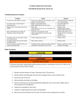
FAN MOTOR REPLACEMENT FOR CS518VD, CS518VDTB2
1. Remove cooling pads (see section 5.1 for pad removal instructions)
2. Remove the black motor wiring plate and disconnect motor wires. (Mark each wire with a marker or marker tape
to allow for easy matching when installing new motor.
3. Remove the (4) nuts and bolts that mount the motor, fan, and support braces (complete fan assembly).
4. Replace new fan assembly.
5. Secure with (4) nuts and bolts.
6. Replace any wire ties that were removed when taking out the old fan assembly.
7. Replace the black motor wiring plate.
8. Reinstall pads and connect power
FAN MOTOR REPLACEMENT FOR CS6361D, CS636VD, CS650VD
1. Remove cap from bottom of motor. Disconnect wires. Clip wire ties.
2. Remove (4) fan mounting bolts from the front. (Support fan to ensure it doesn’t fall.)
3. Pull the fan out of the unit.
4. Remove blade mounting nut and blade.
5. Remove mounting arms by loosening (8) bolts holding the arms to the motor. (Make note of arms positions for
reinstallation.)
6. Install arms and blade on new motor.
7. Install fan in opening and secure with mounting bolts.
8. Reconnect wires and attach cord to motor arm with wire ties to keep them out of fan.

Page 13
6.0 TROUBLESHOOTING/REPAIR
6.4 PUMP REPAIR PROCEDURES
!
CAUTION
Repairs should be performed by a qualied technician!
!
WARNING
ELECTRICAL SHOCK HAZARD
Disconnect the power supply before performing any service or maintenance.
Failure to do so may result in serious injury or death.
PUMP REPLACEMENT FOR CS518VDTB2
1. Loosen PVC Union
2. Remove pump and PVC pipe
3. Unplug the cord from the top of the pump by removing 2 screws
4. Unscrew PVC pipe from the pump
5. Reverse steps 1-4 to reinstall the new pump
6. Reinstall cooling pads and guards, reconnect power, and test pump
PUMP REPLACEMENT FOR CS518VD, CS6361D, CS636VD, CS650VD
1. Unscrew tting from pump
2. Unplug the cord from the top of the pump by removing (2) screws
3. Remove pump from water sump and install new pump
4. Reverse the above procedures to reconnect the wiring, lift pump bracket and reconnect the hose. Secure wires
to fan frame with wire ties to clear the fan blades. Be sure to position the plug correctly.
5. Reinstall cooling pads and guards, reconnect power and test pump.
6.5 TECHNICAL SUPPORT
Technical support and service are available directly from your distributor or the COOL-SPACE Technical Support Line at
1-800-557-5716, support@cool-space.com or www.cool-space.com.

7.0 WARRANTY
The limited warranty is sixty (60) months from date of invoice. Refer to the manufacturer’s Warranty Policy for details.
(Applies to units purchased after January 1, 2017)
7.1 WARRANTY FORM
You must register your COOL-SPACE Portable Evaporative Cooler within fteen (15) days of initial purchase to validate
your cooler’s warranty. You may register online at www.cool-space.com.
7.2 WARRANTY PARTS
Warranty replacement parts are available through your local distributor or supplier where you purchased your COOL-
SPACE unit. If you have any questions or concerns, please contact us direct at 1-800-557-5716 or at sales@cool-space.
com. Please have your model number and serial number ready.
IMPORTANT
DO NOT DISCARD FAULTY PARTS Check with the Manufacturer as they may need to be returned for warranty credit.
7.3 OPTIONAL ACCESSORIES AND REPLACEMENT PARTS
Accessories and replacement parts are available from your local distributor or supplier or they can be found online at
www.cool-space.com.


315 N Madison Street
Fortville, IN 46040
317-577-0417 · 800-557-5716
support@cool-space.com
COOL-SPACE.com
CS-MAN-ALL60HZ 03252019al
/