Ames Fire & Waterworks DERINGER 50 GPM 8 Owner's manual

Type
Owner's manual
User Guide
Deringer
For all Deringer Series Valves
Important Installation
Information Read before
installing
For additional detailed maintenance and repair instructions,
including videos, visit BackflowDirect.com/downloads.html
For Deringer Models 20/20X/30/30X/40/40X/50/50X
Install with FLEX Couplings or Flange Adapters Only.
DO NOT use RIGID Couplings or Groove Reducing
Couplings!
Micro Bypass Orientation
Please follow these instructions to properly orient the
meters on the Deringer 30 & 50 micro bypass assemblies:
1. The Deringer water
meters are rotated 90
degrees during shipping
to protect the plastic
register from damage.
2. Using an adjustable
wrench loosen the meter
couplings on both sides
of the meter and rotate
the meter into the proper
orientation.
3. Using an adjustable
wrench tighten the meter
couplings on both sides
of the meter (proper
meter orientation).
Flange
Adapters
FLEX
Couplings
RIGID
Couplings
Groove Reducing
Couplings
For Deringer Models 30/30X/30G/30GX/50/50X/50G/50GX
FLOW
UserGuide-A-Deringer
WARNING: Make sure to thoroughly flush out water lines prior to installation of a Deringer. If water lines are NOT thoroughly flushed, debris will damage the check and
relief valves and will not be covered under warranty.
WARNING
!
WARNING
!
Read this manual BEFORE using this equipment.
Failure to read and follow all safety and use information can
result in death, serious personal injury, property damage, or
damage to the equipment.
Keep this manual for future reference.
You are required to consult the local building and plumbing
codes prior to installation. If the information in this manual
is not consistent with local building or plumbing codes,
the local codes should be followed. Inquire with governing
authorities for additional local requirements.
WARNING
!
2
UserGuide-A-Deringer 2018 © 2020 Watts
Relief Valve Installation
Please follow these instructions to properly install the relief valve to the main body:
For Deringer Models 40/40X/40G/40GX/50/50X/50G/50GX
FLOW
1. Before installing the
relief valve, make sure
the O-Ring is in the
groove on the top of the
relief valve. Apply a small
coating of lubricant to
O-Ring.
2. Mount the relief valve
to the relief valve port on
the bottom side of the
main valve body.
3. Use a 9/16” wrench
to attach the two relief
valve mounting bolts.
Tighten both bolts.
4. Use an adjustable
wrench to connect the
relief valve sensing line
to the sensing line body
coupler.
For additional detailed maintenance and repair instructions,
including videos, visit BackflowDirect.com/downloads.html
3
UserGuide-A-Deringer 2018 © 2020 Watts
1
2" NPT
For Deringer Models 20/20X/30/30X/40/40X/50/50X
1. The supervisory switch assembly contains two single
pole, double throw, pre-wired switches. A primary and
an auxiliary.
2. Switch ratings:
10 amps @ 125 or 250 VAC/60 Hz
0.5 amps @ 125 VDC
0.25 amps @ 250 VDC
3. Primary and Auxilary, supervise the valve in the “OPEN”
position.
4. Primary has two #18 insulated wires per terminal, permit-
ting complete supervision of leads. Auxiliary has one #18
insulated wire per terminal. This double circuit allows for
the operation of two separate electrical devices (audible
alarms, indicating lights, etc.) in close proximity to the
valve installation.
5. A #14 insulated ground lead (green) is provided
Primary (S1) For connection to a supervisory circuit of
a UL Listed alarm control panel
Auxilary (S2) For connection to auxiliary devices per
the authority having jurisdiction
Gear Box Wiring Installation
NOTE: The below diagram shows a connection between terminals (S1: Yellow / S2: Yellow with Orange Stripe) and the normally Open
Terminals (S1: Brown / S2: Brown with Orange Stripe). In this example the signal switch will remain open (No current through switch)
as long as the valve remains Fully Opened. Once the Valve begins to close the signal switch will change from open to close (current
will flow through switch). Only S1 (two leads per terminal) may be connected to the fire alarm control panel. The connection of the
alarm switch wiring shall be in accordance with NFPA 72 and the auxiliary switch per NAPA 70 (NEC). Remember to cap off any
unused wire and that your conduit connections are water tight.
Normally Closed: (2) Blue
Normally Open: (2) Brown
Common: (2) Yellow
Normally Closed: Blue with Orange Stripe
Normally Open: Brown with Orange Stripe
Common: Yellow with Orange Stripe
S1
S2
For additional detailed maintenance and repair instructions,
including videos, visit BackflowDirect.com/downloads.html
Limited Warranty: Ames Fire & Waterworks (the “Company”) warrants each product to be free from defects in material and workmanship under normal usage for a period of one year from the date
of original shipment. In the event of such defects within the warranty period, the Company will, at its option, replace or recondition the product without charge.
THE WARRANTY SET FORTH HEREIN IS GIVEN EXPRESSLY AND IS THE ONLY WARRANTY GIVEN BY THE COMPANY WITH RESPECT TO THE PRODUCT. THE COMPANY MAKES NO
OTHER WARRANTIES, EXPRESS OR IMPLIED. THE COMPANY HEREBY SPECIFICALLY DISCLAIMS ALL OTHER WARRANTIES, EXPRESS OR IMPLIED, INCLUDING BUT NOT LIMITED TO
THE IMPLIED WARRANTIES OF MERCHANTABILITY AND FITNESS FOR A PARTICULAR PURPOSE.
The remedy described in the first paragraph of this warranty shall constitute the sole and exclusive remedy for breach of warranty, and the Company shall not be responsible for any incidental, special
or consequential damages, including without limitation, lost profits or the cost of repairing or replacing other property which is damaged if this product does not work properly, other costs resulting from
labor charges, delays, vandalism, negligence, fouling caused by foreign material, damage from adverse water conditions, chemical, or any other circumstances over which the Company has no control.
This warranty shall be invalidated by any abuse, misuse, misapplication, improper installation or improper maintenance or alteration of the product.
Some States do not allow limitations on how long an implied warranty lasts, and some States do not allow the exclusion or limitation of incidental or consequential damages. Therefore the
above limitations may not apply to you. This Limited Warranty gives you specific legal rights, and you may have other rights that vary from State to State. You should consult applicable state laws to
determine your rights. SO FAR AS IS CONSISTENT WITH APPLICABLE STATE LAW, ANY IMPLIED WARRANTIES THAT MAY NOT BE DISCLAIMED, INCLUDING THE IMPLIED WARRANTIES
OF MERCHANTABILITY AND FITNESS FOR A PARTICULAR PURPOSE, ARE LIMITED IN DURATION TO ONE YEAR FROM THE DATE OF ORIGINAL SHIPMENT.
UserGuide-A-Deringer 2018 EDP# 2916025 © 2020 Watts
USA: Backflow T: (978) 689-6066 • F: (978) 975-8350 • AmesFireWater.com
USA: Control Valves T: (713) 943-0688 • F: (713) 944-9445 • AmesFireWater.com
Canada: T: (888) 208-8927 • F: (888) 479-2887 • AmesFireWater.ca
Latin America: T: (52) 55-4122-0138 • AmesFireWater.com
Air Gap Assembly Applications & Limitations
An Air Gap Assembly (attached to relief Valve) will capture and evacuate
light to moderate water discharge from the Relieve Valve caused by daily
fluctuation in system/supply pressure.
An Air Gap Assembly will NOT capture and evacuate the
Maximum Relief Valve Discharge Rate caused by catastrophic
valve or system failure.
An auxiliary drain (separate and independent of the Air Gap Assembly) is
REQUIRED and MUST be properly sized for the Maximum Relief Valve
Discharge Rate. Ames
®
shall not be responsible for any damage caused
by lack of auxiliary drain, location of auxiliary drain or undersized auxiliary
drain. If the installer does not clearly understand this requirement
DO NOT install the RP/RPDA & Air Gap Assembly.
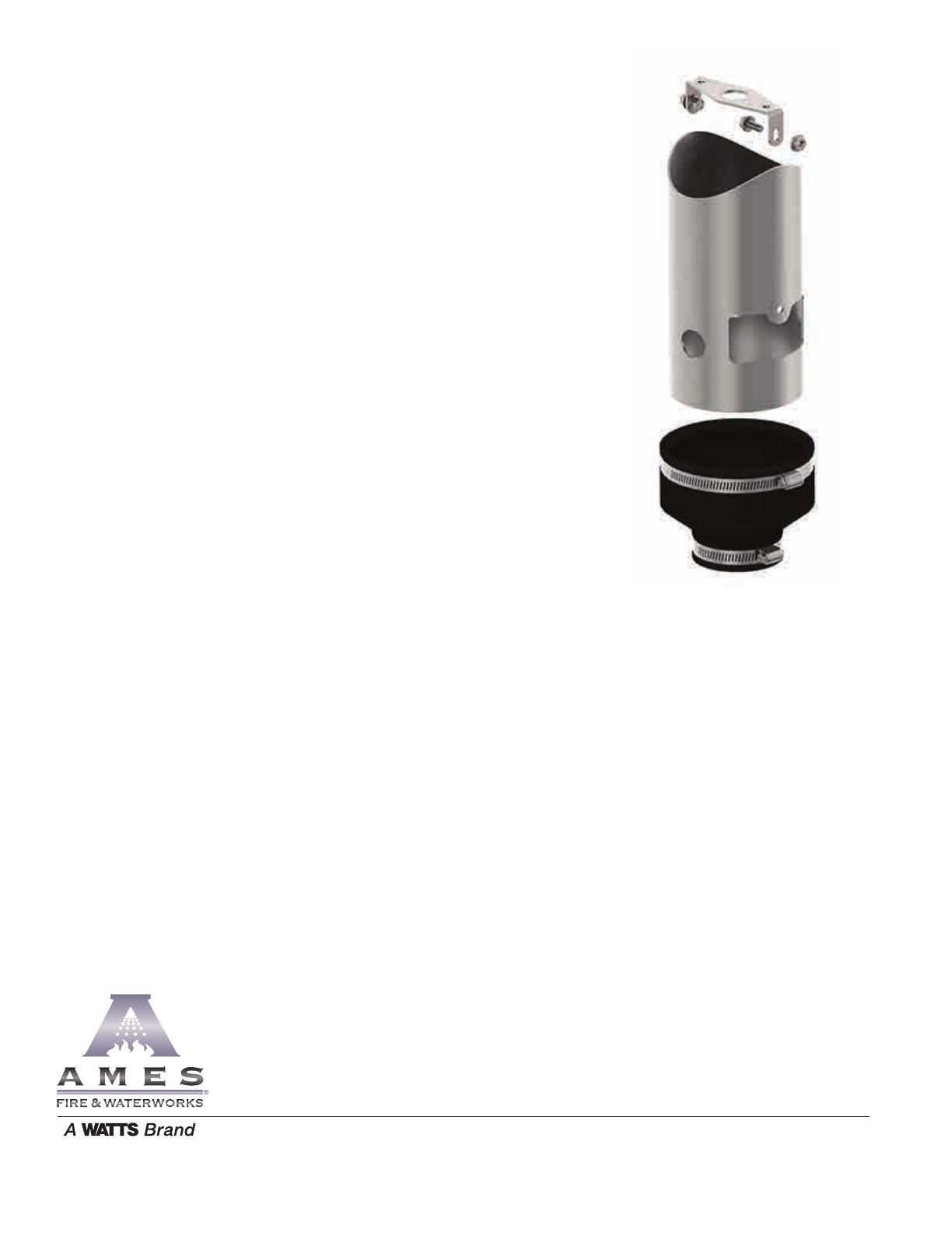
Ames Air Gaps Include:
• Air Gap drain mounting bracket
• Air gap drain shield
• Air Gap drain reducer
• All required hardware
  • Page 1 1
  • Page 2 2
  • Page 3 3
  • Page 4 4

Ames Fire & Waterworks DERINGER 50 GPM 8 Owner's manual

Type
Owner's manual

Ask a question and I''ll find the answer in the document

Finding information in a document is now easier with AI