Page is loading ...

PRACTICAL INSTALLATION TIPS FOR BLACK STAR
CONDENSING UNITS
TIPS FOR
THE INSTALLER
CZ.80.B1.02
Produced by Danfoss G1 advertising agency 02.08 LN.bpv.AO
Danfoss can accept no responsibility for possible errors in catalogues, brochures and other printed material. Danfoss reserves the right to alter its products without notice. This also applies to
products already on order provided that such alterations can be made without subsequential changes being necessary in specifications already agreed.
All trademarks in this material are property of the respective companies. Danfoss and the Danfoss logotype are trademarks of Danfoss A/S. All rights reserved.

3
General considerations when installing Blackstar condensing units . . . . . . . . . . . . . . . . 3
Careful fitting . . . . . . . . . . . . . . . . . . . . . . . . . . . . . . . . . . . . . . . . . . . . . . . . . . . . . . . . . . . . . . . . . 3
Installation . . . . . . . . . . . . . . . . . . . . . . . . . . . . . . . . . . . . . . . . . . . . . . . . . . . . . . . . . . . . . . . . . . . 3
Blackstar tube connections . . . . . . . . . . . . . . . . . . . . . . . . . . . . . . . . . . . . . . . . . . . . . . . . . . . . 4
Impurities and contaminants . . . . . . . . . . . . . . . . . . . . . . . . . . . . . . . . . . . . . . . . . . . . . . . . . . .6
Copper tubing and components . . . . . . . . . . . . . . . . . . . . . . . . . . . . . . . . . . . . . . . . . . . . . . . . 6
Soldering . . . . . . . . . . . . . . . . . . . . . . . . . . . . . . . . . . . . . . . . . . . . . . . . . . . . . . . . . . . . . . . . . . . 7
Silver solder . . . . . . . . . . . . . . . . . . . . . . . . . . . . . . . . . . . . . . . . . . . . . . . . . . . . . . . . . . . . . . . . . . 7
Protective gas . . . . . . . . . . . . . . . . . . . . . . . . . . . . . . . . . . . . . . . . . . . . . . . . . . . . . . . . . . . . . . . . 7
Evacuation and charging . . . . . . . . . . . . . . . . . . . . . . . . . . . . . . . . . . . . . . . . . . . . . . . . . . . . . . 8
Vacuum pump . . . . . . . . . . . . . . . . . . . . . . . . . . . . . . . . . . . . . . . . . . . . . . . . . . . . . . . . . . . . . . . . 8
Charging . . . . . . . . . . . . . . . . . . . . . . . . . . . . . . . . . . . . . . . . . . . . . . . . . . . . . . . . . . . . . . . . . . . . . 8
Exceeding the max. permissible operating charge . . . . . . . . . . . . . . . . . . . . . . . . . . . . . . . . 9
Inspection and setting of safety equipment . . . . . . . . . . . . . . . . . . . . . . . . . . . . . . . . . . . . . . 10
Technical regulations and stipulations . . . . . . . . . . . . . . . . . . . . . . . . . . . . . . . . . . . . . . . . . . 10
Blackstar –air-cooled condensing units for R 134a and R 404A / R 507 . . . . . . . . . . . . . . . . 11
Electrical equipment . . . . . . . . . . . . . . . . . . . . . . . . . . . . . . . . . . . . . . . . . . . . . . . . . . . . . . . . . . 11
Compressor protection . . . . . . . . . . . . . . . . . . . . . . . . . . . . . . . . . . . . . . . . . . . . . . . . . . . . . . . . 12
Fan . . . . . . . . . . . . . . . . . . . . . . . . . . . . . . . . . . . . . . . . . . . . . . . . . . . . . . . . . . . . . . . . . . . . . . . . . . 13
Shut-off valves (N2 and T2 models) . . . . . . . . . . . . . . . . . . . . . . . . . . . . . . . . . . . . . . . . . . . . . 13
Weather-resistant enclosure . . . . . . . . . . . . . . . . . . . . . . . . . . . . . . . . . . . . . . . . . . . . . . . . . . .13
Leakage testing . . . . . . . . . . . . . . . . . . . . . . . . . . . . . . . . . . . . . . . . . . . . . . . . . . . . . . . . . . . . . . . 14
Evacuation and charging . . . . . . . . . . . . . . . . . . . . . . . . . . . . . . . . . . . . . . . . . . . . . . . . . . . . . . 14
Max. permissible refrigerant charge . . . . . . . . . . . . . . . . . . . . . . . . . . . . . . . . . . . . . . . . . . . . 15
Exceeding the max. permissible charge . . . . . . . . . . . . . . . . . . . . . . . . . . . . . . . . . . . . . . . . . 16
Compressor Shell heating . . . . . . . . . . . . . . . . . . . . . . . . . . . . . . . . . . . . . . . . . . . . . . . . . . . . . . 16
»Pumpdown cycle« . . . . . . . . . . . . . . . . . . . . . . . . . . . . . . . . . . . . . . . . . . . . . . . . . . . . . . . . . . . . 17
Max. permissible temperature . . . . . . . . . . . . . . . . . . . . . . . . . . . . . . . . . . . . . . . . . . . . . . . . . 17
Solder Adaptor (FSA) . . . . . . . . . . . . . . . . . . . . . . . . . . . . . . . . . . . . . . . . . . . . . . . . . . . . . . . . . . 19
2
50 Hz • R22 • R134a •
R290 • R404A
This section provides general appli-
cation information on Black Star
condensing units. Subsequent sections
will describe specific details of Black
Star condensing units.
Careful fitting
Industrial refrigeration and air-
condition systems are increasingly
based on hermetic compressors.
Such refrigeration systems make high
demands on design and installation
quality.
General instruction can be found in
»Practical tips« in the folder »Tips for
the installer«, where the most impor-
tant facts and additional information
are repeated.
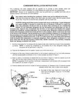
Installation
Black Star condensing units must be
installed in well-ventilated surround-
ings to ensure that there is sufficient
air flow, through the condenser, to
adequately cool the compressor.
In addition, it must be ensured that
discharge air is kept away from the
air intake. When the fan motor is con-
nected, air is drawn towards the
compressor over the condenser. The
condenser must be cleaned regularly
to ensure that the condensing unit
functions optimally.
General considerations when installing
Black Star condensing units
1 × Min. compartment length:
condenser 2 × condenser depth
height

5
4
Compressor
Condenser
Max. 1,5 m
Evaporator
Max. 1,5 m
Max. 5 m
Compressor
Condenser
Evaporator
Max. 30 m
Blackstar tube connections
Tubing runs must be as short and
compact as possible. Low-lying tube
sections where oil can collect (oil
pockets) should be avoided.
1. If the Blackstar condensing unit is
installed at the same height as the
evaporator.
The suction line should be fitted with a
slight downward incline towards the
compressor.
The maximum permissible distance
between the condensing unit and the
evaporator is 30 m.
To ensure return oil flow, the following
suction line dimensions are
recommended:
TL ∅8 mm FR ∅ 10 mm
SC ∅10 mm SC Twin ∅ 16 mm
The following tube dimensions are
recommended for liquid-carrying
lines:
TL ∅6 mm FR ∅6 mm
SC ∅8 mm SC Twin ∅ 10 mm
2. If the Blackstar condensing unit is
installed above the evaporator.
The vertical distance between the
condensing unit and the refrigeration
unit must not exceed 5 m. The length
of tubing between the condensing unit
and the evaporator must not exceed
30 m. Suction lines must incorporate
oil traps taking the form of double bends
at the bottom and top of the line.
The bends must be u-formed at the
bottom of the vertical tube section and
p-formed at the top. The maximum per-
missible distance between bends is
1-1.5 m.
General considerations when installing
Blackstar condensing units
Compressor
Condenser
Max. 1,5 m
Evaporator
Max. 1,5 m
Max.. 5 m
To ensure return oil flow, the following
suction line dimensions are
recommended:
TL ∅8 mm SC 12/15 ∅10 mm
FR ∅10 mm SC Twin ∅6 mm
All others SC ∅12 mm
The following tube dimensions are
recommended for liquid-carrying
lines:
TL ∅6 mm FR ∅6 mm
SC ∅8 mm SC Twin ∅10 mm
3. If the Blackstar condensing unit is
installed below the evaporator.
The vertical distance between the
condensing unit and the evaporator
must not exceed 5 m. The length of
tubing between the condensing unit
and the evaporator must not exceed
30 m. Suction lines must incorporate
oil traps taking the form of double
bends at the bottom and top of the
line. The bends must be u-formed at
the bottom of the vertical tube section
and p-formed at the top. The maximum
permissible distance between bends is
1-1.5 m.
To ensure return oil flow, the following
suction line dimensions are
recommended:
TL ∅8 mm FR ∅10 mm
SC ∅12 mm SC Twin ∅16 mm
The following tube dimensions are
recommended for liquid-carrying
lines:
TL ∅6 mm FR ∅6 mm
SC ∅8 mm SC Twin ∅10 mm
General considerations when installing
Blackstar condensing units

7
6
Silver solder
The most suitable solder is the so-
called silver solder, which is an alloy
of 55% silver, copper, zinc and tin.
The melting point of silver solder is
between 655°C and 755°C.
The coated silver solder contains the
flux necessary to solder the connec-
tion. After soldering, excess flux
should be removed using emery cloth
or a brush to avoid »hidden» leaks.
Silver solder is suitable for soldering
different materials, steel / copper for
example.
Protective gas
On exposure to air, oxidation products
(oxide scale) are immediately formed
at such high soldering temperatures.
The system must therefore be protect-
ed by a flow of gas during soldering.
Direct a light flow of dry inert gas
through the tube. Do not start solder-
ing until all air in the component has
been replaced by gas.
Start the process with a strong flow of
protective gas, and reduce the flow to
a minimum when starting soldering.
This light flow of protective gas must
be maintained throughout the entire
soldering process. Supply oxygen and
gas during soldering. Use a soft flame
and if possible a fork burner.
Do not apply the solder until the melt-
ing temperature has been reached.
Soldering
Impurities and contaminants
Impurities and contaminants are the
most common factors reducing the
reliability and operating life of refri-
geration plants.
During installation the following
impurities can enter the system:
●
Oxide scale from soldering
(oxidation)
●
Flux from soldering
●
Moisture and foreign gases
Copper tubing and components
Only clean and dry copper tubes
should be used for refrigeration plants.
All components must comply with
DIN 8964.
Further information is available in the
quick reference »Blackstar condensing
units, CB.32.Bx.2« if quick adjustment
of the refrigeration controls is necessary.
A well-arranged table in the brochure
shows which refrigeration controls are
required, allowing quick and easy
choice of necessary equipment.
General considerations when installing
Blackstar condensing units

9
8
Exceeding the max. permissible
operating charge
If the refrigerant charge is more than
the permissible operating charge,
precautions must be taken. Heating
the compressor shell is a simple and
fast way of preventing refrigerant mi-
gration during standstill phases.
Crankcase heater can be ordered at
Danfoss. Code.no.: 192H2096.
A »pumpdown cycle« is another
possibility. A solenoid valve controlled
by a thermostat must be installed in
the liquid line. When the solenoid
valve closes, the compressor sucks
on the low-pressure side until the
low-pressure switch cuts out at the
compressor pressure setting.
During a pumpdown cycle, the low-
pressure switch cut-in setting must be
set lower than the refrigerant satura-
tion pressure for the lowest condens-
ing unit and compressor ambient tem-
perature.
SC with shell heating
Evaporator
Sight glass
Filter drier
Expansion valveSolenoid valve
Thermostat
Evacuation and charging
Vacuum pump
The vacuum pump should be able
to remove system pressure to about
0.67 mbar and, preferably, be two-
stage. Moisture, atmospheric air and
protective gas should also be removed.
As far as possible, evacuation of the
condensing unit should be two-sided,
i.e. from suction and pressure sides.
Use the connections on the condensing
unit suction and shut-off valves.
Further details are given in the follow-
ing sections and/or in the section
»Practical tips« in the folder »Tips for
the installer«.
Charging
Charging the system involves the use
of a level or charging cylinder and/or a
balance. Provided a charging valve is
used, the refrigerant can be supplied
(as liquid) through the liquid line.
Otherwise, the refrigerant must be
charged into the system in gas form
through the shut-off valve, with the
compressor running (the vacuum
must be broken first).
Remember that refrigerants R 404A,
R 507 and R 407C are blends.
Refrigerant producers recommend
that R 507 be charged in liquid or gas
form, while R 404A and R 407C must be
charged in liquid form.
It is further recommended that R 404A,
R 507 and R 407C be charged as
described, i.e. using a charging valve.
If the required quantity is not known,
charging must be performed until air
bubbles can no longer be seen in the
sight glass. Here, to ensure normal
operating temperature, the liquid and
suction gas temperatures must be
constantly monitored.
Evacuation and charging

11
10
This folder deals exclusively with
condensing units for operation with
expansion valves. These units are
marked T2, which means that the unit
is fitted with a receiver and two shut-
off valves. Condensing units available
for capillary tube operation, marked
NO or N2, are not dealt with here.
Blackstar condensing units for the
UK market incorporate a fusible plug
according to BS1608.
Electrical equipment
The condensing units are fitted, ready
for wiring up. A terminal box at the
front of the unit contains a board to
which the leads from the refrigeration
system can be connected.
Blackstar – condensing units
for R 134a and R 404A / R 507
Terminal box
Inspection and setting
of safety equipment
The setting and inspection of safety
equipment must be performed me-
chanically and electrically on the
equipment itself – while it is installed
and running. Functions must be
checked with measuring equipment.
Technical regulations and
Standards
The latest regulations and Standards
must followed, e.g.
●
Basic technical safety regulations for
building up, equipping, setting up
and operating refrigeration plant –
DIN 8975 or BS1608
●
EN 60335
●
PED
●
EN 378

13
12
Fan
The fan runs in self-lubricating
bearings and has a large oil reservoir
to ensure maintenance-free operation
for many years. All fan motors have a
built-in winding protector or are
impedance protected.
Marking:
TW = Thermally protected
ZP = Impedance protected
Shut-off valves (N2 and T2 models)
Blackstar condensing units are
equipped with shut-off valves on
suction and pressure sides. Turning
the spindle clockwise shuts off flow to
the soldered connection while flow
between the pressure gauge and flared
connection is established. Turning the
spindle fully counterclockwise shuts
off the pressure gauge connection and
establishes flow between the soldered
connection and the flared connection.
With the spindle in its mid position,
there is flow through all three connec-
tions.
Weather-resistant enclosure
Blackstar condensing units for
installation in the open air must be
protected by an overhead cover or
have a weather-resistant housing.
Blackstar »Outdoor Units« are avail-
able. These are fitted with condensing
units in a weather-resistant housing
and the compressor is heated during
standstill phases.
Cabinets alone:
Single: Code no. 118U4620
TWIN: Code no. 118U4621
Fan motor and blade
Blackstar – condensing units
for R 134a and R 404A / R 507
It is recommended that the two parallel-
connected compressors in TWIN
condensing units be started via a time
relay (Danfoss code number:
117 N 0001).
This gives the condensing unit the
best starting conditions and ensures
minimum load on the mains supply.
Compressors are fitted with an HST
starting system consisting of a start
relay and a start capacitor. The capa-
citor is designed for short-duty cycles
(1.7% ED).
This means in practice that the com-
pressor can be subjected to 10 starts
an hour with a cut-in time of 6 seconds
for each start.
Compressor protection
The fully hermetic compressors have
a built-in winding protector. When this
is activated, the result can be
compressor motor cut-out for up to 45
minutes, until accumulated heat in the
motor has been dissipated. By taking
resistance measurements it is possible
to establish whether the winding pro-
tector has been activated or a winding
has broken.
Zeitverzögerungsrelay
Blackstar – condensing units
for R 134a and R 404A / R 507

15
14
Max. permissible refrigerant charge
Blackstar condensing unit
Blackstar – condensing units
for R 134a and R 404A / R 507
Leakage testing
Before it leaves the factory, each
Blackstar condensing unit is leak-
tested with helium and is charged with
a protective gas. It must therefore be
evacuated together with the rest of the
system. The refrigerant circuit must
also be examined for leaks with a mix-
ture of nitrogen and refrigerant.
While the test is being conducted, the
suction and liquid shut-off valves in
the condensing unit must remain
closed. If a coloured leak detection
agent is used, the warranty becomes
invalid.
Evacuation and charging
For evacuation, both external hoses
must be connected to an installation
set and the condensing unit evacuated
with shut-off valves 1 and 2 open –
spindles in mid position.
After evacuation, valves 4 and 5 must
be connected to the installation set.
Only then must the vacuum pump be
switched off.
The refrigerant bottle must now be
connected to the installation set mid
connector 3, and the charging connec-
tor briefly vented.
The corresponding valve 4 on the
installation set can now be opened and
the system charged – via the pressure
gauge connection on the suction
shut-off valve – with the maximum
permissible quantity of refrigerant,
and with the compressor running.
Warning:
The compressor should only be cut in
after the vacuum has been broken.
Allowing the compressor to run with
vacuum inside the shell produces the
risk of flashover in the motor winding.
Blackstar – condensing units
for R 134a and R 404A / R 507
Max. Volume
R404A/R507 permissible Group of [cm
3
]
refrigerant condenser
Condensing Unit "T2" charge [g] Condenser Receiver
TL4CL, TL4DL, FR6CL 600 2 426 800
FR6DL, FR8,5CL 850 3 509
SC12CL 4 666
SC15CL, SC18CL, SC21CL,
5 928
1100
SC10DL, SC12DL 1300
SC15DL
6 1056
SC10/10CL
SC10/10DL, SC12/12CL,
1650
SC15/15CL, SC15/15DL, 2200 7 1807
SC18/18CL, SC21/21CL
Max. Volume
R134a permissible Group of [cm
3
]
refrigerant condenser
Condensing Unit "T2" charge [g] Condenser Receiver
TL3F, TL3G, TL4G, TL5G, NL7F,
1 217 800
NL7FT, NL9F, NL9FT 400
NL10FT, NL11F
2 426 800
FR6G, FR7.5G, FR8.5G, FR10G
900
FR11G
3 509
SC12FT, SC12G, SC18F, SC21F
1100
SC15FT, SC15G
1300
4 666
SC18FT, SC18G, SC21G 5 928
SC12/12G 6 1056
1650
SC15/15G, SC18/18G, SC21/21G 2200 7 1807

17
Exceeding the max. permissible
charge
If the refrigerant charge is greater than
the maximum permissible charge,
relevant precautions must be taken. In
this connection, the specifications giv-
en on page 17 must be complied with.
Compressor Shell heating
Shell heating should be fitted directly
above the weld. If TWIN compressors
are used, both shells should be fitted
with heaters. Electrical connection
can be made as shown in the diagrams
below.
With the main switch active, the
thermostat changeover switch (e.g.
KP 61) controls switching, i.e. com-
pressor OFF – heating ON – and vice
versa. After prolonged refrigeration
plant standstills, shell heating should
be started approx. 2-3 hours before the
system is to be taken into use.
If Blackstar condensing units are
installed outdoors, shell heating is
generally recommended.
Blackstar – condensing units
for R 134a and R 404A / R 507
Thermostat KP 61
Heat-
ing*
)
Fan
Pressure switch KP 17
Connection possibilities for KP 17W (not connected to terminal box)
Connection requires extra cables
‘) Shell heating only when required
(see installation instructions)
Thermostat KP 61
Heating
1)
Fan
Pressure switch
KP 17W
Connection possibilities for KP 17W (not connected to terminal box)
Connection requires extra cables
‘) Shell heating only when required
(see installation instructions)
Pressure switch KP 5
Heating*
)
Thermostat
KP 61
SC 15/15 DLX T2
SC 18/18 CLX T2 und
SC 21/21 GX T2
Connection
to relay
terminals
4 and 5
All TWIN units, except
SC 15/15 DLX T2, SC 18/18 CLX T2
and SC 21/21 GX T2, to be
connected to relay terminals
10 and 14
16
Blackstar condensing unit
Model denomination: Version:
PL = Compressor type N0 = For capillary tube – without stop valves
TL = Compressor type N2 = For capillary tube – with 2 stop valves
FR = Compressor type T2 = For expansion valve – with receiver and
NL = Compressor type 2 stop valves
SC = Compressor type T2 (UL) = Liquid valve with fusible plug integrated
4=Displacement in cm
2
T0 = For expansion valve – with receiver. On request
(not valid for PL)
CL = R404A, LBP Colour Code:
G=R134a, HBP / LBP R134a = Blue stripe
GH = R134a, HBP R404A = Lilac stripe
FT = R134a, LBP Background:
X=High starting torque (HST) Yellow = 220-240 V
Green = 115 V
Blackstar – condensing units
for R 134a and R 404A / R 507

To fulfil EN 378 it has to be used FSA
(Flare Solder Adapter) instead of flare
connections.
The sealing ring has to be replaced in
case of service.
Adapter (FSA)
Blackstar – condensing units
for R 134a and R 404A / R 507
»Pumpdown cycle«
A pumpdown cycle is an additional
means of preventing refrigerant
migration during »off« phases.
See remarks on pumpdown on page 10.
Max. permissible temperature
Evaporator superheating (registered
by the expansion valve sensor)
between 3 and 12 K. Maximum super-
heating of suction gas at the compres-
sor: 45°C. Unacceptably high suction
gas superheating results automatically
in a rapid increase in discharge gas
temperature. This must not exceed
135°C for SC compressors and 130°C
for TL, NL and FR compressors. Dis-
charge tube temperature should be
measured 50 mm from the compressor
discharge connector. The measuring
point should be insulated.
Blackstar – condensing units
for R 134a and R 404A / R 507
Evaporator
Sight glass
Filter drier
Expansion valveSolenoid valve
Thermostat
19
18
/