Page is loading ...

The Next Generation of Transformerless Inverters with
Integrated DC Disconnect
Operating Instructions
Operator
Authorised electrician
Powador 3200
4400 | 5300
5500 | 6600

Operating Instructions Powador 3200 / 4400 / 5300 / 5500 / 6600_EN Page 3
For the operator
Operating Instructions
Powador 3200 / 4400 / 5300 / 5500 / 6600
General Notes .......................................................... 4
1 About This Documentation ........................................ 4
1.1 Retention of documents ............................................. 4
1.2 Symbols used in this document .................................. 4
1.3 CE marking ................................................................ 4
1.4 Name plate ................................................................ 4
2 Safety Instructions and Regulations ........................... 5
3 Notes on Installation and Operation ........................... 5
3.1 Intended use.............................................................. 5
3.2 Factory warranty and liability ..................................... 5
3.3 Service ...................................................................... 6
4 Operation .................................................................. 6
4.1 Overview of controls and displays .............................. 6
4.2 LED indicators............................................................ 7
4.3 Keys ”1” and ”2” ...................................................... 7
4.4 Relay 33 .................................................................... 8
4.5 Level 1 menu – Display mode ..................................... 9
4.6 Level 2 menu – Confi guration mode ..........................10
4.7 DC disconnect ..........................................................11
4.8 Night start-up key .....................................................11
4.9 The serial RS232 interface .........................................12
4.10 The RS485 interface .................................................13
4.11 External limiting .......................................................13
4.12 Display .....................................................................13
5 Troubleshooting ........................................................16
6 Recycling and Disposal .............................................18
The installation instructions for authorised electri-
cians begin after the operating instructions.

Page 4 Operating Instructions Powador 3200 / 4400 / 5300 / 5500 / 6600_EN
General Notes
By purchasing an inverter from KACO new energy GmbH, you
have opted for reliable, high-performance technology and you
will benefi t from our many years of experience in the fi eld of
current inverter technology and power electronics.
Powador 3200, 4400, 5300, 5500 and 6600 inverters are
transformerless, fanless, robust, high-effi ciency inverters.
1 About This Documentation
The following notes guide you through the entire documenta-
tion. Additional documents are applicable in conjunction with
these operating and installation instructions.
We assume no liability for any damage caused by failure to
observe these instructions.
Other applicable documents
When installing the inverters, be sure to observe all assembly
and installation instructions for components and other parts
of the system. These instructions are delivered together with
the respective components and other parts of the system.
1.1 Retention of documents
Please pass these operating and installation instructions on to
the system operator. These documents must be stored near
the system and must be available at all times.
1.2 Symbols used in this document
When operating the inverter, observe the safety instructions
provided in these operating instructions.
High voltage
Read the manual
1.3 CE marking
The CE marking is used to document that the Powador inverter
shown on the name plate fulfi ls the fundamental requirements
of the following relevant directives:
Directive relating to electromagnetic compatibility
(Council Directive 2004/108/EC)
Low voltage directive
(Council Directive 2006/95/EC)
1.4 Name plate
The name plate showing the exact designation of the unit is
located on the support plate on the underside of the housing.
Section 1 · About this Documentation
DANGER
Failure to observe a warning indicated in this
manner will lead directly to serious bodily injury
or death.
Failure to observe a warning indicated in this
manner may lead directly to serious bodily injury
or death.
WARNING
CAUTION
Failure to observe a warning indicated in this
manner may directly lead to minor or moderate
bodily injury.
ATTENTION
Failure to observe a warning indicated in this manner may
lead to damage to property.
NOTICE
Useful information and notes.
ACTION
This symbol indicates that a certain action is required.
IMPORTANT
Failure to observe this information may result in reduced
convenience or impaired functionality.
ATTENTION
Read the manual
We assume no liability for any damage caused by failure
to observe these instructions.

Operating Instructions Powador 3200 / 4400 / 5300 / 5500 / 6600_EN Page 5
2 Safety Instructions and
Regulations
Accident prevention regulations
The inverter must be installed by an authorised electrician
who is responsible for observing existing standards and regu-
lations.
The proper and safe operation of this unit requires proper
transportation, storage, assembly and installation, as well as
careful operation and maintenance.
The inverter may only be operated by persons who have read
and understood the operating instructions.
Modifi cations
It is generally not permitted to modify the inverter. Always
consult an authorised electrician for modifi cations to the sur-
roundings of the inverter, as they are qualifi ed to undertake
such work.
Transportation
The inverter is subjected to extensive testing and inspection in
our test fi eld. Only by doing so can we ensure the high quality
of our products. Our inverters leave our factory in proper elec-
trical and mechanical condition. Special packaging ensures
safe and careful transportation. However, damage may still
occur during transport. The shipping company is responsible in
such cases.
Thoroughly inspect the inverter upon delivery. Immediately
notify the responsible shipping company if you discover any
damage to the packaging which indicates that the inverter
may have been damaged or if you discover any visible damage
to the inverter.
If necessary, your solar installer or KACO new energy GmbH
will assist you. Damage reports must be received by the ship-
ping company in writing within six days following receipt of
the goods.
When transporting the inverter, the original or equivalent
packaging is to be used, as this ensures safe transport.
3 Notes on Installation and
Operation
3.1 Intended use
The unit converts the DC voltage generated by the photovol-
taic (PV) modules into AC voltage and feeds this into the
power grid.
Powador inverters are built according to the state of the art
and recognised safety rules. Nevertheless, improper use may
cause lethal hazards for the operator or third parties, or may
result in damage to the units and other property.
The inverter may be operated only with a permanent connec-
tion to the public power grid.
The inverter is not intended for mobile use.
Any other or additional use is not considered the intended use.
The manufacturer/supplier is not liable for damage caused by
such unintended use. This risk is borne solely by the operator.
Intended use also includes adherence to the operating and
installation instructions. Your authorised electrician under-
takes the registration with your power supply company and
obtains approval for your photovoltaic system from the supply
grid operator on your behalf. Some of the documents that you
require in order to register your photovoltaic system and have
it approved are included in the installation instructions.
3.2 Factory warranty and liability
You will fi nd our warranty conditions on our website.
http://www.kaco-newenergy.com/service/warranty
From there, you can easily navigate to our international web-
sites by clicking on the appropriate fl ag.
Please use our website to register your unit within 24 months:
http://www.kaco-newenergy.com/service/warranty/
online-warranty-registration
On this page as well, you can click on the appropriate fl ag to
easily reach the website for your own nation.
In this manner, you can assist us in providing you with the
quickest service possible. In return, you receive two additional
years of warranty coverage for your unit.
Notice: The maximum length of the warranty is based on the
currently applicable national warranty conditions.
Section 2 · Safety Instructions and Regulations
Section 3 · Notes on Installation and Operation
DANGER
Danger due to lethal voltages.
Lethal voltages are present within the unit and
on the power supply lines. Therefore, only autho-
rised electricians may install and open the unit.
Even when the unit is disconnected, high contact
voltages may still be present within the unit.
Risk of damage due to improper modifi cations.
Never modify or manipulate the inverter or other
components of the system.
CAUTION

Page 6 Operating Instructions Powador 3200 / 4400 / 5300 / 5500 / 6600_EN
4 Operation
The feed-in process begins in the morning if suffi cient insola-
tion is available, and, therefore, if a certain minimum voltage
is present in the inverter.
If, as nightfall approaches, the voltage drops below the mini-
mum voltage value, feed-in mode ends and the inverter
switches off.
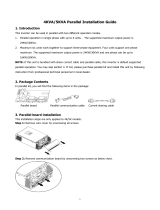
4.1 Overview of controls and displays
Figure 4.1: Overview of the Powador
Key
1 Display
Used to display measured values and confi guration
parameters
2 LED indicators
Used to display the operating state
3 Control keys
Used to switch between display and confi guration of
parameters
4 Cable fi ttings for AC connection
5 Night start-up key
Used to activate the displays after nightfall
6 Manual DC disconnect
Used to disconnect the inverter from the PV generator
7 RS232 interface
8 Plug connections and cable feedthroughs for
DC connection
3.3 Service
We place special emphasis on the quality and longevity of our
inverters, starting with the product development phase. More
than 60 years of experience in the fi eld of power converters
support us in this philosophy.
However, despite all quality assurance measures, faults may
occur in rare cases. In such cases, KACO new energy GmbH
will provide you with the maximum possible support. KACO
new energy GmbH will make every effort to remedy such
faults in an expeditious manner and without a great deal of
bureaucracy. In such a case, contact our service department
directly.
Telephone: +49(0)7132-3818-660
Section 3 · Notes on Installation and Operation
Section 4 · Operation
CAUTION
Incorrect use is prohibited.
123
4
7
6
5
8

Operating Instructions Powador 3200 / 4400 / 5300 / 5500 / 6600_EN Page 7
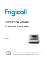
4.2 LED indicators
The inverter is equipped with three LEDs that provide informa-
tion about the various operating states as follows:
Figure 4.2: LED indicators
LED (1) (green):
The LED begins to light up as soon as the minimum voltage of
a photovoltaic module has been reached and goes out again
when the module voltage has fallen below this value.
The LED signals that the inverter is in standby mode. The inverter
is ready for operation.
LED (2) (green):
The LED always lights up when the inverter is feeding into the
grid.
LED (3) (red):
The LED displays when feed-in has been interrupted due to a
fault or when the potential-free contact is connected in ”Relay
33” mode.
Wait approximately 10 minutes to see if the fault is only tem-
porary in nature. If this is not the case, notify your authorised
electrician.
Check whether the fault in question relates to a general power
failure or whether the fuse between the counter and the
inverter has blown. If the fuse has blown, notify your autho-
rised technician. If there was a power failure, simply wait until
the fault has been cleared. The system automatically restarts.
4.3 Keys ”1” and ”2”
Figure 4.3: Powador control buttons
Key “1” is used to switch between the various displays for
measured values and data. Key“2” can be used to confi gure
settings. Here, menu navigation is divided into two levels. In
level 1 (display mode), measured values such as the PV array
voltage can be read. Here, only key“1” is activated. In level 2
(confi guration mode), key“1” is also used to navigate through
the individual displays. Settings, such as interface selection,
are confi gured with key“2”.
Section 4 · Operation
1
2
3
!
ok
IMPORTANT
If the feed-in phase fails (power failure on the public
grid), LED (3) does not light up. If this happens, all LEDs
and the display go out. The inverter is shut down com-
pletely.
The inverter can only resume its normal operation when
the feed-in phase is available once again.
ACTION
By pressing key “1” you can choose which measured
value is to be displayed.
The menus are continuous, which means that when you
arrive at the last entry in a menu, the fi rst entry is dis-
played once again the next time key“1” is pressed (see
fi gure 4.4).
IMPORTANT
The potential-free contact can also be used in ”Relay 33”
mode (section 4.4). In this case, LED (3) is not used to
indicate faults. If the contact is connected in ”Relay 33”
mode, LED (3) illuminates to indicate this status. The LED
(3) remains lit as long as the contact is connected.
If the inverter then experiences an error, it is not indi-
cated by the LED (3). Instead, it only appears as an error
message on the display.

Page 8 Operating Instructions Powador 3200 / 4400 / 5300 / 5500 / 6600_EN
4.4 Relay 33
The new version of the German Renewable Energies Act (EEG),
which took effect on 1 January 2009, now includes compen-
sation for personal consumption of self-generated PV energy
(§33). This applies to systems up to a maximum of 30kW.
The energy that is provided by the PV system can be directly
put to use by the appliances that are connected in your home.
In order to reap the benefi ts of this function, it is a good idea
to operate large appliances (e.g. washing machines, air condi-
tioning units, clothes dryers, dishwashers, etc.) when the
required amount of PV energy is available.
Activation
Before you can use the ”Relay 33” function, you have to enter
a special activation code on the device. This can be obtained
from your specialist dealer.
The ”Relay 33” function is now active.
You can use the menu item ”Relay 33 active yes/no” to switch
between the fault signal relay function and the ”Relay 33”
function at any time.
You will not have to enter the activation code for the next
activation.
Additional menu items are now available in menu level
2 (section 4.6). These menu items enable you to change the
AC switch-on threshold and the relay switch-on time.
Setting the parameters
In ”Relay 33” mode, the potential-free contact is connected
when the AC power is constantly above the set AC switch-on
threshold for a period of 30minutes. The AC switch-on thresh-
old can be adjusted in increments of 250W, up to the maxi-
mum AC power of the inverter in question. When delivered,
the AC switch-on threshold is set to 250W.
The relay switch-on time refers to the period of time that the
potential-free contact remains connected after it has been
switched on. This time can be adjusted in increments of one
hour, from one hour to a maximum of 10hours.
When delivered, the relay switch-on time is set to one hour.
After it has been switched on, the remaining time for the relay
is displayed under the menu item ”Remaining relay time” in
menu level 1. As long as the potential-free contact is con-
nected, LED (3) remains illuminated to indicate this status.
After the remaining relay time has elapsed, the contact is dis-
connected and the red LED goes out. To reconnect it, the set
switching conditions (AC switch-on threshold exceeded con-
stantly for a period of 30minutes) have to be met again.
NOTICE
When delivered, the ”Relay33” function is not active.
You have to order the function separately from your spe-
cialist dealer. It can be activated on the device after pay-
ment has been received.
ACTION
Activation is performed using the display and the control
keys.
–Press keys“1” and ”2” simultaneously to access menu
level 2.
–Use key“1” to access the menu item ”Relay 33 active
yes/no”.
–You can activate the function by selecting ”yes” with
key ”2”.
–When you then press key “1”, you reach the input
screen for the activation code, ”Please enter code
xxxx”.
–This is where you enter the activation code that you
obtained after your payment was received.
–Use key ”1” to select the digit positions (1-4).
–Use key ”2” to enter. Press key“2” to select the correct
value to be entered (0-9, A-F).
–Press key ”1” to confi rm.
ACTION
You set the AC switch-on threshold in menu level 2 (sec-
tion 4.6).
–Press keys“1” and ”2” simultaneously to access menu
level 2.
–Use key “1” to access the menu item
“Relay 33 from”.
–Use key“2” to set the desired AC switch-on threshold in
increments of 250 W, up to the maximum AC
power of the inverter.
ACTION
You set the relay switch-on time in menu level 2.
–Press keys“1” and ”2” simultaneously to access menu
level 2.
–Use key“1” to access the menu item ”Relay switch-on
time”.
–Use key“2” to select the desired relay switch-on time in
increments of 1hour from a range of 1 to 10hours.
Section 4 · Operation

Operating Instructions Powador 3200 / 4400 / 5300 / 5500 / 6600_EN Page 9
4.5 Level 1 menu – Display mode
The display menu is shown once the Powador inverter starts
up. Measured values and all of the counters are displayed
here. Key ”1” is used to navigate through the individual menu
items.
Inverter type display
Generator voltage and current
Grid voltage, current and power
External limit
Daily peak capacity
Relay 33 remaining time
Temperature inside unit
Yield counter
Yield today
Total yield
(Total) economy of CO2
Oper. hours cntr
Operating hours today
Total operating hours
Figure 4.4: Display mode menu
Explanation of the individual menu items:
Inverter type display
Display of the inverter type
Powador 3200 / 4400 / 5300 / 5500 / 6600
Generator voltage and current
The current voltage and current of the PV array that is con-
nected to the inverter.
Grid voltage, current and power
The current grid voltage, grid current and the power that is
currently being fed into the grid.
External limit
Power regulation according to the specifi cations of the
German Renewable Energies Act (EEG) to 60%, 30% or 0%.
Daily peak capacity
The peak power of the day in question that was fed into the
grid for a short time.
Relay 33 remaining time
Displays the remaining time for the Relay 33 function. This is
displayed only when the ”Relay 33” function is activated and
the potential-free contact is connected in ”Relay 33” mode.
The display format is hh:mm.
Temperature inside unit
Displays the current heat sink temperature in °C. The unit
switches off if it becomes too hot.
Yield counter
This counter totals all yields until it is reset again. The cus-
tomer can confi gure the time periods for this counter, e.g. as a
monthly counter. The counter can be cleared in the ”Clear
yield” confi guration mode.
Yield today
The power that has been fed into the grid during the current
day.
Total yield
The power that has been fed into the grid since start-up of the
inverter. The initial value can be set in the confi guration mode.
(Total) economy of CO2
Shows the CO2 savings of this PV system compared to the
German electricity mix. The CO2 savings are calculated from
the total yield and can also be cleared with this counter
(1kWh corresponds to 0.56kg of CO2 savings).
Oper. hours cntr
This counter totals all yields until it is reset again. The cus-
tomer can confi gure the time periods for this counter, e.g. as a
monthly counter. It can be cleared in the ”Clear yield” confi gu-
ration mode.
Operating hours today
Today’s hours of operation. As soon as the inverter is in
standby mode (i.e. when LED (1) lights up), the running time is
added up.
Total operating hours
The hours of operation since start-up of the inverter. As soon
as the inverter is in standby mode (i.e. when LED (1) lights up),
the running time is added up.
In addition, all status messages are integrated into this level:
As long as they are present, they are a part of the menu,
which means that they appear again after you have scrolled
completely through level 1. They are automatically
• cleared when the DSP (Digital Signal Processor) shows a
fault-free status, or
• replaced when the DSP transmits a status that results in
another message.
They appear only in level 1. If they occur while the menu
system is in another level, they are saved and displayed when
you have returned to level 1 as long as they are still present.
Section 4 · Operation

Page 10 Operating Instructions Powador 3200 / 4400 / 5300 / 5500 / 6600_EN
4.6 Level 2 menu – Confi guration mode
Software version
Confi guration version
Serial no.
Current country
Language selection
Clearing the feed-in meter
Defi ne total yield? (yes/no)
Defi ne total yield, if (yes) was previously selected
Select interface (RS232/RS485)
Settings for the RS485 address
S0 interface
Activate Relay 33
- Relay 33 activation prompt (yes/no)
- Password prompt
Defi ne switch-on power for Relay 33
Defi ne relay switch-on time for Relay 33
Activate power boost
Quick start
Figure 4.5: Confi guration mode menu
Explanation of the individual menu items:
Software version
The current software version is displayed here.
Confi guration version
The confi guration version is displayed here.
Serial no.
Display of the serial number specifi c to the unit.
Current country
Display of the current country settings.
Language selection
The language of the confi guration interface can be selected
here.
Clearing the feed-in meter
When the feed-in meter is cleared, all counters (“Counter
yield” and ”Counter oper. hours”) are reset to zero. To clear
the counters, select ”Yes” with key “2”, and confi rm your
selection by pressing the ”1”key. The required code is ”2”,
and is entered using key “2”. After confi rming again with
key“1”, all counters are cleared. ”Feed-in meter cleared!” is
shown to confi rm that the counters have been cleared.
“Counter yield” and ”Counter oper. hours” can be cleared sepa-
rately from the other counters. These counters are cleared in the
confi guration menu using key ”2” and the code ”2”. ”Counter
yield” and ”Counter oper. hours” are always cleared together.
Set total yield
Choose whether the total yield should be defi ned (yes/no).
Set total yield
Specify the counter reading for the total yield so that the coun-
ter does not begin at zero after start-up.
Interface selection
Key ”2” is used to switch between interfaces RS232 and
RS485.
Choice of interface and address setting
Using the ”Select interface” menu item, you can use key ”2”
to switch between the RS232 and RS485 interfaces.
If the RS485 interface is activated, you can reach the address
setting by pressing key ”1”. By pressing key“2”, the address
can be set in a consecutive manner from 1 to 32. The address
then returns to 1.
The RS485 interface is used to communicate with the Powa-
dor-proLOG. If several inverters are connected to a Powador-
proLOG, each address may only be used once. This makes it
possible to monitor 32 Powador inverters with one Powador-
proLOG.
To connect the RS485 interface, please contact your installer.
S0 interface pulse rate
The S0 interface is designed as a galvanically isolated transis-
tor output. This interface is designed according to DIN
EN 62053-31:1999-04 (Pulse output devices for electrome-
chanical and electronic meters).
The S0 interface pulse rate can be chosen in three unit inter-
vals: 500, 1,000 and 2,000 pulses/kWh.
To connect the S0 interface, please contact your installer.
Section 4 · Operation
ACTION
To access the confi guration mode, press both keys at the
same time. The software version is displayed. Pressing
key ”1” now switches to the next menu item. Changes
can be made in the respective menu item by pressing key
”2”. The setting value increases each time key ”2” is
pressed. If the maximum value has been reached, the
value returns to the minimum setting option.

Operating Instructions Powador 3200 / 4400 / 5300 / 5500 / 6600_EN Page 11
Relay 33 active yes/no
You can use this menu item to switch the potential-free con-
tact between the ”Relay 33” mode and the fault signal relay
mode (see Installation Instructions for Authorised Electricians,
section 5, Installation and Start-Up).
Entering the activation code for Relay 33
You have to enter an activation code when you activate the
”Relay 33” function for the fi rst time. You only have to enter
this code for the fi rst activation. Once the function has been
activated, you can activate and deactivate it without having to
re-enter the activation code.
Switch-power for Relay 33
This menu item is only displayed when the potential-free con-
tact is switched to ”Relay 33” mode. You can use this menu
item to set the minimum switch-on power that must be pres-
ent for 30minutes so that the contact connects (see Installa-
tion Instructions for Authorised Electricians, section 5, Instal-
lation and Start-Up).
Relay switch-on time for Relay 33
This menu item is only displayed when the potential-free con-
tact is switched to ”Relay 33” mode. Use this menu item to set
how long the contact will remain active after connecting (see
Installation Instructions for Authorised Electricians, section 5,
Installation and Start-Up).
Power Boost
Power Boost mode can be activated by pressing key ”2”
twice. This changes the frequency of IGBT bridge from 17kHz
to 9kHz. When this change occurs, note that 9kHz is within
the range of audible frequencies.
The Power Boost mode improves the degree of effi ciency and
can be used where the operating noise from the inverter is
acceptable.
Quick start
The inverter can also be started up without any waiting period
for the purpose of testing or for the purpose of acceptance by
your power supply company.
If the inverter is already feeding into the grid, this menu item
is not available.
If there is insuffi cient PV array power, the inverter stops feed-
ing into the grid after a short period of time.
4.7 DC disconnect
The inverters include an internal DC disconnect, which allows
for the inverter to be disconnected from the photovoltaic gen-
erator in case of repair or fault.
To disconnect the inverter from the photovoltaic generator,
turn the internal DC disconnect on the underside of the
inverter from the ON (1) position to the OFF (0) position (see
fi gure 4.1).
When delivered, the inverter’s internal DC disconnect is in the
OFF (0) position.
4.8 Night start-up key
The unit switches off in the evening as nightfall approaches.
At this point, nothing is shown on the display. In order to
retrieve the values from the current day (daily yield, daily hours
of operation and max. feed-in power) after the display
switches off, the unit can also be activated during the night by
pressing the night start-up key on the underside of the
inverter.
You can now scroll through the menu and retrieve the saved
values. If over one minute elapses without a key being pressed,
the unit switches off automatically once again.
The ”Counter oper. hours ”, ”Total operating hours”, ”Counter
yield” and ”Total yield” data are permanently saved and
totalled. This data is not lost even if the inverter is switched off
for a long time. The daily yield, daily hours of operation and
the max. daily feed-in power are available until the following
morning and are cleared when PV generator voltage is present
again.
ACTION
To do this, press the night start-up key (see fi gure 4.1 -
(5)) on the underside of the unit for approximately 5 sec-
onds until a display appears.
Section 4 · Operation
ACTION
Settings are saved only upon exiting confi guration
mode. If two minutes elapse without a button being
pressed, confi guration mode is exited automatically. Con-
fi guration mode can also be exited immediately by pressing
both keys. As a confi rmation, ”Settings saved” appears on
the display. The settings are now permanently saved in the
Powador inverter.
ACTION
Keep key “2” pressed down for a short time until the
inverter switches on (relays switch audibly) and the green
feed-in LED (2) lights up. If there is insuffi cient PV array
power, the inverter stops feeding into the grid after a short
period of time.
IMPORTANT
In normal mode, the switch must be switched on. If not,
power cannot be fed into the grid.

Page 12 Operating Instructions Powador 3200 / 4400 / 5300 / 5500 / 6600_EN
4.9 The serial RS232 interface
Operating data can be transmitted to a computer (e.g. note-
book) over a galvanically isolated serial interface (see fi gure
4.1 - (6)) from where it can then be individually processed fur-
ther using standard spreadsheet software.
A standard serial 1:1 interface cable is all that is required for
connecting the inverter to the computer. The cable length
should not exceed 20 metres.
The data from the inverter is sent unidirectionally as pure
ASCII text over the serial interface. The data is not checked for
errors.
The RS232 interface has the following parameters:
Baud rate Data bits Parity Stop bits Protocol
9600 baud 8 None 1 None
Figure 4.6 shows, as an example, a few of lines of transmis-
sion via the RS232 interface.
The interface of the connected PC or laptop must comply with
the standard for RS232 interfaces. Some computer manufac-
turers do not fully adhere to the standard. In such cases, prob-
lems may occur during data transmission.
Data can be received with any terminal emulator, which comes
with every operating system, or with the KACO-viso visualisa-
tion tool.
Together with the Powador inverter, KACO-viso takes over the
role of a data logger. It saves the data from the inverter and
displays it in various diagram types as a daily or monthly rep-
resentation.
The PC, however, must also run continuously. Because of the
amount of energy used, this type of monitoring only makes
sense over limited periods, such as during a fault analysis. For
permanent monitoring, we recommend the optional accesso-
ries (see section 5).
NOTICE
The KACO-viso visualisation software can be down-
loaded from
http://www.kaco-newenergy.de
NOTICE
Calculating effi ciency by measuring the current and volt-
age values leads to unusable results due to the tolerances
of the measuring units.
The sole purpose of these values is to monitor the basic
operation of the system.
Spalte 1 2 3 4 5 6 7 8 9 10
00.00.0000 00:05:30 4 363.8 0.37 134 226.1 0.53 103 23
00.00.0000 00:05:40 4 366.0 0.39 142 226.1 0.53 112 23
00.00.0000 00:05:50 4 359.5 0.41 147 226.1 0.53 116 23
00.00.0000 00:06:00 4 369.8 0.42 155 226.1 0.58 118 23
00.00.0000 00:06:10 4 377.0 0.43 162 226.1 0.63 131 23
00.00.0000 00:06:20 4 373.6 0.45 168 226.1 0.63 133 23
00.00.0000 00:06:30 4 364.0 0.48 174 226.1 0.68 146 23
00.00.0000 00:06:40 4 364.3 0.49 178 226.1 0.68 146 23
Column Meaning Column Meaning
1 Placeholder 6 Generator power in W
2 Daily running time 7 Line voltage in V
3 Operating state (table 4.2) 8 Line current, feed-in current in A
4 Generator voltage in V 9 Power fed into the grid in W
5 Generator current in A 10 Temperature of the unit in °C
Table 4.1: Explanation of the individual columns of the log
5
5
5
5
5
5
5
5
Section 4 · Operation
Column 1

Operating Instructions Powador 3200 / 4400 / 5300 / 5500 / 6600_EN Page 13
4.10 The RS485 interface
Powador inverters are also equipped with an RS485 interface
in order to enable remote monitoring of your photovoltaic
system. Several inverters can be monitored over this interface
at the same time. Using the Powador-proLOG series, you can
receive yield and operating data as well as error messages by
SMS (text message) or e-mail. This monitoring option is espe-
cially recommended for situations where you are unable to
check the functionality of the system on-site at regular inter-
vals, e.g. if you live far away from the system site. In addition,
you can use the Powador-link within your system to bridge
long distances between several inverters or between an
inverter and the Powador-proLOG using wireless radio trans-
mission. Contact your installer if you wish to add remote mon-
itoring to your system.
4.11 External limiting
As of 01/01/2009, the German Renewable Energies Act (EEG)
requires power regulation for systems larger than 100kW. In
principle, each individual unit in a network with other units
can become a system of this size. Therefore, each inverter
must have an option for reducing power, even if this is not
needed in a system that is smaller than 100kW.
KACO uses a ripple control receiver to implement this power
reduction. The power supply company can use this unit to
reduce the system’s power via the Powador-proLOG XL, as
necessary. For this, the following levels are possible: 0 %,
30 %, 60 % or 100 % of AC power. With a setting of 30 % or
60%, the inverter limits the power to 30 % or 60 %. With a
setting of 0 %, the inverter disconnects from the grid. Normal
feed-in mode occurs at 100 %.
When the power supply company requests a reduction in the
power, the Powador-proLOG receives the corresponding
signal via the ripple control receiver. The Powador-proLOG
then forwards the information to all connected inverters,
which reduce power as prescribed by the power supply com-
pany. After a specifi ed period of time without any signal from
the power supply company, the inverters return to normal
operation.
For the duration of the power reduction, the display shows the
power reduction with a corresponding message (e.g. ”Exter-
nal limit xxx%”) and the LED (2) fl ashes once a second. You
can still use the other display functions as usual during a
power reduction.
The ripple control receiver is connected to the Powador-pro-
LOG XL, which is mandatory for the use of power limitation
(power control). You do not have to make any changes to the
inverter in order to use power limitation, since it is integrated
in the inverter as standard. It is activated via the Powador-
proLOG XL.
A group of up to a total of 32 inverters can be symmetrised in
this way. All inverters of a group must be assigned a unique
SYM bus address within the range of 1 to 32. In addition, the
feed-in phase and the maximum asymmetry for any inverter
must be set so that the correct symmetrisation can result.
4.12 Display
Inverters in the Powador series are equipped with a back-lit
LCD (see fi gure 4.1 - (1)) that displays measured values and
data.
In normal mode, the backlight is switched off. As soon as you
press one of the buttons, the backlight is activated. If no key
is pressed after about one minute, it switches off once again.
Section 4 · Operation
IMPORTANT
Due to measuring tolerances, the measured values may
not always correspond to the actual values. The measur-
ing elements on the inverter have been selected to ensure
maximum solar yields.
Due to these tolerances, the daily yields displayed on the
inverter may deviate from the values on your supply grid
operator's feed-in meter by up to 15 %.
NOTICE
Calculating effi ciency by measuring the current and volt-
age values leads to unusable results due to the tolerances
of the measuring units.
The sole purpose of these values is to monitor the basic
operation of the system.

Page 14 Operating Instructions Powador 3200 / 4400 / 5300 / 5500 / 6600_EN
Status Explanation Comment
0 Inverter has just switched on Only for a brief period after being fi rst switched on in the morning.
1 Waiting to start Grid parameters and generator voltage are being checked.
2 Waiting to switch off Insuffi cient generator voltage and generator power. The status before it
switches over to night shutdown mode.
3 Constant volt. control The inverter continues to operate with minimum MPP voltage when the
feed-in power is low.
4 Feed-in mode The inverter is feeding into the grid.
8 Self test The line relay and the shutdown of the power electronics are tested
prior to the commencement of feed-in mode.
9 Test mode For internal operation only.
11 Power limitation If the generator is producing too much power, the inverter limits itself to
the maximum power. This can occur in the midday hours if the genera-
tor has been too largely dimensioned. This is not a malfunction.
60 PV voltage too high
for feed-in
The inverter can only begin feeding into the grid once the PV voltage
falls below a specifi ed value.
61 Power Control Power Control was activated by the grid operator. The inverter limits its
power.
62 Standalone mode The inverter was switched to standalone mode by the Powador Grid-
Save. The inverter is disconnected from the public low-voltage grid.
63 P(f) frequency-dependent power
reduction
Frequency-dependent power reduction is activated with the activation
of the BDEW Medium Voltage Directive (“Mittelspannungsrichtlinie”).
Power reduction starts at 50.2Hz.
64 Output current limiting The AC current is limited once the specifi ed maximum value has been
reached.
Table 4.2: Explanation of the operating states
Fault messages
When these error messages are displayed, the feed-in is interrupted, the red LED (3) lights up and the fault signal relay is switched. This
error correction takes a country-specifi c length of time. Afterwards, the red fault LED (3) goes out, the fault signal relay drops out again,
and the display signals that it is ready to feed into the grid once again. Once the fault is gone, the Powador inverter feeds into the
grid again after a country-specifi c time period. Many of these fault signals point to a fault in the grid, and are, therefore, not an opera-
tional fault on the part of the Powador inverter. The minimum triggering levels are determined by applicable standards (e.g. VDE0126-1-1),
and the inverter must switch off if the permitted values are exceeded.
When the Relay 33 function is activated, LED (3) is not used to indicate faults. If the contact is connected in ”Relay 33” mode, LED (3)
illuminates to indicate this status. The LED remains lit as long as the contact is connected.
If the inverter then experiences an error, it is not indicated by the LED (3). Instead, it only appears as an error message on the display.
Section 4 · Operation
Operating states
For the status, consult the data that is logged via the RS485 interface.

Operating Instructions Powador 3200 / 4400 / 5300 / 5500 / 6600_EN Page 15
Section 4 · Operation
Status Display Explanation
10 Temperature inside
high in unit
If the inverter overheats due to a lack of air circulation, the inverter switches off.
This can occur if the ambient temperature is too high, the cooling fi ns are covered
or the inverter is defective.
18 Error current
switch-off
The residual current is too high. The integrated AC/DC-sensitive residual current
circuit breaker registered an impermissibly high leakage current going to PE.
19 Generator insulation fault Insulation resistance from PV-/PV+ to PE is too low.
30 Error
Measurement
The current and voltage measurements in the inverter are not plausible. This can be
caused by very dynamic weather conditions if quick changes between low feed-in
power and high feed-in power occur.
31 RCD module error An error has occurred in the AC/DC-sensitive residual current circuit breaker.
32 Fault
Self test
The internal grid separation relay test has failed. If this internal error occurs several
times, notify your authorised electrician.
33 Fault
DC feed-in
The DC feed-in has exceeded the permitted value. This DC feed-in can be impressed
from the grid on the Powador inverter so that no inverter fault exists. If this error
occurs several times, notify your authorised electrician.
34 Fault
Communication
A communication error has occurred in the internal data transmission. Notify your
authorised electrician to check the data cable.
35 Protection shutdown (SW) Protection shutdown of the software (AC overvoltage, AC overcurrent, DC link
overvoltage). This is not an error, but instead a grid-related shutdown.
36 Protection shutdown (HW) Protection shutdown of the hardware (AC overvoltage, AC overcurrent, DC link
overvoltage). This is not an error, but instead a grid-related shutdown.
38 Fault
PV overvoltage
The voltage of the PV generator is too high. The PV array is incorrectly dimen-
sioned. Notify your authorised electrician.
41 Line failure
Undervoltage L1
The voltage of a grid phase L1 is too low, the grid cannot be fed into.
42 Line failure
Overvoltage L1
The voltage of a grid phase L1 is too high, the grid cannot be fed into.
43 Line failure
Undervoltage L2
The voltage of grid phase L2 is too low, the grid cannot be fed into (only for
active 3-phase monitoring).
44 Line failure
Overvoltage L2
The voltage of grid phase L2 is too high, the grid cannot be fed into (only for
active 3-phase monitoring).
45 Line failure
Undervoltage L3
The voltage of grid phase L3 is too low, the grid cannot be fed into (only for
active 3-phase monitoring).
46 Line failure
Overvoltage L3
The voltage of grid phase L3 is too high, the grid cannot be fed into (only for
active 3-phase monitoring).
47 Line failure
line-to-line voltage
The phase angle between the individual phases and the three-phase supply
network is not correct (only for active 3-phase monitoring).
48 Line failure: underfreq. The line frequency is too low. This error can be grid-related.
49 Line failure: overfreq. The line frequency is too high. This error can be grid-related.
50 Line failure
Average voltage
The grid voltage measurement according to EN 50160 has exceeded the maxi-
mum permitted limit value. This error can be grid-related.
57 Waiting for
reconnect
After a fault, the inverter waits a defi ned country-specifi c time period before it
can switch back on.
58 Overtemperature
Control board
The temperature inside the unit was too high. The inverter switches off to prevent
damage to the hardware. Provide suffi cient ventilation.
59 Self test error An error occurred during the buffer inspection.
Error (EEPROM)
no parameters
An error occurred in the EEPROM.
ERROR no parameters An error with no parameters.
Table 4.3: Fault messages

Page 16 Operating Instructions Powador 3200 / 4400 / 5300 / 5500 / 6600_EN
Section 5 · Troubleshooting
5 Troubleshooting
In line with our continuously expanding quality assurance system, we endeavour to eliminate all errors and faults. You have purchased a
product which left our factory in proper condition. Each individual unit has successfully passed an endurance test as well as extensive
tests for the purpose of assessing the operating behaviour and the protective equipment.
If your photovoltaic system does not function properly despite these measures, we suggest the following troubleshooting procedures:
The fi rst step is to check that the PV array and grid connections are properly connected to the Powador. In doing so, observe all the safety
instructions specifi ed in this manual. Monitor the inverter closely and, where applicable, make a note of the displays and LEDs.
The following faults may occur and should be remedied as described.
Fault Cause of fault Remedy/explanation
Inverter displays an
impossible daily peak
value.
Faults in the grid voltage. The inverter continues to operate as normal without losses to
the yield, even when an erroneous daily peak value is displayed.
The value is reset overnight. To immediately reset the value, the
inverter must be switched off and switched on again by discon-
necting it from the grid and switching off the DC.
Daily energy yields do
not correspond with the
yields on the energy
supply company’s
feed-in meter.
Tolerances of the measur-
ing elements in the inverter
The measuring elements on the inverter have been selected to
ensure maximum solar yields. Due to these tolerances, the daily
yields displayed on the inverter may deviate from the values on
your supply grid operator’s feed-in meter by up to 15%.
The display is blank and
the LEDs do not light up.
–The unit is in night
shutdown mode.
–There is no grid voltage.
–The PV array voltage is
too low.
The inverter switches to night shutdown mode as soon as the
PV array voltage is below the minimum feed-in voltage for a
longer period of time. In this case, the display will also switch
off. In order to still be able to view the currently measured
values, you can switch on the inverter via the night start-up key.
A grid failure will also cause the display to go blank and feed-in
to stop. Wait until the public low-voltage grid is available again.
If the display does not light up during normal daytime hours,
please contact your solar installer.
The inverter is active but
does not feed into the
grid.
–Insuffi cient generator
voltage available
–The line voltage or the
PV array voltage is not
stable.
After sunrise, at sunset and when there is not enough solar
insolation due to bad weather conditions or due to the solar
modules being covered with snow, the generator voltage or the
generator power that comes from the roof may be too low to
be able to feed in.
Before the feed-in process begins, the inverter has to check the
line parameters for a certain period of time. The length of time
it takes to switch back on again differs by country according to
applicable standards and regulations and can take several min-
utes.
The inverter is active but
does not feed into the
grid. The insolation is
suffi cient.
The inverter has inter-
rupted the feed-in due to
a fault.
After a feed-in interruption due to a fault (line failure, overtem-
perature, overload, etc.), the inverter checks the line parame-
ters for a certain period of time. The length of time it takes to
switch back on again differs by country according to applicable
standards and regulations and can take several minutes.
Interruptions can occur during the day when the grids are
faulty. Notify your solar installer if the inverter shuts down reg-
ularly over a period of several weeks (more than 10 times per
day).
For an explanation of the individual display error texts, please
see the fault signals.

Operating Instructions Powador 3200 / 4400 / 5300 / 5500 / 6600_EN Page 17
Fault Cause of fault Remedy/explanation
The inverter stops
supplying power to the
grid shortly after being
switched on, even
though there is suffi -
cient sunlight.
Faulty grid separation relay
in the inverter.
Although there is suffi cient sunlight, the inverter feeds into the
grid only for a few seconds before switching off again. During
the short feed-in period, the inverter shows that the power
being fed into the grid is between 0 and 5W. If the inverter is
defi nitely receiving suffi cient generator power, the grid separa-
tion relay is presumably faulty, thus preventing the inverter
from connecting. Please contact your solar installer.
The line fuse trips. –The line fuse capacity is
too low.
–Damage to the inverter’s
hardware.
In cases of high insolation, the inverter can – depending on the
PV array – exceed its rated current for a short period. For this
reason, the capacity of the inverter’s pre-fuse should be some-
what higher than the maximum feed-in current.
If the line fuse immediately trips when the inverter switches to
feed-in mode (after the start-up period is complete), the invert-
er’s hardware is probably damaged. Contact your solar installer.
Noise emission from the
inverter.
Particular ambient
conditions
Power Boost mode is
activated.
When there are certain ambient conditions, the units may emit
audible noises. The following causes may be determining fac-
tors in this regard:
–Line interference or line failure caused by particular loads
(motors, machines, etc.) which are either connected to the
same point on the grid or located in the vicinity of the
inverter.
–In cases of dynamic weather conditions (frequent switching
between sunny and cloudy conditions) or strong insolation,
a light hum may be audible due to the increased power.
–With particular grid conditions, resonances may form between
the unit’s input fi lter and the grid, which may be audible even
when the inverter is switched off.
–People with very sensitive hearing (particularly children) may be
able to hear the high-frequency hum caused by the inverter’s
operating frequency of approximately 17kHz.
Such noise emissions do not affect the operation of the inverter.
Nor can they lead to loss of effi ciency, failure, damage or to a
shortening of the unit’s service life.
When Power Boost mode is activated, noise emission is normal.
The Power Boost mode should be activated only in environ-
ments where the operating noise is acceptable.
In spite of high insola-
tion, the inverter does
not feed in the maxi-
mum power into the
low-voltage grid.
The device is too hot and
the power is reduced.
The temperature inside the unit became too high. The inverter
reduced the power to prevent damage to the unit. Starting
from an internal temperature of 75°C, the inverter limits the
power and levels off between 75°C and 80°C. An internal tem-
perature of 85°C is only reached if convection cooling is
impeded by external factors, e.g. by covering the cooling fi ns.
Provide for suffi cient cooling of the unit.
Additional devices that
are connected via the
potential-free contact
suddenly start up, even
though the ”Relay 33”
function is deactivated
and the inverter indicates
an error.
The potential-free contact
connects to indicate an
error.
If the ”Relay 33” function is not activated, the potential-free
contact functions as a fault signal relay and therefore indicates
errors. However, if additional devices that are provided for the
”Relay 33” function are connected to the inverter via the con-
tact, they can still start up when the inverter experiences an
error, because the contact is connected at that point in time. If
you deactivate the ”Relay 33” function, we recommend that
you disconnect devices from the inverter that were connected
for this function.
Table 5.1: Troubleshooting
Section 5 · Troubleshooting

Page 18 Operating Instructions Powador 3200 / 4400 / 5300 / 5500 / 6600_EN
Section 5 · Troubleshooting
Section 6 · Recycling and Disposal
If the measures described in this guide do not assist in clearing
the fault, please notify your installer.
In order for our factory customer service department to
respond in an appropriate and expeditious manner, some
details are necessary:
Inverter details
– Unit serial number
– Model
– A short description of the error
– Is the error reproducible? If yes, how?
– Does the error occur sporadically?
– Describe the prevailing insolation conditions when the
error occurred.
– Time
Details pertaining to the photovoltaic module
– Module type, manufacturer (if available,
send data sheet)
– The number of modules in series
– The number of strings
– Generator power
6 Recycling and Disposal
For the most part, both the inverter and the corresponding
transport packaging are made from recyclable raw materials.
Unit
Do not dispose of faulty inverters or accessories together with
household waste. Ensure that the old unit and any accessories
are disposed of in a proper manner.
Packaging
Ensure that the transport packaging is disposed of properly.

Installation instructions Powador 3200 / 4400 / 5300 / 5500 / 6600_EN Page 3
For authorised electricians
Installation Instructions
Powador 3200 / 4400 / 5300 / 5500 / 6600
1 About this Documentation ..........................................4
1.1 Retention of documents ..............................................4
1.2 Symbols used in this document ...................................4
1.3 CE marking ................................................................4
1.4 Name plate ................................................................4
2 Safety Instructions and Regulations ...........................5
3 Technical Data ...........................................................6
4 Unit Description .........................................................8
4.1 Scope of delivery ........................................................8
4.2 Dimensioning the PV generator ...................................8
4.3 Protection concepts ....................................................9
5 Installation and Start-Up .............................................9
5.1 Selecting an appropriate place for installation .............9
5.2 Installing the inverter ................................................ 10
5.3 Electrical connection ................................................ 11
5.4 Interfaces ................................................................. 15
(A) Connecting the fault signal relay / relay 33 ................ 15
(B) Connecting the S0 output ......................................... 15
(C) Connecting the RS485 interface ............................... 15
5.5 Limiting during asymmetric feed-in ...........................16
5.6 SYM bus test ............................................................ 16
5.7 Power Boost ............................................................. 17
5.8 Grid monitoring ........................................................ 17
5.9 Starting up the inverter ............................................. 17
5.10 Programming parameters .........................................18
6 Switching the Inverter Off .........................................20
7 Powador as Part of a PV System ...............................21
7.1 System layout ........................................................... 21
7.2 System with multiple inverters ..................................23
8 Troubleshooting .......................................................25
9 Documents ..............................................................27
9.1 EU Declaration of Conformity .................................... 27
9.2 Certifi cate of compliance ..........................................28
9.3 Certifi cate of compliance ..........................................29

Page 4 Installation instructions Powador 3200 / 4400 / 5300 / 5500 / 6600_EN
ATTENTION
Failure to observe a warning indicated in this manner may
lead to damage to property.
NOTICE
Useful information and notes.
ACTION
This symbol indicates that a certain action is required.
IMPORTANT
Failure to observe this information may result in reduced
convenience or impaired functionality.
High voltage
Risk of fi re or explosion
Risk of burns
Disconnect before starting work
Read the manual
1.3 CE marking
The CE marking is used to document that the Powador inverter
shown on the name plate fulfi ls the fundamental requirements
of the following relevant directives:
– Directive relating to electromagnetic compatibility
(Council Directive 2004/108/EC)
– Low voltage directive
(Council Directive 2006/95/EC)
1.4 Name plate
The name plate showing the exact designation of the unit is
located on the support plate on the underside of the housing.
1 About this Documentation
The following notes guide you through the entire documenta-
tion. Additional documents are applicable in conjunction with
these operating and installation instructions.
We assume no liability for any damage caused by failure to
observe these instructions.
Other applicable documents
When installing the inverters, be sure to observe all assembly
and installation instructions for components and other parts of
the system. These instructions are delivered together with the
respective components and other parts of the system.
ATTENTION
Read the manual
We assume no liability for any damage caused by failure to
observe these instructions.
1.1 Retention of documents
Please pass these operating and installation instructions
on to the system operator. The system operator retains the
documents. The instructions must be available whenever they
are needed.
1.2 Symbols used in this document
When installing the inverter, observe the safety instructions
included in these installation instructions.
DANGER
Failure to observe a warning indicated in this man-
ner will lead directly to serious bodily injury or
death.
WARNING
Failure to observe a warning indicated in this man-
ner may lead directly to serious bodily injury or
death.
CAUTION
Failure to observe a warning indicated in this man-
ner may directly lead to minor or moderate bodily
injury.
Section 1 · About this Documentation

Installation instructions Powador 3200 / 4400 / 5300 / 5500 / 6600_EN Page 5
2 Safety Instructions
and Regulations
DANGER
Danger due to lethal voltages.
Lethal voltages are present within the unit and on
the power supply lines. Therefore, only authorised
electricians may install and open the unit.
Even when the unit is disconnected, high contact
voltages may still be present within the unit.
Standards and regulations
IEC 60364-7-712:2002:
Requirements for special systems or locations – Solar photo-
voltaic (PV) power supply systems.
Technical rules
The installation must be suited to the on-site conditions and
comply with local regulations and technical rules.
Accident prevention regulations
The inverter must be installed by an authorised, specialist
electrician who is approved by the supply grid operator. The
electrician is responsible for observing existing standards and
regulations.
The proper and safe operation of this unit requires proper
transportation, storage, assembly and installation, as well as
careful operation and maintenance.
Only authorised electricians who have read and fully understood
all of the safety instructions contained in these operating and
installation instructions, as well as other instructions concerning
assembly, operation and maintenance, may work on this unit.
When this unit is operating, it is unavoidable that certain parts
of the unit carry hazardous voltages, which can lead to death
or serious bodily injury. The precautions listed below must be
followed in order to minimise the risk of death or injury.
–
The unit must be installed in compliance with safety
regulations, as well as all other relevant national or local
regulations. To ensure operational safety, proper grounding,
conductor dimensioning and appropriate protection against
short circuits must be provided.
– Keep all covers on the unit closed during operation.
– Prior to performing any visual inspections or maintenance,
ensure that the power supply has been switched off and is
prevented from being inadvertently switched back on.
– Never touch the electrical connections when you have to
take measurements while the power supply is switched on.
– Remove all jewellery from your wrists and fi ngers.
– Make sure that the testing equipment is in good and safe
operating condition.
– When working on the unit while it is switched on, stand on
an insulated surface, ensuring that there is no grounding
connection.
– Follow the instructions contained in these operating and
installation instructions and observe all danger, warning
and safety information.
–
This list does not constitute a complete listing of all measures
required for the safe operation of the unit. Contact your
specialist dealer if any specifi c problems arise which are not
suffi ciently covered for the purposes of the buyer.
Modifi cations
It is generally not permitted to modify the inverter. Modifi cations
to the surroundings of the inverter are permitted only if they
comply with national standards.
CAUTION
Risk of damage due to improper modifi cations.
Never modify or manipulate the inverter or other
components of the system.
Information on the following topics can be found in
the Operating Instructions:
• Transportation
• Intended use
• Factory warranty and liability
• Service
Section 2 · Safety Instructions and Regulations
/