NXRTi USER’S MANUAL UNINTERRUPTIBLE POWER SUPPLY (UPS)
Xtreme Power Conversion Corporation (Rev 8/29/13) Page 2
Table of Contents
IMPORTANT SAFETY INSTRUCTIONS: ................................................. 4
INTRODUCTION ........................................................................................... 6
PRODUCT DESCRIPTION .......................................................................... 6
Double Conversion On-Line Technology ................................................................................................... 7
Functions and Characteristics ................................................................................................................... 8
SYSTEM CONFIGURATION ........................................................................ 9
LED Description ....................................................................................................................................... 10
LCD Descriptions ..................................................................................................................................... 11
RS-232 Standard Interface ...................................................................................................................... 13
SNMP Communications Option .............................................................................................................. 14
DETERMINING THE POWER REQUIREMENTS OF YOUR
EQUIPMENT ............................................................................................... 14
HARDWARE INSTALLATION GUIDE ................................................... 15
Safety Information .................................................................................................................................. 15
Storage and Transportation .................................................................................................................... 15
Environment ........................................................................................................................................... 15
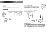
Installation .............................................................................................................................................. 16
19” Cabinet Ear Installation .................................................................................................................... 18
INITIAL CONNECTION AND STARTUP: .............................................. 19
USER’S OPERATIONS .............................................................................. 22
Turning Off the UPS when connected to an AC source .......................................................................... 23
Starting the UPS from a DC source (cold start) ....................................................................................... 23
Turning Off the UPS when in Utility Mode ............................................................................................. 23
Turning Off the UPS when in Battery Mode ........................................................................................... 23
Self Test & Mute Test Operation ............................................................................................................ 23
Parameter Setting ................................................................................................................................... 24
ECO mode setting................................................................................................................................ 24