Xtreme NXRTi 3000VA User manual

Category
Uninterruptible power supplies (UPSs)
Type
User manual

This manual is also suitable for

NXRTi Online UPS
1000VA, 2000VA, 3000VA Models
User & Installaon Manual
www.xpcc.com | © 2015 Xtreme Power Conversion Corporaon. All rights reserved. (Rev 6/23/15)
Xtreme Power Conversion Corporaon
NXRTi Users Manual
Page 2
Uninterrupble Power Supply
Table of Contents
Introducon.................................................................................................6
Product Descripon..................................................................................... 6
Double Conversion Online Technology............................................................................................6
Funcons and Characteriscs..........................................................................................................7
System Conguraon...................................................................................7
LED Descripon...............................................................................................................................9
LCD Descripons........................................................................................................................... 10
RS-232 Standard Interface.............................................................................................................12
SNMP Communicaons Opon.....................................................................................................12
Determining the Power Requirements of Your Equipment..........................12
Hardware Installaon Guide.......................................................................13
Safety Informaon.........................................................................................................................13
Storage and Transportaon...........................................................................................................13
Environment..................................................................................................................................13
Installaon.....................................................................................................................................14
19” Cabinet Ear Installaon...........................................................................................................16
Inial Connecon and Startup....................................................................18
Users Operaons...................................................................................... 20
Turning O the UPS When Connected to an AC Source................................................................20
Starng the UPS From a DC Source (Cold Start)............................................................................20
Turning O the UPS When in Ulity Mode....................................................................................20
Turning O the UPS When in Baery Mode..................................................................................20
Self Test & Mute Test Operaon....................................................................................................20
Parameter Seng..........................................................................................................................21
ECO Mode Seng..........................................................................................................................21
Bypass Output Seng...................................................................................................................22
Parameter Inquiring...................................................................................................................... 23
Run Mode..................................................................................................................................... 25
Xtreme Power Conversion Corporaon
NXRTi Users Manual
Page 3
Uninterrupble Power Supply
Maintenance..............................................................................................27
Baeries.....................................................................................................27
Replacing the Baery.....................................................................................................................27
Troubleshoong.........................................................................................27
LED Indicaon and Warning Table.................................................................................................28
Specicaons.............................................................................................30
Shipping List.............................................................................................. 30
Obtaining Service.......................................................................................31
Xtreme Power Conversion Limited Warranty..............................................32
Appendix A: Extended Baery Pack User Guide.........................................33
Esmated Run Time for UPS with Extended Baery Packs............................................................33
LED Descripon.............................................................................................................................35
Extended Baery Pack Operaon..................................................................................................35
Extended Baery Pack Installaon................................................................................................36
Extended Baery Pack Q & A........................................................................................................37
Xtreme Power Conversion Corporaon
NXRTi Users Manual
Page 4
Uninterrupble Power Supply
Thank you for selecng this uninterrupble power supply (UPS). It provides you with protecon for connected
equipment. Please read this manual before installing the NXRTi-Series UPS models NXRTi-1000, NXRTi-2000 and
NXRTi-3000 as it provides important informaon that should be followed during installaon and maintenance of
the UPS and baeries, allowing you to correctly set up your system for the maximum safety and performance. In-
cluded is informaon on customer support and service, if it is required. If you experience a problem with the UPS,
please refer to the Troubleshoong secon in this manual to correct the problem. If the problem is not corrected,
please collect informaon so that the Technical Support personnel can more eecvely assist you.
WARNING: Any changes or modicaons not expressly approved by the manufacturer of this device could void the
users authority to operate the equipment.
IMPORTANT SAFETY INSTRUCTIONS: (SAVE THESE INSTRUCTIONS)
CAUTION! (UPS having Internal Baeries): Risk of electrical shock – Hazardous live parts inside this unit are ener-
gized from the baery supply even when the input AC power is disconnected.
CAUTION! (No User serviceable Parts): Risk of electrical shock, do not remove cover. No user serviceable parts
inside. Refer servicing to qualied service personnel.
CAUTION! (Non-isolated Baery supply): Risk of electric shock, baery circuit is not isolated from AC input, haz-
ardous voltage may exist between baery terminals and ground. Test before touching.
WARNING! (Fuses): To reduce the risk of re, replace only with the same type and size of fuse.
WARNING! Unit intended for installaon in a controlled environment.
CAUTION! Do not dispose of baeries in a re, the baery may explode.
CAUTION! Do not open or mulate the baery, released electrolyte is harmful to the skin and eyes.
CAUTION! A baery can present a risk of electric shock and high short circuit current. The following precauon
should be observed when working on baeries:
Remove watches, rings or other metal objects.
Use tools with insulated handles.
To reduce the risk of electric shock, disconnect the UPS from the main supply before installing a computer inter-
face signal cable. Reconnect the power cord only aer signaling interconnecons have been made.
Servicing of baeries should be performed or supervised by personnel with knowledge of baeries and the re-
quired precauons. Keep unauthorized personnel away from baeries.
These UPS units are extremely heavy. Do not install the UPS in a rack or enclosure by its front two ears only. Adjust-
able rack rails are required for this type of installaon.
The instrucons contained within this safety manual are deemed important and should be closely followed at all
mes during installaon and follow-up maintenance of the UPS and baeries.
Xtreme Power Conversion Corporaon
NXRTi Users Manual
Page 5
Uninterrupble Power Supply
CAUTION
The unit has a dangerous amount of voltage. If the UPS indicator is on, the unit’s outlets may have a
dangerous amount of voltage even when not plugged into the wall outlet because the baery may
connue to supply power.
Care should be taken to undertake installaon indoors, free from electrically-conducve parcles
which are under temperature and humidity control, in order to reduce the risk of electric shock.
It is best to disconnect the device using the power supply cord. Ensure that the equipment is placed
in a posion near the outlet where easily accessible.
Except for replacing the baeries, all servicing on this equipment must be carried out by qualied
service personnel.
Before conducng any maintenance, repair, or shipment, rst ensure that everything is turned o
completely and disconnected.
For addional safety instrucons, please use the Safety Manual as a reference.
Special Symbols
The following symbols used on the UPS warn you of precauons:
EMC standard/Safety standard
Our products are manufactured in accordance with the following EMC internaonal grade standards and has
passed the CE authencaon:
EMC standard number Safety standard number
IEC62040-2 IEC62040-1
IEC61000-4-2 GB4943-2005
IEC61000-4-3
IEC61000-4-4
IEC61000-4-5
Xtreme Power Conversion Corporaon
NXRTi Users Manual
Page 6
Uninterrupble Power Supply
Introducon
The informaon provided in this manual covers high-voltage, single phase 1000-3000 VA uninterrupble power
systems, their basic funcons, operang procedures, opons available and emergency situaons. It also includes
informaon on how to ship, store, handle, and install the equipment. Only detailed requirements of the UPS units
are described herein, and installaon must be carried out in accordance with this manual. Electrical installaon
must also carefully follow local legislaon and regulaons. Only qualied personnel should conduct these installa-
ons as failure to acknowledge electrical hazards could prove to be fatal.
Product Descripon
Many dierent kinds of sensive electrical equipment can be protected by an Uninterrupble Power Supply (UPS)
including computers, workstaons, process control systems, telecommunicaons systems, sales terminals, other
crical instrumentaon, etc. The purpose of the UPS is to protect these systems from poor quality ulity power,
complete loss of power, or other associated problems.
Electrical interference exists in many forms, causing problems in AC power, from lightning, power company ac-
cidents and radio transmission motors, air condioners, and vending machines. Protecon of sensive electrical
equipment is vital to protect against power outages, low or high voltage condions, slow voltage uctuaons,
frequency variaons, dierenal and common-mode noise, transients, etc.
To prevent power line problems from reaching crical systems causing damage to soware, hardware, and equip-
ment malfuncons, the UPS maintains constant voltage, isolang crical load output and cleaning the ulity AC
power.
Double Conversion Online Technology
A double conversion on-line technology UPS provides completely isolated, clean, uninterrupted single-phase pow-
er to your crical systems, while maintaining the baeries for their maximum potenal. In the event that the
power failure lasts longer than the UPS backup me, the UPS will shut down avoiding baery damage. When the
input AC voltage returns, the UPS will automacally return online to recharge the baeries.
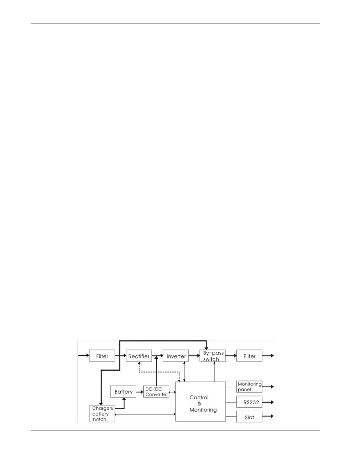
As shown in block diagram:
An input lter reduces transients on the incoming ulity.
To maintain full baery charge, the AC input power is reced and regulated in the recer feeding power
to the baery converter and inverter.
DC power is converted to AC in the inverter, passing it on to the load.
Power is maintained from the baery during a power failure.
The converter increases voltage appropriately for the inverter.
Xtreme Power Conversion Corporaon
NXRTi Users Manual
Page 7
Uninterrupble Power Supply
Funcons and Characteriscs
Advanced IGBT modules are used in our UPS, with electronics that will work for more than 300,000 hours.
Digital Control Technology with high eciency algorithm delivers a most reliable controller design used to
opmize the output parameters of the UPS.
The UPS performs a Self-Diagnosc Test before starng, enabling the UPS to detect and correct any poten-
al problems prior to powering up the load.
Double Conversion On-Line Topology makes the output of the UPS a pure sine wave with consistent fre-
quency and voltage regulaon, low noise, and no interrupon in power to the load when ulity power is
lost.
Zero Transfer Time when the ulity power fails or returns.
The UPS has a Bypass Funcon that allows for the load to be transferred to a bypass mode when a UPS
fault occurs. No interrupon in power occurs to the load and an alarm will alert to this occurrence. This
feature also allows for conguring the UPS to support fully rated loads of switching power supplies, as the
bypass circuit can handle the start up.
Advanced Voltage Compensaon Technology allows the input voltage range to be 115VAC to 295VAC,
reducing baery usage and enhancing UPS response during ulity power uctuaons.
Advanced Wide Input Frequency Technology enables the UPS to perform from 45 to 55 Hz when 50Hz
output is selected, or 55 to 65 Hz when 60Hz output is selected. All of this means that the UPS is very
compable with single-phase generator operaon.
Advanced Power Factor Correcon (PFC) Technology on the input of the UPS makes the input power fac-
tor more than 0.98, increasing power eciency, removing harmonic noise, and lowers the UPS operaonal
cost.
Auto Start on Baery allows the UPS to start in baery mode when ulity power is not available.
Rack-Tower Conversion LCD means that the display can be read in Rack or Tower conguraons by only
pressing a buon the display electronically rotates to provide the detailed informaon in an easy-to-read
manner.
ECO Funcon can help to save electricity by allowing the UPS to operate in a line-interacve mode. The
load is supplied with ulity power directly while the inverter is in a standby mode unl needed.
System Conguraon
The UPS device and the internal baeries make up the system. Depending on the site and load requirements of the
installaon, certain addional opons are available for the soluon.
Planning a UPS system, the following should be taken into consideraon:
The total demand of the protected system shall dictate the output power rang (VA). Allow a margin for
future expansion or calculaon inaccuracies from measured power requirements.
Backup me required will indicate the baery size needed. If the load is less than the UPS nominal power
rang, then actual backup me is longer.
The following opons are available:
τ Extended Baery Packs
» NXRTi-EBP1 for 1000
» NXRTi-EBP2 for 2000
» NXRTi-EBP3 for 3000
τ Connecvity Opons –SNMP/WEB card
τ Xtreme Power Distribuon Units (XPDU)
See the Specicaon secon of this manual for addional model informaon.
Xtreme Power Conversion Corporaon
NXRTi Users Manual
Page 8
Uninterrupble Power Supply
NXRTi front view
NXRTi-1000 rear view
NXRTi-2000 and NXRTi-3000 rear view
Xtreme Power Conversion Corporaon
NXRTi Users Manual
Page 9
Uninterrupble Power Supply
LED Descripon
The UPS has four LEDs on the front control panel. These LED’s allow the user to quickly understand if any acon
is needed.
Red LED
If this WARNING LED is illuminated it indicates a fault and the UPS will have no output. Faults that would indicate
this alarm condion include:
Overload
Inverter fault
BUS fault
Over temperature fault
Yellow LED
If this BYPASS LED is illuminated it indicates the user needs to take some acon, and included:
UPS in Bypass Mode
If this BATTERY LED is illuminated it indicates the user needs to take some acon, and included:
UPS operang on baery
Baeries Overcharged
Charger fault
Fan fault
Baeries discharged to low voltage level
Green LED
If this INVERTER LED is illuminated it indicates that everything is normal and the UPS is being powered by incoming
AC ulity or by the baeries.
Aer starng the UPS, the four LED’s will light and go out one-by-one, cycling unl the UPS starts successfully.
Xtreme Power Conversion Corporaon
NXRTi Users Manual
Page 10
Uninterrupble Power Supply
LCD Descripons
The LCD display electronically rotatable by PRESS and HOLD the ROTATE buon for more than 1 second.
NXRTi buons
NXRTi LCD Panel in Tower Mode
NXRTi LCD Panel in Rack Mode
The LCD display contains
Numerical value secon
This secon displays the corresponding numerical value of output, load, temperature, input, and baery. Example:
Output Voltage = 220V; Output Frequency = 50Hz
Capacity graphics secon
This secon displays the capacity of the baery and amount of load on the UPS output. Each pane represents 20%
capacity. When the capacity of the baery is 80-100% 5 panes would be displayed. When the load reaches 40-60%
Xtreme Power Conversion Corporaon
NXRTi Users Manual
Page 11
Uninterrupble Power Supply
3 panes would be displayed. When the UPS is in overload, the icon will ash. When the capacity of baery is too
low or disconnected, the icon will also ash.
Fan status graphics secon
This secon displays if the fan works normally. When the fan is working normally, it will show the dynamic fan
blades rotang. If the fan fails or works abnormally, the icon will keep ashing and alarm.
Charger status graphics secon
The secon displays the status of the charger. When the charger is working normally, the corresponding icon will
vary dynamically and orderly.
When the charger works abnormally, the icon will ash as shown below.
When the UPS is in Baery Mode, the number of icons for the charger status secon will vary according to the
changeable capacity of the baery. For example, there are ve panes in the gure below, so the corresponding
number of icons is ve rows.
Xtreme Power Conversion Corporaon
NXRTi Users Manual
Page 12
Uninterrupble Power Supply
RS-232 Standard Interface
The RS-232 interface uses a 9-pin female D-sub connector. Informaon provided includes data about ulity, load
and the UPS. The interface port pins and their funcons are idened in the following table:
PIN # FUNCTIONS
1,4,6,7,8 NOT USED
2 TRANSMIT
3 RECEIPT
5 GND
9 REMOTE WAKE UP
CAUTION: MAX RATED VALUES 12VDC
SNMP Communicaons Opon
The UPS provides an intelligent slot for internal or external network card. This special intelligent network card can
be compable with popular soware and hardware found on the web and in operang systems. It can support op-
erang systems such as HP Open View, IBM Netview, SUN Netmanager, etc. This enables the UPS to provide instant
UPS and power informaon over the network. Please contact your reseller for addional details.
Determining the Power Requirements of Your Equipment
1. Make sure the total Volt-Amp (VA) requirements of your connected equipment does not exceed the maxi-
mum VA rang for the UPS. The maximum VA rangs are shown in the Specicaons secon of this docu-
ment.
2. Ensure that the equipment plugged into the baery-powered outlets does not exceed the UPS rated ca-
pacity. If UPS rated capacies are exceeded, an overload condion may occur and cause the UPS to shut
down and trip the circuit breaker.
3. If the power requirements of your equipment are listed in values other than Volt-Amps (VA), convert Was
(W) or Amps (A) into VA by doing the calculaons below. Note: The equaon below only calculates the
maximum amount of VA that the equipment can use, not what is typically used by the equipment at any
given me. Users should expect usage requirements to be approximately 60% of the value to esmate
power requirements:
Was (W) x 1.43 = _____ VA or _____ Amps (A) x 230 Volts (V) = _____ VA
Add the totals for all of the equipment and mulply this total by 0.65 to calculate actual power require-
ments.
Note: Many factors can aect the amount of power that your computer system will require. The total load
that you will be placing on the baery-powered outlets should not exceed 85% of the UPS capacity.
Xtreme Power Conversion Corporaon
NXRTi Users Manual
Page 13
Uninterrupble Power Supply
Hardware Installaon Guide
Inspect the UPS upon receipt. The packaging is recyclable; keep it for reuse or dispose of properly.
Safety Informaon
Informaon presented here is vital to all personnel. Please read all Safety informaon.
Storage and Transportaon
Please handle the UPS and associated equipment with extreme cauon since a high amount of energy is contained
in the baeries. Always keep the unit in an upright posion as marked on the packaging, and never drop the unit.
Please adhere to the following instrucons if the UPS is not installed immediately:
Store the equipment as is in its original packing and shipping carton.
Do not store in temperatures outside the range of -15°C to +25°C
Ensure that the equipment is fully protected from wet or damp areas and from moist air.
In order to maintain the baeries, the UPS should be recharged every 6 months for at least 8 hours.
If ammable substances such as gases or fumes are present, or if the room is airght, a hazardous situaon may
exist in which no electrical equipment should be operated.
The instrucons in this manual explain how to install the UPS safely. Not acknowledging such electrical hazards
may be fatal – keep this manual for future reference.
WARNING!
It is strongly recommended that the UPS cabinet not be opened as components have very high volt-
age and touching those components may be fatal. Only a qualied technician or authorized agent
may service the unit.
The UPS units output receptacles carry live voltage even when not connected to an input voltage
source. The UPS has its own internal energy source.
Environment
Ensure that all environmental concerns and requirements are met according to specicaons listed in this docu-
ment, otherwise the safety of installaon personnel cannot be guaranteed, and the unit may malfuncon.
Ensure that you remember the following when locang the UPS system and baery opons:
Avoid extremes of temperature and humidity. Maximum baery life can be aained with a recommended
temperature range of +15°C to +25°C.
Provide protecon for the equipment from moisture.
Space and venlaon requirements must be met. Ensure there is 100mm behind and 50mm on the sides
of the UPS for proper venlaon.
Ensure that the front of the UPS remains clear for user operaon.
Xtreme Power Conversion Corporaon
NXRTi Users Manual
Page 14
Uninterrupble Power Supply
Installaon
Plasc Base Installaon (for use in Tower conguraon)
Two plasc base brackets interconnect and aen for holding 2U base unit conguraon.
The same plasc base assembly plus a 1U plasc base extension bracket are connected together as shown below
to accommodate 3U enclosures.
Xtreme Power Conversion Corporaon
NXRTi Users Manual
Page 15
Uninterrupble Power Supply
Xtreme Power Conversion Corporaon
NXRTi Users Manual
Page 16
Uninterrupble Power Supply
19” Cabinet Ear Installaon
The bracket is installed on the UPS as shown below
UPS Front Corner UPS Rack Bracket
UPS Front Corner With Bracket Installed
Xtreme Power Conversion Corporaon
NXRTi Users Manual
Page 17
Uninterrupble Power Supply
Tower Assembled Unit
Rack Assembled Unit
Xtreme Power Conversion Corporaon
NXRTi Users Manual
Page 18
Uninterrupble Power Supply
Inial Connecon and Startup
Ensure that the UPS and oponal baery packs are mounted correctly, and the UPS is disconnected from input
power before proceeding.
1. Connect external baery packs (opon)
CAUTION: CONNECT ONLY BATTERY PACKS PROVIDING THE SAME DC VOLTAGE AS THE UPS – PLEASE DOU-
BLE CHECK LABELING ON THE UPS AND BATTERY PACKS TO ASSURE PROPER VOLTAGES ARE CONNECTED.
CONNECTING THE INCORECT BATTERY PACK TO THE UPS MAY RESULT IN DAMAGE TO THE UPS AND/OR BAT-
TERY PACK THAT WILL VOID THE WARRANTY.
Ensure that the UPS is disconnected from AC input and is o while connecng the External Baery Packs.
Ensure all baery breakers are in the “OFF” posion.
Remove the EBP covers on the UPS and EBP. Connect the baery cable that comes with the External Bat-
tery Pack between the External Baery Pack to the UPS.
Secure the DC baery cable to the rear of the UPS, and the rear of the EBP by using M3 x 8 screws provided
(2 each per connector end).
Connect the input power cord from the EBP to an input AC ulity source per specicaons.
Connect a second baery pack to the rst EBP in the same fashion if more than one is to be installed.
Refer to Appendix A: Baery Pack User Manual for more details
2. Connect SNMP card (opon)
Remove the two screws securing the SNMP cover plate on the rear of the UPS, and slide the SNMP NetA-
gentII card into the slot. Secure the card into the slot with the two screws previously removed.
3. Close the baery breakers on the Oponal baery packs if installed.
4. Connect the AC input cable to the UPS and connect the other end to an approved grounded outlet. Once
the UPS has been connected to an AC power source the internal charger will start charging the UPS baeries,
at this point the yellow LED is illuminated, and the LCD displays “UPS OFF”. In this state the output voltage is
zero, which means UPS has no output. Please realize that although you may start using the UPS immediately,
maximum back-up me will sll not be available, so it is recommended to charge the baeries for a minimum
of 6 hours before use.
5. Start and congure the UPS
Front Panel Buons
ON/OFF BUTTON
Press and hold buon(s) for more than ½ second to turn on or turn o the UPS
Xtreme Power Conversion Corporaon
NXRTi Users Manual
Page 19
Uninterrupble Power Supply
ROTATE BUTTON
Press and hold buon(s) for more than 2 seconds to rotate the LCD in any mode
SELF-TEST / MUTE BUTTON
Press and hold buon(s) for more than 1 second in ulity mode or ECO mode to operate UPS Self-Test
Press and hold buon(s) for more than 1 second in baery mode to operate the Mute Funcon
INQUIRE BUTTON
Press and hold the buon(s) for more than ½ second but less than 2 seconds to change inquire funcon
Press and hold this buon for more than 2 seconds to change display informaon
FUNCTION SETTING MODE
Press and hold this buon for more than ½ second but less than 2 seconds to set opons
NON-FUNCTION SETTING MODE
Press and hold the buon for more than 2 seconds
6. Congure the local monitoring soware if desired.
Insert the UPSilon 2000 CD (included with UPS packaging) into the CD ROM of the local computer.
Select “Install program” from the Autorun menu and choose for the correct operang system.
Follow the setup instrucons. Enter the product key when prompted. The soware key is found on the CD
cover. Click nish when prompted.
The UPSILON icon will appear in the system tray of the desktop near the system clock. Double click this
icon to enlarge the program window.
Connect the RS232 cable (included in the UPS packaging) to the Computer and UPS. Communicaon
should start momentarily. If it does not, click on Sengs up on the UPSilon toolbar, then select a dierent
Comport unl communicaon is established.
Click on “Manual” in the UPSILON toolbar for further soware conguraon.
NOTE: PLEASE VERIFY AUTOMATIC SHUTDOWN TIME PARAMETERS IN THE SETTINGS SECTION FOR YOUR
SPECIFIC INSTALLATION.
7. Congure the oponal NetAgentII SNMP card if installed.
Insert the NetAgent Ulity CD (included with SNMP packaging) into a PC and download the user manual
Install Nelity from the AutoRun menu
Connect a network cable from the PC to the SNMP card.
Run Nelity program and it will auto-search and list available NetAgents (SNMP card)
Highlight and click “Congure” to change the network sengs on the NetAgent discovered.
Disconnect the cable to the PC and connect the SNMP card to your network.
Access the SNMP card via the network and make conguraon changes using the manual downloaded
previously.
Xtreme Power Conversion Corporaon
NXRTi Users Manual
Page 20
Uninterrupble Power Supply
NOTE: PLEASE VERIFY AUTOMATIC SHUTDOWN TIME PARAMETERS IN THE SETTINGS SECTION FOR YOUR
SPECIFIC INSTALLATION.
8. Aer charging is complete, connect the loads to the UPS while monitoring the load levels via the UPS LCD
or via the soware.
Do not connect any devices that have the possibility of overloading the UPS.
Refer to the Troubleshoong secon and/or Technical Support with any problems during setup.
Users Operaons
The only operaons that users are permied to do are:
Turning the UPS unit ON or OFF
Operang the user interfaces
Connecng data interface cables
All such operaons are to be performed exactly as instructed in this manual. The greatest care possible must be
taken for any of these operaons, and any change thereof may prove very hazardous to the operator.
Turning O the UPS When Connected to an AC Source
Once ulity power is plugged in, the UPS will charge the baery, at the moment, LCD shows that the out-
put voltage is 0, which means UPS has no output. If it is expected to have output of bypass, you can set
the bps “ON” by LCD seng menu.
Press and hold the ON/OFF key for more than half a second to start the UPS, then it will start the inverter.
Once started, the UPS will perform a self-test funcon, LED will light and go out circularly and orderly.
When self-test nishes, it will come to line mode, the corresponding LED lights, UPS is working in line
mode.
Starng the UPS From a DC Source (Cold Start)
When ulity power is disconnected, press and hold the ON/OFF key for more than ½ second to start UPS.
The operaon of the UPS in cold start is almost the same as that when ulity power is available. Aer n-
ishing the self-test, the corresponding LED lights and UPS are working in baery mode.
Turning O the UPS When in Ulity Mode
Press and hold the ON/OFF key for more than ½ second to turn o the UPS and inverter.
Aer the UPS shuts down, the LEDs go out and there is no output. If output is needed, you can set bps
“ON” by LCD seng menu.
Turning O the UPS When in Baery Mode
Press and hold the ON/OFF key for more than ½ second to turn o the UPS.
When turning o the UPS, it will do a self-test rst, then the LED light and LCD display will turn o.
Self Test & Mute Test Operaon
When the UPS is in on-line mode, Press and Hold the Self-Test / Mute Buon for more than 1 second, the
LED lights and go out in order. The UPS arrives then at its Self-Test Mode and tests its status. The UPS will
  • Page 1 1
  • Page 2 2
  • Page 3 3
  • Page 4 4
  • Page 5 5
  • Page 6 6
  • Page 7 7
  • Page 8 8
  • Page 9 9
  • Page 10 10
  • Page 11 11
  • Page 12 12
  • Page 13 13
  • Page 14 14
  • Page 15 15
  • Page 16 16
  • Page 17 17
  • Page 18 18
  • Page 19 19
  • Page 20 20
  • Page 21 21
  • Page 22 22
  • Page 23 23
  • Page 24 24
  • Page 25 25
  • Page 26 26
  • Page 27 27
  • Page 28 28
  • Page 29 29
  • Page 30 30
  • Page 31 31
  • Page 32 32
  • Page 33 33
  • Page 34 34
  • Page 35 35
  • Page 36 36
  • Page 37 37

Xtreme NXRTi 3000VA User manual

Category
Uninterruptible power supplies (UPSs)
Type
User manual
This manual is also suitable for

Ask a question and I''ll find the answer in the document

Finding information in a document is now easier with AI