Cisco Systems Cisco MGX 8950
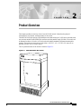
The Cisco MGX 8950 is a high-capacity ATM backbone switch that provides up to 240 Gbps of switching capacity. It supports a variety of ATM interfaces, including OC-48, OC-12, OC-3, T3, and E3. The MGX 8950 can be used to interconnect ATM networks, provide high-speed access to ATM services, and create resilient ATM networks.
Key features of the Cisco MGX 8950 include:
- Up to 240 Gbps of switching capacity
- Support for a variety of ATM interfaces
- Redundant power supplies and fans
- Hot-swappable modules
- Advanced traffic management features
The Cisco MGX 8950 is ideal for use in:
Cisco Systems Cisco MGX 8950
The Cisco MGX 8950 is a high-capacity ATM backbone switch that provides up to 240 Gbps of switching capacity. It supports a variety of ATM interfaces, including OC-48, OC-12, OC-3, T3, and E3. The MGX 8950 can be used to interconnect ATM networks, provide high-speed access to ATM services, and create resilient ATM networks.
Key features of the Cisco MGX 8950 include:
- Up to 240 Gbps of switching capacity
- Support for a variety of ATM interfaces
- Redundant power supplies and fans
- Hot-swappable modules
- Advanced traffic management features
The Cisco MGX 8950 is ideal for use in:


-
 1
1
-
 2
2
-
 3
3
-
 4
4


Cisco Systems MGX 8950 User manual
- Type
- User manual
- This manual is also suitable for
Cisco Systems Cisco MGX 8950
The Cisco MGX 8950 is a high-capacity ATM backbone switch that provides up to 240 Gbps of switching capacity. It supports a variety of ATM interfaces, including OC-48, OC-12, OC-3, T3, and E3. The MGX 8950 can be used to interconnect ATM networks, provide high-speed access to ATM services, and create resilient ATM networks.
Key features of the Cisco MGX 8950 include:
- Up to 240 Gbps of switching capacity
- Support for a variety of ATM interfaces
- Redundant power supplies and fans
- Hot-swappable modules
- Advanced traffic management features
The Cisco MGX 8950 is ideal for use in:
Ask a question and I''ll find the answer in the document
Finding information in a document is now easier with AI
Related papers
-
Cisco MGX-FRSM-2CT3 User manual
-
-
Cisco Systems 8800 User manual
-
-
-
-
-
-
-
Other documents
-
-
Cisco MGX 8830 ATM Multiservice Switch Configuration Guide
-
Sentinel PXM-2 User manual
-
3com CoreBuilder 9000 ATM Interface Module Quick start guide
-
Tascam Portastudio 2488 User manual
-
-
Tascam 2488 User manual
-
-
Lucent Technologies Stinger OC12-ATM User manual
-
Cisco MGX 8950 Specification