Page is loading ...

CHAPTER
Card and Service Configuration 6-1
6
Card and Service Configuration
This chapter describes how to configure the MGX 8850 cards and the services they support.
Although the presumption for this chapter is that a plan exists for your network, it reviews some of
the information that supports network planning. Generic instructions for inserting and removing
cards appear in “Chapter 4, “Enclosure and Card Installation.”
The services and applicable modules described in this chapter are:
• Physical and logical configuration of a broadband interface on the Processor Switching Module
(PXM) and, for a stand-alone switch, connection addition
• ATM service on the MGX-AUSM/B
• Frame Relay service on the following service modules:
MGX-FRSM-2CT3
MGX-FRSM-2T3E3
MGX-FRSM-HS2
MGX-FRSM-HS1/B
AX-FRSM-8T1 and AX-FRSM-8E1
• Circuit emulation service on the MGX-CESM-8T1 and MGX-CESM-8E1
• Redundancy and bulk distribution on the Service Resource Module-3T3 (MGX-SRM-3T3/B)
Note For information on the Route Processor Module (RPM), see the Cisco Route Processor
Module Installation and Configuration Guide.
Tasks for Configuring Cards and Services
This section contains a general description of the sequence of tasks for configuring the cards and
their services. It also contains details on how to configure resource partitions and add local
connections and three-segment connections. Detailed descriptions of these tasks for individual cards
appear in subsequent sections.
Modifying the Resource Partitioning
A resource partition at the card level consists of a number of logical connections (LCNs). At the port
level, a resource partition consists of a percentage of bandwidth, a DLCI or VPI/VCI range, and the
number of logical connection numbers (LCNs) available to a network control application. On the

Tasks for Configuring Cards and Services
Cisco MGX 8850 Installation and Configuration, Release 1.1.00, Part Number 78-6186-02
6-2
PXM, the connections are global logical connections (GLCNs). By default, all resources on a a card
or logical port are available to any controller on a first-come, first-served basis. If necessary, you can
modify the resource partitioning at the card level or logical port level. Port-level resource
modification follows card-level modification, so the available port-level resources depend on
whether and how much you change the card-level resource partitioing. You do not have to change
the resource partitioning for the card before changing resource partitioning for a port.
The current network control application is Portable AutoRoute (PAR). Planning considerations
should include the possibility of modifying the partitioning of resources for the interface. For
example, the MGX 8850 switch has the capacity to support a Cisco Multi-Protocol Label Switching
(MPLS) controller or a Private Network to Network Interface (PNNI) controller.
Sequence of Configuration Tasks
In a new switch, the common approach is to configure the same aspect for all cards at once—adding
logical ports to all applicable cards, for example. In contrast, the likely sequence for installing a
single card is to begin with its card-level features and continue until you have configured every
connection. The common tasks for a new switch are:
1 Optionally configure the service modules (except the RPM) for redundancy. This card-level
operation requires redundant cards and possibly an MGX-SRM-3T3/B.
2 Optionally configure resource partitioning for the whole card if the default partitioning does not
fulfill the purpose of the card.
3 Activate physical lines.
4 Configure the line if default parameters are not appropriate.
5 Create the logical ports then modify them as needed.
6 Optionally configure resource partitions for a logical port if the default partitioning does not
support the intended operation of the port.
7 Add connections then modify them as needed.
Rules for Adding Connections
This section describes the rules for adding local connections, three-segment connections, and
management connections. The MGX 8850 switch can support:
• Local-only, digital access and cross-connect (DAX) connections
• Three-segment connections across an ATM or Frame Relay network
• IP management connections (stand-alone switches only)
A management connection is an inband IP connection that lets a workstation control a local or
remote MGX 8850 switch through a service module rather than the Ethernet port on a PXM-UI.
Although the rules include references to CLI syntax, they also apply to the Cisco WAN Manager
application.

Card and Service Configuration 6-3
Rules for Adding Connections
Rules for Adding a DAX Connection
A DAX con is a connection whose endpoints for the entire connection exist on the same switch. The
following apply to the MGX 8850 switch:
1 On a feeder, a DAX con can exist between different service modules or the same service module.
2 A stand-alone node supports DAX cons with one or both endpoints on the PXM in addition to
DAX cons between service modules.
3 Either endpoint can be the master.
4 The first endpoint to add is the slave. The generic syntax is:
addcon <local parameters>
where local parameters are the port, DLCI or VPI and VCI, and mastership status. Slave is the
default case, so you actually do not explicitly have to specify it. When you press Return, the
system returns a connection identifier. The identifier includes the port and DLCI or VPI and VCI.
Use the identifier to specify the slave endpoint when you subsequently add the connection at the
master end. The slave endpoint is specified as the remote parameters in item 5.
5 To complete the DAX con, add the master endpoint. The generic syntax is
addcon <local parameters> <remote parameters>
where local parameters are the port, DLCI or VPI and VCI, and mastership status (master in this
case). The remote parameters are the items in the connection identifier that the system returned
when you added the slave endpoint.
6 If the endpoint is a PXM port in a stand-alone node, specify the slot as 0. The addcon command
is the only command in which you specify the slot number for the PXM as 0.
Rules for Adding Three-Segment Connections
A three-segment connection consists of a local segment on each MGX 8850 switch at the edges of
the network cloud and a middle segment across the network cloud. The MGX 8850 requirements are:
1 For MGX 8850 feeders, the backbone must consist of BPX 8600-series switches.
2 For MGX 8850 stand-alone switches, the backbone switches can be either BPX 8600-series
switches or switches from another manufacturer.
3 On a feeder, the local segment exists between a service module and the PXM.
4 On a stand-alone node, the local segment can be between a service module and a port on the PXM
or just two ports on the PXM.
5 For the local segment, add the connection at only the master endpoint. The generic syntax is:
addcon <local parameters> <remote parameters>
where local parameters are the port, DLCI or VPI and VCI, and mastership status (master in this
case). The remote parameters are the current nodename, slot, port, and VPI and VCI of the slave
end. For the PXM endpoints, specify the slot number as 0. The addcon command is the only
command in which you specify the slot number for the PXM as 0.

Tasks for Configuring Cards and Services
Cisco MGX 8850 Installation and Configuration, Release 1.1.00, Part Number 78-6186-02
6-4
Rules for Adding Management Connections
This section describes the requirements for adding an inband ATM PVC for managing an MGX 8850
stand-alone node. A management connection lets a workstation connected through a router control
either the local MGX 8850 node or a remote MGX 8850 node that has no workstation. The typical
configuration has the connecting router feed an AUSM/B, FRSM, RPM, or PXM UNI port.
A management connection can be either a DAX con or a three-segment connection. The maximum
number of management connections is eight. The DAX con exists between a service module or PXM
UNI and port 34 of the local PXM. PXM port 34 is a reserved port for management connections on
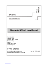
a stand-alone node. The network in Figure 6-1 shows FRSMs in a feeder application.
A three-segment management connection has a:
1 Local segment between a near-end service module or PXM UNI and a PXM port in the
range 1–32.
2 Middle segment across the network cloud.
3 Local segment between a remote PXM port in the range 1–32 and port 34 of that same PXM.
The path from “A” to “B” in Figure 6-1 consists of three segments. A segment exists between the
FRSM and the PXM on each MGX 8850 switch. The middle segment exists between the BXMs at
the edges of the ATM cloud and may traverse BPX 8600 via nodes in the cloud. The VPI and VCI
at each BPX8600-series switch connected to an MGX 8850 feeder must match the VPI and VCI on
the slave endpoint of the connected PXM. The VPIs and VCIs at the endpoints of the middle segment
do not have to match. If you use the CLI rather than the Cisco WAN Manager application, add each
segment through the CLI at each switch.
Figure 6-1 Frame Relay Connection Through an MGX 8850-BPX 8600-Series Network
BPX 8620
Backbone
Network
BPX
8620
F
R
S
M
Port
T1
Channel
A
A
BPX
8620
F
R
S
M
Port
T1
Channel
B
B
Customer Equipment
to BPX 8620
Customer Equipment
to BPX 8620
BPX 8620 to BPX 8620
BXM-8-155
BXM-8-155
17910
MGX
8850
MGX
8850

Card and Service Configuration 6-5
The Processor Switching Module
The Processor Switching Module
This section first describes how to activate and configure the card-level parameters, lines, and ports
on the PXM uplink card then describes how to add connections to the PXM in a stand-alone node.
The descriptions tell you how to:
• Optionally modify the resource partitioning at the card level.
• Activate a line on the uplink card. On a stand-alone node, you can activate more than one line if
the uplink card has multiple lines. One physical line must be the trunk to a network routing node.
• If the switch has a pair of SRMs for bulk distribution and you use the CLI rather than the
CiscoView application, activate the SRM lines from the PXM.
• Optionally modify the resource partitioning at the port level.
• Create logical ports.
• On a stand-alone node, specify the cell header type. UNI cell headers typically apply where a
workstation connects to a UNI port on the uplink card rather than a port on the PXM-UI card.
Such an implementation is not common.
• On a stand-alone node, add standard connections and optional management connections.
• On a stand-alone node, configure Automatic Protection Switching (APS).
• For a feeder, execute steps on the connected BPX 8600-series switch to make the feeder an
available resource in the network.
Note For a description of the bit error rate test (BERT) functions, see the section titled “Bit Error
Rate Testing Through an MGX-SRM-3T3.”

The Processor Switching Module
Cisco MGX 8850 Installation and Configuration, Release 1.1.00, Part Number 78-6186-02
6-6
Configuring Card-Level Parameters, Lines, and Ports
This section describes how to configure card-level features, activate a physical line, and configure
logical elements such as a port. If necessary, refer to the section titled “Tasks for Configuring Cards
and Services” for background information on these types of tasks.
Step 1 Optionally, you can modify the resource partitioning for the whole card by executing
cnfcdrscprtn. You can view resource partitioning through dspcdrscprtn.
cnfcdrscprtn <number_PAR_conns> <number_PNNI_conns> <number_TAG_conns>
• number_PAR_conns is the number of connections in the range 0–32767 for PAR.
• number_PNNI_conns is the number in the range 0–32767 available to PNNI.
• number_TAG_conns is the number of connections in the range 0–32767 for MPLS.
For example, you could reserve 10,000 connections for each controller on the PXM with:
cnfcdrscprtn 10000 10000 10000
Step 2 Activate a line by executing addln:
addln -ds3 <slot.line> | -e3 <slot.line> | -sonet <slot.line>
• -ds3 indicates a T3 line parameter follows.
• -e3 indicates an E3 line parameter follows.
• -sonet indicates an OC-3 or OC-12 line parameter follows.
• slot is 7 or 8 for the PXM. If the switch has a single of redundant pair of SRMs,
execute addln for slots 15, 16, 31, and 32.
• line has the range 1–4 but depends on the number of lines on the back card.
For a feeder, you can activate only one line. For a stand-alone, you can activate more than
one line if the back card has multiple lines. One line must serve as the trunk to the ATM
network. With an OC-3, T3, or E3 card, remaining lines can serve as UNI ports to CPE.
Step 3 If necessary, modify the characteristics of a line by using cnfln.
Step 4 Configure logical ports for the physical line by executing addport. Execute addport
once for each logical port. Related commands are cnfport, dspports, and delport.
addport <port_num> <line_num> <pct_bw> <min_vpi> <max_vpi>
• port_num is the number for the logical port. The range is 1–32 for user-ports or 34 for
inband ATM PVCs that serve as management connections.
• line_num is the line number in the range 1–4 but depends on the type of uplink card.
• pct_bw is the percentage of bandwidth. The range is 0–100. This parameter applies to
both ingress and egress.
• min_vpi is the minimum VPI value. On a feeder, the range is 0–4095. On a stand-alone
node, the range is 0–255.
• max_vpi is the maximum VPI value. On a feeder, the range is 0–4095. On a
stand-alone node, the range is 0–255.

Card and Service Configuration 6-7
Automatic Protection Switching on the PXM
Using an example of 100% of the bandwidth on one logical port 1:
addport 1 1 100 1 200
where the first “1” is the logical port number; the second “1” is the line number on the
PXM back card to which you are assigning this logical port number; “100” is the
percentage of bandwidth this port has in both directions; and the VPI range is 1–200.
Step 5 If necessary, use cnfportrscprtn to modify port-level resources for a controller:
cnfportrscprtn <port_no> <controller> <ingress_%BW> <egress_%BW>
• <min_VPI> <max_VPI> <min_VCI> <max_VCI> <max_GLCNs>
• port_no is the logical port number in the range 1–32 for user-connections or 34 for
inband ATM PVCs for network management.
• controller is a string identifying the network controller—”PAR,” “PNNI,” or “TAG.”
• ingress_%BW is the percentage of ingress bandwidth in the range 0–100.
• egress_%BW is the percentage of egress bandwidth in the range 0–100.
• min_vpi is the minimum VPI in the range 0–4095.
• max_vpi is the maximum VPI in the range 0–4095.
• min_vci is the minimum VCI in the range 0–65535.
• max_vci is the maximum VCI in the range 0–65535.
• max_chans is the maximum GLCNS in the range 0–32767.
Step 6 On a stand-alone node, specify the cell header type as needed by executing cnfatmln.
cnfatmln <line_num> <type>
• line_num is the line number in the range 1–4.
• type is either 2 for UNI or 3 for NNI (the default).
UNI cell headers typically apply where a workstation connects through a line to a PXM
UNI port (rather than a SLIP-based port on the PXM-UI card). Such an implementation
is not common, so cnfatmln usually is not necessary.
Automatic Protection Switching on the PXM
Automatic Protection Switching (APS) provides redundancy for an OC-3 or OC-12 line on the PXM
if a failure occurs someplace other than the PXM front card. The failure can originate on the daughter
card, uplink card, or any part of the physical line. With APS, the active PXM remains active and
passes the cells from the failed line-path through the redundant line. The advantage of APS is that a
line switchover requires significantly less time than a full PXM switchover. (A failure of the PXM
front card in a redundant system causes the entire PXM card set to switch over.) As defined in
GR-253, a variety of APS modalities are possible (see the command summaries that follow).
The current requirements for APS service on an MGX 8850 switch are:
• Redundant PXMs (currently, the PXM does not support an APS configuration where the working
and protection lines on the same uplink card).
• A “B” version of an OC-3 or OC-12 back card (SMLR-1-622/B, and so on).
• The connected network switch or CPE must also support APS.

The Processor Switching Module
Cisco MGX 8850 Installation and Configuration, Release 1.1.00, Part Number 78-6186-02
6-8
Initial APS specification consists of the working and protection slot and line and the mode for APS.
After the initial APS specification, you can configure additional APS parameters, give commands
for switching lines, and display the APS configuration. The CiscoView application and CLI provide
access to the APS feature. For detailed descriptions of the CLI commands, see the Cisco MGX 8850
Wide Area Edge Switch Command Reference. Note that APS is available for only the “B” versions
of the SONET cards—SMLR-1-622/B, and so on. The applicable CLI commands are:
• addapsln to specify the lines and mode for APS
• cnfapsln to modify the following details of APS operation:
— error thresholds
— wait period before the PXM restores the working line after errors clear
— unidirectional or bidirectional switchover, which specifies whether one or both directions of
a line are switched when the criteria for a hard or soft failure are met for one direction
— revertive recovery, where the working line automatically returns to operation after errors
clear and any wait period has elapsed
— enable use of K1 and K2 bytes in the line-level frame for equipment at both ends to exchange
APS-related information
• delapsln to delete the APS configuration
• dspapsln to display the configuration for an APS-configured line
• switchapsln to issue commands for line switching that:
— clear previous user requests
— lock out (block) line switching
— manually switch to the protection line if the following are true: no errors exist, the working
line is active, and your request has an equal or higher priority than the last switch request.
— force a line switch regardless of existing errors the following are true: the working line is
active and your request has an equal or higher priority than the last switch request.
— switch all traffic to either the working lines or protection lines so you can remove a card
(applies to only the currently supported configuration of 1+1 mode on two uplink cards)
To specify APS, use the following syntax:
addapsln <workline> <workingslot> <protectionline> <protectionslot> <archmode>
where workline and workingslot identify the line and slot of the APS working line, and protectionline
and protectionslot identify the protection line and slot. According to GR-253, the archmode
identifies the type of APS operation. The mode definition includes:
1 1+1 on one back card
2 1+1 on two back cards
3 1:1
4 Annex B
Currently, the only supported mode is 1+1 with two uplink cards (mode=2). With 1+1 APS, both the
working line and the protection line carry duplicate data even though no error threshold has been
exceeded or line break has occurred. This mode requires that two standard cables (rather than a
Y-cable) connect at two ports on the equipment at the opposite end. With the two-card
implementation, workline must be the same as protectionline.

Card and Service Configuration 6-9
Adding Connections on a PXM in a Stand-Alone Node
Adding Connections on a PXM in a Stand-Alone Node
This section describes the CLI commands for provisioning connections on a PXM in a stand-alone
node. Connection addition abides by the rules for a standard connection or a management connection
in the form of either a three-segment connection or a DAX con. See “Rules for Adding Connections”
earlier in this chapter. In addition this section describes the commands for modifying certain features
for a connection and policing connections by way of usage parameter control.
The CLI commands correspond to functions in the Cisco WAN Manager application. The preferred
CLI command is addcon. (If the application requires NSAP addressing, use addchan to add the
connection and cnfchan if you need to modify it. Refer to the command reference for the syntax.)
In addition, On the PXM CLI:
Step 1 Execute the addcon command according to the following syntax:
addcon <port_num> <conn_type> <local_VPI> <local_VCI> <service> [CAC]
[mastership] [remoteConnId]
• port_no is the logical port in the range 1–32 for a user connection or 34 for
management connection.
• conn_type is a number identifying the connection type—1 for VPC or 2 for VCC.
• local_VPI is the local VPI in the range 0–4095.
• local_VCI is the local VCI in the range 0–65535.
• service is a number in the range 1–4 to specify the type of service: 1=CBR, 2=VBR,
3=ABR, and 4=UBR.
• CAC optionally lets you turn off the addition of the loading affect of a connection to
the aggregated load on a port.
• mastership specifies whether the endpoint you are adding is the master or slave.
1=master. 2=slave (default). The syntax shows this parameter as optional because you
need to enter it at only the master end. Slave is the default, so you do not explicitly
need to specify it when entering a DAX con.
• remoteConnId identifies the connection at the slave end. The format for remoteConnId
is Remote_nodename.slot_num.remote_VPI.remoteVCI. Note that the slot number of
the active PXM is always 0 when you add a connection because the PXM slot number
is a fixed, logical value.
Step 2 If necessary, modify a connection by using cnfcon:
cnfcon <conn_ID> <route_priority> <max_cost> <restrict_trunk_type> [CAC]
• conn_ID identifies the connection. The format is logical_port.VPI.VCI.
• route_priority is the priority of the connection for re-routing. The range is 1–15 and
is meaningful only in relation to the priority of other connections.
• max_cost is a number establishing the maximum cost of the connection route. The
range is 1–255 and is meaningful only in relation to the cost of other connections for
which you specify a maximum cost.
• restrict_trunk_type is a number that specifies the type of trunk this connection can
traverse. The numbers are 1 for no restriction, 2 for terrestrial trunk only, and 3 for
satellite trunk only.
• CAC optionally lets you turn on or off the addition of the loading affect of a connection
to the aggregated load on a port.

The Processor Switching Module
Cisco MGX 8850 Installation and Configuration, Release 1.1.00, Part Number 78-6186-02
6-10
Step 3 As needed, specify usage parameter control according to the connection type. Use either
cnfupccbr, cnfupcvbr, cnfupcabr, or cnfupcubr. The following text lists the parameters
for each. Note that the parameters for cnfupcvbr and cnfupcabr are the same. Also, the
polType (policing type) parameter has numerous variations in accordance with ATM
Forum v4.0. For a list of the policing variations, see Table 6-1 after the syntax
descriptions.
cnfupccbr <conn_ID> <polType> <pcr[0+1]> <cdvt[0+1]> <IngPcUtil>
<EgSrvRate> <EgPcUtil>
• conn_ID identifies the connection. The format is port.vpi.vci.
• polType is the policing type. The choices are 4 or 5. See Table 6-1 for a description of
these types.
• pcr is the peak call rate in the range 50–1412832 cps.
• cdvt is the cell delay variation tolerance in the range 1–5000000 microseconds.
• IngPcUtil is the percentage of utilization on the ingress. The range is 1–100.
• EgSrvRate is the egress service rate. The range is 50–1412832 cps.
• EgPcUtil is the percentage of utilization on the egress. The range is 1–100.
cnfupcvbr or cnfupcabr <conn_ID> <polType> <pcr[0+1] < cdvt[0+1]> <scr> <mbs>
<IngPcUtil> <EgSrvRate> <EgPcUtil>
• conn_ID identifies the connection. The format is port.vpi.vci.
• polType is the policing type in the range 1– 5. See Table 6-1 for a list of these types.
• pcr is the peak call rate in the range 50–1412832 cps.
• cdvt is the cell delay variation tolerance in the range 1–5000000 microseconds.
• scr is the sustained cell rate. The range is 50–1412832 cps.
• mbs is the maximum burst size. The range is 1–5000000 cells.
• IngPcUtil is the percentage of utilization on the ingress. The range is 1–100.
• EgSrvRate is the egress service rate. The range is 50–1412832 cps.
• EgPcUtil is the percentage of utilization on the egress. The range is 1–100.
cnfupcubr <conn_ID> <polType> <pcr[0+1] < cdvt[0+1]> <IngPcUtil>
• conn_ID identifies the connection. The format is port.vpi.vci.
• polType is the policing type. The range is 3– 5. See Table 6-1 for a list of these types.
• pcr is the peak call rate in the range 50–1412832 cps.
• cdvt is the cell delay variation tolerance in the range 1–5000000 microseconds.
• IngPcUtil is the percentage of utilization on the ingress. The range is 1–100.

Card and Service Configuration 6-11
Adding Connections on a PXM in a Stand-Alone Node
Table 6-1 Policing Definitions According to Policing and Connection Type
Policing by
Connection Type
ATM Forum TM
spec. 4.0
conformance
definition
PCR Flow
(1st leaky
bucket)
CLP
tagging
(for PCR
flow)
SCR Flow
(2nd leaky
bucket)
CLP
tagging
(for SCR
flow)
CBR
polType=4
CBR.1
(PCR Policing only)
CLP(0+1) no off n/a
CBR
polType=5
When policing = 5 (off) off n/a off n/a
UBR
polType=3
UBR.1
when CLP setting = no
CLP(0+1) no off n/a
UBR
polType=4
UBR.2
when CLP setting = yes
CLP(0+1) no CLP(0) yes
UBR
polType=5
Policing is off off n/a off n/a
VBR
polType=1
VBR.1
1
CLP(0+1) no CLP(0+1) no
VBR
polType=2
VBR.2 CLP(0+1) no CLP(0) no
VBR
polType=3
VBR.3 CLP(0+1) no CLP(0) yes
VBR
polType=4
(when Policing = 4) CLP(0+1) no off n/a
VBR
polType=5
Policing is off off n/a off n/a

ATM Universal Service Module
Cisco MGX 8850 Installation and Configuration, Release 1.1.00, Part Number 78-6186-02
6-12
ATM Universal Service Module
The eight-port ATM Universal Service Module (MGX-AUSM/B-8T1 and MGX-AUSM/B-E1) is a
multipurpose card set with eight T1 or E1 lines that support:
• ATM UNI with high port-density for the CPE—with AUSMs in all 24 service module slots, an
MGX 8850 switch can support up to 192 individual T1 or E1 lines. An individual card set can
support 1000 data connections and 16 management connections.
• Inverse multiplexing for ATM (IMA) that complies with ATM Forum v3.0 and v3.1—the 8-port
AUSM can provide N x T1 or N x E1 logical ports up to maximum rates of 12 Mbps for T1 or
16 Mbps for E1.
• Classes of service—CBR, VBR, ABR, and UBR with per-VC queuing on ingress and multiple
class-of-service queues on egress.
• Statistics collection.
• Virtual path connections (VPCs).
• Network synchronization derived from one of its lines.
• Bit error rate test (BERT) functionality with loopback pattern generation and verification on
individual lines or logical port. For a description of the BERT functions, see the section titled “Bit
Error Rate Testing Through an MGX-SRM-3T3.”
• 1:N redundancy for through the optional MGX-SRM-3T3/B card.
• Automatic card-restore.
• SNMP and TFTP to support card and connection management.
• Resource partitions for individual network control applications.
Using the CLI to Configure the Card, Lines, and Ports
You can activate and configure the card, the lines, and the ports on the AUSM-series cards through
the CiscoView application or the CLI. To perform connection-related tasks, use the Cisco WAN
Manager application or the CLI. Refer to the documentation for these applications for task
descriptions. Use the commands described in this section to:
• Optionally modify resource partitioning at the card-level
• Activate and configure a line
• Create and configure a logical port
• Optionally modify resource partitioning at the port-level
• Configure usage parameters
• Configure queue depths
• Configure the ForeSight feature
• Configure a line as a clock source

Card and Service Configuration 6-13
Using the CLI to Configure the Card, Lines, and Ports
On the CLI of the AUSM/B:
Step 1 If necessary, modify the resource partitioning for the whole card by executing the
cnfcdrscprtn command. You can view resource partitioning through dspcdrscprtn.
cnfcdrscprtn <number_PAR_conns | number_PNNI_conns | number_TAG_conns>
• number_PAR_conns is the number of connections in the range 0–1000 for PAR.
• number_PNNI_conns is the number of connections in the range 0–1000 for PNNI.
• number_TAG_conns is the number of connections in the range 0–1000 for MPLS.
For example, you could reserve 300 connections for each controller on the AUSM with:
cnfcdrscprtn 300 300 300
Step 2 Activate a physical line by using addln for each of the eight lines as needed:
addln <line_number>
Step 3 Optionally, use the cnfln command to specify line coding, line length, and clock source:
cnfln <line_num> <line_code> <line_len> <clk_src> [E1-signaling]
Step 4 Execute upport to activate the logical operation of the line:
upport <port_number>, where port_number is in the range 1–8.
Step 5 If necessary, execute cnfportq to modify the egress queues:
cnfportq <port_num> <q_num> <q_algo> <q_depth> <clp_high> <clp_low>
<efci_thres>
Step 6 If necessary, configure resources at the port level by executing cnfportrscprtn. Use
dspportrscprtn to see the current resource partitioning.
port_num is the logical port number in the range 1–8.
q_num is the queue number in the range 1–16. 0 is the default for addchan.
1=CBR
2=VBR
3=ABR
4=UBR
q_algo is a number to specify the queue algorithm:
0=disable queue
1=high priority—always serve
2=best available
3=minimum guaranteed bandwidth
4=minimum guaranteed bandwidth with maximum rate shaping
5=CBR with smoothing
q_depth is the maximum queue depth in the range 1–16000 cells.
clp_high is the high cell loss priority in the range 1–16000 cells.
clp_low is the low cell loss priority in the range 1–16000 cells.
efci_thres is the EFCI threshold in the range 1–16000 cells.

ATM Universal Service Module
Cisco MGX 8850 Installation and Configuration, Release 1.1.00, Part Number 78-6186-02
6-14
cnfportrscprtn <port_num> <controller> <ingress_%BW> <egress_%BW>
<number_of_cons> <VPImin/VPImax> [VCImin/VCImax]
• port_num is the port number in the range 1–8.
• controller is a number representing the controller: 1=PAR, 2=PNNI, and 3=MPLS.
• ingress_%BW is the percentage of ingress bandwidth in the range 0–100.
• egress_%BW is the percentage of egress bandwidth in the range 0–100.
• number_of_cons is the maximum number of connections on the port.
• VPImin/VPImax is the minimum and maximum VPI numbers.
• VCImin/VCImax is the optional specification for VCI range.
Using the CLI to Configure Inverse Multiplexing
The command sequence for configuring the IMA feature:
Step 1 addln on all constituent links.
Step 2 cnfln if necessary.
Step 3 addimagrp (or addaimgrp) to create the IMA group by using the following syntax:
addimagrp <group_num> <port_type> <list_of_links> <minNumLink>
For example: the following creates IMA group 1 with lines 3, 4, and 5. The minimum is 3.
addimagrp 1 3.4.5 3
IMA-related commands are dspimagrp, dspimagrpcnt, dspimagrps, dspimainfo, and
dspimalncnt. Refer to the Cisco MGX 8850 Wide Area Edge Switch Command Reference
for descriptions.
Adding and Configuring Connections on the AUSM/B
You can add and modify connections through the Cisco WAN Manager or the CLI. Refer to
applicable documentation if you use the WAN Manager application. This section describes how to
add an ATM connection through the CLI according to the rules for adding a standard connection or
a management connection in the form of either a DAX con or a three-segment connection. See
“Rules for Adding Connections” earlier in this chapter.
group_num is a number for IMA group. The range is 1–8.
port_type is the port type: 1=UNI, 2=NN1.
list_of_links is the list of links to be included in the group. Separate each link
number by a period.
minNumLink is the minimum number of links in the range 1–8 to form a group.

Card and Service Configuration 6-15
Adding and Configuring Connections on the AUSM/B
On the CLI of the AUSM/B:
Step 1 Execute the addcon command.
When you add a connection with addcon, the system automatically assigns the next
available channel number, so addcon does not require it. However, some related
commands require a channel number—cnfchanfst, cnfchanq, and cnfupcabr, for
example. To see the channel number after you add a connection, use dspcons.
The addcon syntax is:
addcon <port_number> <vpi> <vci> <ConType> <SrvType> [Controller_Type]
[mastership] [remoteConnID]
Step 2 To configure usage parameter control (UPC) for the connection (channel), use
cnfupccbr, cnfupcvbr, cnfupcabr, or cnfupcubr. Use dspcons to obtain the channel
number.
cnfupccbr <port.vpi.vci> <enable/disable> <pcr[0+1]> <cdvt[0+1]> <IngPcUtil>
<EgSrvRate> <EgPcUtil>
port number port number is in the range 1–8.
vpi vpi has a value in the range 0–255.
vci vci can be in the range 0–65535 for a VCC or * for a VPC.
Conn type is the connection type: 0=VCC, and non-0 is the local ID of a
VPC in the range 1–1000.
Service Type is the service type: 1=CBR, 2=VBR, 3=ABR, and 4=UBR.
mastership is the mastership status of the endpoint. 1=master, and 2=slave.
The default is slave, so you actually do not need to type a 2.
Controller_Type is the optional controller specification. 1=PAR (the default}.
2=SPVC (PNNI).
connID is entered at only the master end and consists of the node name,
slot number, port number, vci, and vpi of the slave end.
port.vpi.vci identifies the connection.
enable/disable is the UPC enable: 1=disable, 2=enable.
pcr[0+1] is the peak cell rate. Without IMA, the range is as follows:
T1, 10–3622 cells per second
E1, 10–4528 cells per second
clear E1, 10–4830 cells per second
For IMA, multiply the line rate by the number of links.
cdvt[0+1] is the cell delay variation tolerance for cells with CLP=0 and
CLP=1. The range is 1–250000 micro seconds.
IngPcUtil is the percent utilization on the ingress. The range is 1–127. The
default is 0.

ATM Universal Service Module
Cisco MGX 8850 Installation and Configuration, Release 1.1.00, Part Number 78-6186-02
6-16
cnfupcvbr has the same syntax and parameters as cnfupcabr
cnfupcvbr or cnfupcabr <port.vpi.vci> <enable> <pcr[0+1]> <cdvt[0+1]> <scr>
<scr_police> <mbs> <IngPcUtil> <EgSrvRate> <EgPcUtil> <clp_tag>
EgSrvRate is the egress service rate. Without IMA, the range is as follows:
T1, 10–3622 cells per second
E1, 10–4528 cells per second
clear E1, 10–4830 cells per second
For IMA, multiply the line rate by the number of links.
EgrPcUtil is the percent utilization on the egress. The range is 1–127.
The default is 0.
port.vpi.vci identifies the connection.
enable is the enabled/disable for UPC: 1=Disable, 2=Enable.
pcr is the peak cell rate. Without IMA, the range is as follows:
T1, 10–3622 cells per second
E1, 10–4528 cells per second
clear E1, 10–4830 cells per second
For IMA, multiply the line rate by the number of links.
cdvt cdvt[0+1] is the cell delay variation tolerance for cells with
CLP=[0+1]. The range is 1–250000 micro seconds.
scr is the peak cell rate. Without IMA, the range is as follows:
T1, 10–3622 cells per second
E1, 10–4528 cells per second
clear E1, 10–4830 cells per second
For IMA, multiply the line rate by the number of links.
scr_police specifies the type of scr policing: 1= CLP[0] cells,
2=CLP[0+1] cells, and 3=no SCR policing.
mbs is the maximum burst size: the range is 1–5000 cells.
IngPcUtil is the percent utilization on the egress. The range is 1–127. The
default is 0.
EgSrvRate is the egress service rate. Without IMA, the range is as follows:
T1, 10–3622
E1, 10–4528
clear E1, 10–4830
For IMA, multiply the line rate by the number of links.
EgrPcUtil is the percent utilization on the ingress. The range is 1–127. The
default is 0.
clp_tag is the enable for CLP tagging: 1=disable, 2=enable.

Card and Service Configuration 6-17
Adding and Configuring Connections on the AUSM/B
cnfupcubr <port.vpi.vci> <enable> <pcr[0+1]> <cdvt[0+1]> <IngPc> <util> <clp_tag>
Step 3 If the system has the ForeSight feature, use cnfchanfst to configure it.
cnfchanfst <port.vpi.vci> <enable> <fgcra_enable> <ibs> <pcr> <mcr> <icr>
port.vpi.vci identifies the connection.
enable is the enabled/disable for UPC: 1=Disable, 2=Enable.
pcr is the peak cell rate. Without IMA, the range is:
T1, 10–3622
E1, 10–4528
clear E1, 10–4830
For IMA, multiply the line rate by the number of links.
cdvt cdvt[0+1] is the cell delay variation tolerance for cells with
CLP=[0+1]. The range is 1–250000 micro seconds.
scr is the peak cell rate. Without IMA, the range is:
T1, 10–3622
E1, 10–4528
clear E1, 10–4830
For IMA, multiply the line rate by the number of links.
scr_police specifies the type of scr policing: 1= CLP[0] Cells,
2=CLP[0+1] cells, and 3=no SCR policing.
mbs is the maximum burst size: the range is 1–5000 cells.
IngPc is the percent utilization on the ingress. The range is 1–127. The
default is 0.
hclp_tag is the enable for CLP tagging: 1=disable, 2=enable.
port.vpi.vci identifies the connection.
enable is the enabled/disable for the ForeSight feature:
1=disable, 2=enable.
fgcra_enable is the enabled/disable for the frame-based generic cell rate
algorithm: 1=disable, 2=enable.
ibs is the initial burst size in the range 0–5000 cells.
pcr is the peak cell rate. Without IMA, the range is:
T1, 10–3622
E1, 10–4528
clear E1, 10–4830
For IMA, multiply the line rate by the number of links.

ATM Universal Service Module
Cisco MGX 8850 Installation and Configuration, Release 1.1.00, Part Number 78-6186-02
6-18
Step 4 If necessary, change the queue depths by using cnfchanq.
cnfchanq <port.vpi.vci> <discard_option> <vc_q_depth> <clp_thresh_high>
<clp_thresh_low | epd_threshold> <efci_thresh>
BPX 8600-to-BPX 8600 Segment
For the middle segment, be sure to use the connection type as the local segments on the MGX 8850
node (CBR, VBR, ABR, or UBR). The parameters directly map from those specified at the
connection endpoint.
mcr is the minimum cell rate. Without IMA, the range is:
T1, 0–3622
E1, 0–4528
clear E1, 0–4830
For IMA, multiply the line rate by the number of links.
icr is the initial cell rate. Without IMA, the range is as follows:
T1, 0–3622
E1, 0–4528
clear E1, 0–4830
For IMA, multiply the line rate by the number of links.
port.vpi.vci identifies the connection.
discard_option is either 1 for CLP hysteresis or 2 for frame-based.
vc_q_depth is the ingress queue depth in the range 1–16000 cells.
clp_thresh_high is the CLP high threshold in the range 1–16000 cells.
clp_thresh_low
or
epd_threshold
is the CLP low threshold in the range 1–16000 cells for CLP
hysteresis-based discard.
or
is the EPD threshold in the range 1–16000 cells frame-based
discard.
efci_thresh is the EFCI threshold in the range 1–16000 cells.

Card and Service Configuration 6-19
Frame Service Module Features
Frame Service Module Features
This section describes the features available on each of the Frame Service Modules (FRSMs). For
descriptions of how to set up these cards and add connections, see the subsequent section titled
“Configuring Frame Relay Service.” This section consists of:
• Brief descriptions of each model of the FRSM
• Lists of features shared by all FRSMs
• Lists of features for individual models of the FRSM
• Brief descriptions of the services
Introduction
The primary function of the FRSM is to convert between the Frame Relay-formatted data and
ATM/AAL5 cell-formatted data. For an individual connection, you can configure network
interworking (NIW), service interworking (SIW), ATM to Frame Relay UNI (FUNI), or frame
forwarding. An FRSM converts the header format and translates the address for:
• Frame Relay port number and DLCI
• ATM-Frame UNI (FUNI) port number and frame address or frame forwarding port
• ATM virtual connection identifier (VPI/VCI)
Types of Frame Service Modules
The models of the FRSM include eight-port T1 and E1 cards and very high-speed modules. Higher
speed modules support unchannelized E3 and HSSI as well as channelized and unchannelized T3.
Very High Speed Frame Service Modules
The Very High Speed Frame Service Modules (FRSM-VHS) support Frame Relay services on T3,
E3, and HSSI interfaces. Up to 24 FRSM-VHS cards in any combination can operate in the switch.
They should occupy upper slots whenever possible. The FRSM-VHS group on an MGX 8850 node
consists of the:
• MGX-FRSM-2CT3, which provides channelized Frame Relay service for up to 1000 user
connections over two T3 lines on the BNC-2T3 back card (or line module).
• MGX-FRSM-2T3E3, which provides unchannelized (clear-channel) Frame Relay service for up
to 1000 user connections over two T3 lines (44.736 Mbps each) or two E3 lines (34.368 Mbps
each) on a BNC-2T3 or BNC-2E3 back card. The MGX-FRSM-2T3E3 can also support subrate
T3 or E3 for tiered DS3 on each physical port.
• MGX-FRSM-HS2, which provides unchannelized Frame Relay service for up to 1000
user-connections over two HSSI lines on the SCSI2-2HSSI back card. The maximum rate for the
card is 70 Mbps. Each port can operate either as DTE or DCE with incremental rates of NxT1 or
NxE1 up to 52 Mbps.
Eight-Port Channelized and Unchannelized Frame Service Module
The AX-FRSM-8T1 and AX-FRSM-8E1 provide unchannelized Frame Relay service for up to 1000
user-connections on 8 T1 or E1 lines. The AX-FRSM-8T1c and AX-FRSM-8E1c provide
channelized Frame Relay service for up to 1000 connections.

Frame Service Module Features
Cisco MGX 8850 Installation and Configuration, Release 1.1.00, Part Number 78-6186-02
6-20
Four-Port Unchannelized Frame Service Module for V.35
The MGX-FRSM-HS1/B provides unchannelized Frame Relay service across four V.35 lines. The
maximum throughput for the card is 16 Mbps. The maximum rate on a line is 8 Mbps. Without the
cost of a T3 or E3 card, the MGX-FRSM-HS1/B provides greater that T1 or E1 speeds on a port as
well as a choice of 50 line rates in the range 48 Kbps–8 Mbps.
Frame Service Module Features
This section first lists the features common to all FRSM models then lists the features of each model.
All FRSMs support:
• Frame Relay-to-ATM Network Interworking (NIW) as defined in FRF.5.
• Frame Relay-to-ATM Service Interworking (SIW) with or without translation as in FRF.8.
• Frame forwarding.
• ATM Frame-UNI.
• Maximum frame sizes of 4510 bytes for Frame Relay and 4096 bytes for ATM-FUNI.
• Per-virtual-circuit (VC) queuing in the ingress direction (towards the Cellbus). Traffic arriving at
the network on a connection has a dynamically assigned buffer at the entrance to the switch.
Buffer size depends on the amount of traffic and the service-level agreement (SLA).
• Advanced buffer management. When a frame arrives, the depth of the queue for the LCN is
compared against the peak queue depth scaled down by a specified factor. The scale-down factor
depends on the amount of congestion in the free buffer pool. As the free buffer pool begins to
empty, the scale-down factor is increased, preventing an excessive number of buffers from being
held up by any single LCN.
• Multiple, priority-level queuing to support class of service on the egress. The FRSM services
egress queues according to a weighted priority. The priority depends on the percentage of logical
port bandwidth needed by all connections of a particular type on a port. The FRSM supports a:
— High-priority queue
— Real-time Variable Bit Rate (rt-VBR) queue
— Common queue for non-real-time Variable Bit Rate (nrt-VBR) and ABR connections
— UBR queue
• Initial burst per channel. After a period of silence, the FRSM sends a configurable number of
bytes at a peak service rate.
• The ForeSight option. This Cisco mechanism for managing congestion and optimizing
bandwidth continuously monitors the utilization of ATM trunks. It proactively adjusts the
bandwidth for connections to avoid queuing delays and cell discards.
• Consolidated Link Layer Management (CLLM), an out-of-band mechanism to transport
congestion related information to the far end.
• Dual leaky bucket policing. Within the basic parameters such as committed burst, excess burst,
and CIR, incoming frames go into two buckets: those to be checked for compliance with the
committed burst rate and those to be checked for compliance with the excess burst rate. Frames
that overflow the first bucket go into the second bucket. The buckets “leak” by a certain amount
to allow for policing without disruption or delay of service.
/