Page is loading ...

The Crestron® CEN-ODT-C-POE is a low-profile, ceiling-mounted
occupancy sensor that features passive infrared (PIR) and ultrasonic
(US) motion detection technology.
The CEN-ODT-C-POE is designed for areas up to 2,000 square
feet, making it great for use in large spaces such as auditoriums,
warehouses, and building lobbies. It is an effective solution for
reducing energy consumption and enhancing the functionality of
lighting and environmental systems.
A single-wire Ethernet connection allows the CEN-ODT-C-POE to
report to the Crestron XiO Cloud™ service when no control system is in
place. Crestron XiO Cloud integration allows for device configuration,
occupancy status reporting, and online/offline status.
Check the Box
Item Qty
CEN-ODT-C-POE 1
Assy, Plastic and Fresnel Lens (P/N 4515335) 1
PIR Shield, 180 Degree View (P/N 2031200) 1
PIR Shield, Perforated, 30 Degree Angles (P/N 2031201) 1
Cutout Template (P/N 4515604) 1
Determine the Mounting Location
Use the “PIR Masking” and the “Motion Detection Range” sections to
help determine the ideal mounting location.
NOTE: When determining the mounting location:
• Avoid areas where false tripping may occur due to outside
motion such as through an open door.
• Identify and avoid areas of possible vibrations and air currents
(e.g., projectors, fans, vents) and mount the sensor at least 5 ft
(2 m) away from these items.
PIR Masking
The included masks change the detection area of the PIR sensor. Insert
the half mask into the dome of the CEN-ODT-C-POE to block 180° of
the detection area or remove any of the twelve 30º perforations from
the full mask for a custom detection area.
Motion Detection Range
High Sensitivity
The detection pattern for the high sensitivity setting is shown in the
illustrations below. The first and second illustration show the side view
of the detection range based upon the sensor orientation. The third
illustration shows the detection range based on the top view of the
sensor.
0
(0)
5
(2)
10
(3)
15
(5)
20
(6)
25
(8)
5
(2)
10
(3)
15
(5)
20
(6)
25
(8)
30
(10)
ft
(m)
30
(10)
Top View
8 1/2 ft (2.6 m)
Ceiling Height
0
(0)
5
(2)
10
(3)
15
(5)
20
(6)
25
(8)
5
(2)
10
(3)
15
(5)
20
(6)
25
(8)
30
(10)
30
(10)
ft
(m)
SIDE VIEW A
PIR Major Motion
Ultrasonic Major Motion
Ultrasonic Minor Motion
0
(0)
5
(2)
10
(3)
15
(5)
20
(6)
25
(8)
5
(2)
10
(3)
15
(5)
20
(6)
25
(8)
30
(10)
30
(10)
ft
(m)
SIDE VIEW B
8 ft (2.4 m)
8.5 ft (2.6 m)
10 ft (3 m)
12 ft (4 m)
0 ft (0 m)
8 ft (2.4 m)
8.5 ft (2.6 m)
10 ft (3 m)
12 ft (4 m)
25 (8)
25 (8)
30 (10)
20 (6)
20 (6)
15 (5)
15 (5)
10 (3)
10 (3)
5 (2)
5 (2)
0 ft (0 m)
0 ft (0 m)
Motion Detection Range
Medium Sensitivity
The detection pattern for the medium sensitivity setting is shown in
the illustrations below. The first and second illustration show the side
view of the detection range based upon the sensor orientation. The
third illustration shows the detection range based on the top view of
the sensor.
Top View
8 1/2 ft (2.6 m)
Ceiling Height
0
(0)
5
(2)
10
(3)
15
(5)
20
(6)
25
(8)
5
(2)
10
(3)
15
(5)
20
(6)
25
(8)
30
(10)
ft
(m)
30
(10)
0
(0)
5
(2)
10
(3)
15
(5)
20
(6)
25
(8)
5
(2)
10
(3)
15
(5)
20
(6)
25
(8)
30
(10)
30
(10)
ft
(m)
SIDE VIEW B
8 ft (2.4 m)
8.5 ft (2.6 m)
10 ft (3 m)
12 ft (4 m)
0 ft (0 m)
8 ft (2.4 m)
8.5 ft (2.6 m)
10 ft (3 m)
12 ft (4 m)
25 (8)
25 (8)
30 (10)
20 (6)
20 (6)
15 (5)
15 (5)
10 (3)
10 (3)
5 (2)
5 (2)
0 ft (0 m)
0 ft (0 m)
0
(0)
5
(2)
10
(3)
15
(5)
20
(6)
25
(8)
5
(2)
10
(3)
15
(5)
20
(6)
25
(8)
30
(10)
30
(10)
ft
(m)
SIDE VIEW A
PIR Major Motion
Ultrasonic Major Motion
Ultrasonic Minor Motion
Motion Detection Range
Low Sensitivity
The detection pattern for the low sensitivity setting is shown in the
illustrations below. The first and second illustration show the side view
of the detection range based upon the sensor orientation. The third
illustration shows the detection range based on the top view of the
sensor.
0
(0)
5
(2)
10
(3)
15
(5)
20
(6)
25
(8)
5
(2)
10
(3)
15
(5)
20
(6)
25
(8)
30
(10)
30
(10)
ft
(m)
SIDE VIEW B
Top View
8 1/2 ft (2.6 m)
Ceiling Height
0
(0)
5
(2)
10
(3)
15
(5)
20
(6)
25
(8)
5
(2)
10
(3)
15
(5)
20
(6)
25
(8)
30
(10)
ft
(m)
30
(10)
8 ft (2.4 m)
8.5 ft (2.6 m)
10 ft (3 m)
12 ft (4 m)
0 ft (0 m)
8 ft (2.4 m)
8.5 ft (2.6 m)
10 ft (3 m)
12 ft (4 m)
25 (8)
25 (8)
30 (10)
20 (6)
20 (6)
15 (5)
15 (5)
10 (3)
10 (3)
5 (2)
5 (2)
0 ft (0 m)
0 ft (0 m)
0
(0)
5
(2)
10
(3)
15
(5)
20
(6)
25
(8)
5
(2)
10
(3)
15
(5)
20
(6)
25
(8)
30
(10)
30
(10)
ft
(m)
SIDE VIEW A
PIR Major Motion
Ultrasonic Major Motion
Ultrasonic Minor Motion
CEN-ODT-C-POE
Dual-Technology Occupancy Sensor, PoE, 2,000 Sq. Ft.

Wiring
Use Ethernet cable to connect the control system to the 8-wire, RJ-45
10/100 Ethernet port on the CEN-ODT-C-POE. The CEN-ODT-C-POE is
powered using PoE (IEEE 802.3af).
Connect the 6-32 ground chassis lug to an appropriate grounding point.
Install the CEN-ODT-C-POE
Install the CEN-ODT-C-POE in a drop ceiling, drywall, or into an
octagon electrical box.
The following items are required for installation:
• Slotted or #2 Phillips Screwdriver
• Pencil
• Cutting Tools
NOTES:
• Ensure that the cover faces the correct direction when it is
installed.
• The CEN-ODT-C-POE requires a 2-1/8 in. (54 mm) minimum
mounting depth.
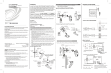
Install into Drop Ceiling or Drywall
1. In the location identified in “Determine the Mounting Location,”
mark the hole for the cutout using a pencil and the hole cutout
template.
2. Cut a hole in the drop ceiling or drywall following the marks made
in Step 1. Use tools appropriate for the surface type.
3. Wire the CEN-ODT-C-POE. Refer to the “Wiring” section for
details.
4. Place the sensor base into the hole and secure it to the drywall or
ceiling tile by tightening the preinstalled screws. Plastic wings are
attached to the preinstalled screws that open when the screws
are tightened to secure the sensor base to the drop ceiling or
drywall.
Drop Ceiling
or Drywall
CEN-ODT-C-POE
(cover removed)
Cover
5. Install the sensor cover. Align the arrows on the sensor cover with
the arrows on the sensor base and then place the sensor cover on
the sensor base. Twist clockwise until the cover clicks into place.
Install Into an Octagon Electrical Box
1. Remove the preinstalled screws and the plastic wings.
Use a slotted or #2 Phillips screwdriver to turn the screw
counterclockwise until the plastic wings are removed and the
screws can be removed.
2. Wire the CEN-ODT-C-POE. Refer to the “Wiring” section for
details.
3. Secure the CEN-ODT-C-POE to the octagon electrical box using
two screws (not supplied). Ensure that the occupancy sensor
faces the correct direction.
Octagon
Electrical Box
CEN-ODT-C-POE
(cover removed)
Mounting Screws
(not supplied)
Cover
4. Install the sensor cover. Align the arrows on the sensor cover with
the arrows on the sensor base and then place the sensor cover on
the sensor base. Twist clockwise until the cover clicks into place.
LED Functions
The CEN-ODT-C-POE has five LEDs.
• Passive Infrared (PIR): Lights red to indicate PIR motion detected.
• Ultrasonic (US): Lights green to indicate US motion detected.
• NET: Lights yellow to indicate no LAN connection to host.
• Power/Firmware: Lights green when the device is operating
normally. Lights yellow if the firmware fails to load.
• Setup: Lights blue to indicate an identify command sent by the
host.
Restart the CEN-ODT-C-POE
Press and hold the SETUP button to restart the CEN-ODT-C-POE. The
power/firmware LED lights yellow while the CEN-ODT-C-POE starts up
and then lights green when the CEN-ODT-C-POE is ready for use.
Configure the CEN-ODT-C-POE
The CEN-ODT-C-POE provides a web configuration interface that is
used to view and configure the CEN-ODT-C-POE. The interface can be
accessed using the IP address of the CEN-ODT-C-POE or the Crestron
XiO Cloud™ service.
NOTE: Use the Device Discovery tool in Crestron Toolbox™ software to
obtain the IP address of the CEN-ODT-C-POE.
The Crestron XiO Cloud service allows supported Crestron devices
across an enterprise to be managed and configured from one central
and secure location in the cloud. Supported devices are configured to
connect to the service. Use of the service requires a registered Crestron
XiO Cloud account.
NOTE: The device may be disconnected from the service by navigating
to the Cloud Services tab in Crestron Toolbox software (Functions >
Device Info > Cloud Services). For details, refer to the Crestron Toolbox
help file.
To access the web configuration interface using the Crestron XiO Cloud
service:
1. Record the MAC address and serial number that are labeled on
the shipping box or rear panel of the device. The MAC address and
serial number are required to add the device to the service.
2. Do either of the following:
• For existing accounts, access the Crestron XiO Cloud service
at https://portal.crestron.io.
• For new accounts, register for a Crestron XiO Cloud account
at www.crestron.com/xio-cloud-registration.
3. Claim the device to the service as described in the Crestron XiO
Cloud User Guide (Doc. 8214) at www.crestron.com/manuals.
4. Select the device from the cloud interface to view its settings.
Test the CEN-ODT-C-POE
Confirm that the sensor operates as intended after installation.
Verify the Detection Range
The red and green LEDs on the CEN-ODT-C-POE should flash only
when they detect motion caused by room occupants. To verify the
motion detection:
1. Enter the room and close all of the doors.
2. Sit in the room and monitor the red and green LEDs on the
CEN-ODT-C-POE. Remain still to prevent the CEN-ODT-C-POE
from detecting your presence in the room.
3. If the red and green LEDs on the CEN-ODT-C-POE flash, the
sensors are detecting unwanted motion. Identify and correct the
sources of motion (projectors, fans, vents, etc.).
Test the Occupancy Sensitivity
NOTE: If multiple occupancy sensors are located in the same room,
adjust one at a time.
1. Walk around the room to simulate typical room motion (e.g., sit at
various places around the room and simulate typical motion for
the room).
2. While walking around the room, monitor the LEDs on the
CEN-ODT-C-POE to verify that the motion is detected. Red
indicates PIR motion and green indicates US motion.
3. If motion in the room is not detected, increase the sensitivity of
the PIR or US sensors.
NOTE: If motion is not detected in the corners of the room,
increase the timeout to allow more time to detect motion.
4. Repeat these steps until all expected motion is detected.
Troubleshoot Symptoms
The following table provides corrective action for possible trouble
situations. If further assistance is required, please contact a Crestron
Customer service representative.
Symptom Issue Action
The lights do
not turn on.
The circuit breaker or
fuse has tripped.
Reset the circuit breaker
or replace the fuse.
The control system
is incorrectly
programmed.
Verify the program in the
control system.
There is a miswire. Verify that the wires are
connected properly.
There are incorrect
settings on the device.
Increase the sensitivity
setting on the PIR sensor,
and then increase the US
sensors.
The mounting location
is incorrect.
Move the sensor into
an area that senses the
occupant or point of
motion.
The lights do
not turn off.
There is constant
motion in the room.
To test, reduce the
sensitivity level and
remove the motion
source. If there is
no change, then the
mounting location must
move.
There is motion
detected in a hallway or
another room.
Put the sensor into Setup
mode and walk by the
area. If the red or green
LED blinks, move the
sensor, mask the PIR, or
disable one side of the
US sensors.
There are incorrect
settings on the device.
Reduce the sensitivity
and timeout levels.
The control system
is incorrectly
programmed.
Verify the program in the
control system.
The lights
remain on for
too long.
The timeout setting is
too high.
Reduce the timeout one
step at a time.
Additional Information
Scan or click the QR code for detailed product information.
CEN-ODT-C-POE
Compliance and Legal
Original Instructions: The U.S. English version of this document is the original instructions. All
other languages are a translation of the original instructions.
Regulatory Model: M2001903001
This product is listed to applicable UL® Standards and requirements tested by Intertek®
services.
Ce produit est homologué selon les normes et les exigences UL applicables par Intertek
Prestations de service.
This product conforms to ANSI/UL® STD 2043 tested by Intertek® services.
The product warranty can be found at www.crestron.com/warranty.
The specific patents that cover Crestron products are listed at
www.crestron.com/legal/patents.
Certain Crestron products contain open source software. For specific information, please
visit www.crestron.com/opensource.
Crestron, the Crestron logo, Crestron Toolbox, and Crestron XiO Cloud are either trademarks
or registered trademarks of Crestron Electronics, Inc. in the United States and/or other
countries. Intertek and the Intertek logo are either trademarks or registered trademarks of
Intertek Group in the United States and/or other countries. The ETL logo is either a trademark
or registered trademark of Intertek Testing Services NA in the United States and/or other
countries. UL is either a trademark or registered trademark of Underwriters Laboratories, Inc.
in the United States and/or other countries. Other trademarks, registered trademarks, and
trade names may be used in this document to refer to either the entities claiming the marks
and names or their products. Crestron disclaims any proprietary interest in the marks and
names of others. Crestron is not responsible for errors in typography or photography.
©2019 Crestron Electronics, Inc.
Crestron Electronics, Inc.
15 Volvo Drive, Rockleigh, NJ 07647
Tel: 888.CRESTRON
Fax: 201.767.7576
www.crestron.com
Quick Start - Doc. 8258A
(2053677)
10/16/19
Specifications subject to
change without notice.
/