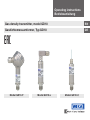
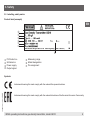
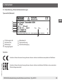
WIKA GD10-C tag:model:GD10-F tag:model:GD10-L Operating instructions
- Type
- Operating instructions

Operating instructions
Betriebsanleitung
EN
DE
Gasdichtemessumformer, Typ GD10
Model GD10-F Model GD10-L Model GD10-C
Gas density transmitter, model GD10

2 WIKA operating instructions gas density transmitter, model GD10
EN
DE
14028479.01 12/2015 EN/DE
© 2015 WIKA Alexander Wiegand SE & Co. KG
All rights reserved. / Alle Rechte vorbehalten.
WIKA
®
is a registered trademark in various countries.
WIKA
®
ist eine geschützte Marke in verschiedenen Ländern.
Prior to starting any work, read the operating instructions!
Keep for later use!
Vor Beginn aller Arbeiten Betriebsanleitung lesen!
Zum späteren Gebrauch aufbewahren!
Betriebsanleitung Typ GD10 Seite 23 - 42
Operating instructions model GD10 Page 3 - 22

EN
3WIKA operating instructions gas density transmitter, model GD10
14028479.01 12/2015 EN/DE
Contents
Contents
1. General information............................................................5
2. Design and function ...........................................................6
2.1 Overview ....................................................................6
2.2 Scope of delivery..............................................................6
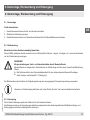
3. Safety........................................................................7
3.1 Explanation of symbols.........................................................7
3.2 Intended use .................................................................7
3.3 Personnel qualification .........................................................8
3.4 Valid standards and guidelines for SF
6
gas.........................................8
3.5 Labelling, safety marks.........................................................9
4. Transport, packaging and storage...............................................10
5. Commissioning, operation .....................................................11
5.1 Mounting the instrument .......................................................11
5.1.1 Requirements for mounting point .........................................11
5.1.2 Sealing variants .......................................................11
5.1.3 Mounting the instrument ................................................12
5.2 Connecting the instrument to the electric system...................................12
5.2.1 Requirements for voltage supply .........................................12
5.2.2 Requirements for electrical connection ....................................12
5.2.3 Requirement for shielding and grounding ..................................12
5.2.4 Connecting the instrument ..............................................13
5.2.5 Testing the output signal (model GD10-F only) ..............................13
5.2.6 Pin assignments.......................................................13

EN
4 WIKA operating instructions gas density transmitter, model GD10
14028479.01 12/2015 EN/DE
6. Faults .......................................................................15
7. Maintenance and cleaning .....................................................16
8. Dismounting, return and disposal ...............................................17
9. Specifications................................................................18
Appendix 1: EC declaration of conformity ...........................................22
Declarations of conformity can be found online at www.wika.com
Contents

EN
5WIKA operating instructions gas density transmitter, model GD10
14028479.01 12/2015 EN/DE
1. General information
1. General information
■
The instrument described in the operating instructions has been designed and manufactured using state-of-the-
art technology. All components are subject to stringent quality and environmental criteria during production. Our
management systems are certied to ISO 9001 and ISO 14001.
■
These operating instructions contain important information on handling the instrument. Working safely requires that
all safety instructions and work instructions are observed.
■
Observe the relevant local accident prevention regulations and general safety regulations for the instrument's range
of use.
■
The operating instructions are part of the product and must be kept in the immediate vicinity of the instrument and
readily accessible to skilled personnel at any time. Pass the operating instructions onto the next operator or owner of
the instrument.
■
Skilled personnel must have carefully read and understood the operating instructions prior to beginning any work.
■
The general terms and conditions contained in the sales documentation shall apply.
■
Subject to technical modications.
■
Further information:
- Internet address: www.wika.de/sf6 / www.wika.com/sf6
- Relevant data sheet: SP 60.10, SP 60.11
- Application consultant:
Tel.: +49 9372 132-8971
Fax: +49 9372 132-8008971

EN
6 WIKA operating instructions gas density transmitter, model GD10
14028479.01 12/2015 EN/DE
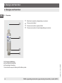
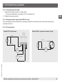
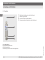
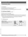
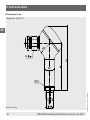
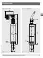
2. Design and function
2. Design and function
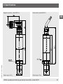
2.1 Overview
Electrical connection (depending on version)
Case; product label
Process connection, spanner ats
Process connection, thread (depending on version)
2.2 Scope of delivery
■
Gas density transmitter
■
Operating instructions
Cross-check scope of delivery with delivery note.

EN
7WIKA operating instructions gas density transmitter, model GD10
14028479.01 12/2015 EN/DE
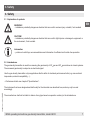
3. Safety
3. Safety
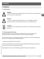
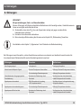
3.1 Explanation of symbols
WARNING!
... indicates a potentially dangerous situation that can result in serious injury or death, if not avoided.
CAUTION!
... indicates a potentially dangerous situation that can result in light injuries or damage to equipment or
the environment, if not avoided.
Information
... points out useful tips, recommendations and information for ecient and trouble-free operation.
3.2 Intended use
The gas density transmitter is used for measuring the gas density of SF
6
gas and SF
6
gas mixtures in closed systems.
The measured gas density is output as an electrical signal.
Use the gas density transmitter only in applications that lie within its technical performance limits (e.g. max. ambient
temperature, material compatibility, ...).
→ Performance limits see chapter 9 “Specications”.
The instrument has been designed and built solely for the intended use described here, and may only be used
accordingly.
The manufacturer shall not be liable for claims of any type based on operation contrary to the intended use.

EN
8 WIKA operating instructions gas density transmitter, model GD10
14028479.01 12/2015 EN/DE
3.3 Personnel qualication
Skilled personnel
Skilled personnel, authorised by the operator, are understood to be personnel who, based on their technical training,
knowledge of measurement and control technology and on their experience and knowledge of country-specic
regulations, current standards and directives, are capable of carrying out the work described and independently
recognising potential hazards.
The plant operator must ensure that the handling of SF
6
gas is only carried out by a qualied company or by qualied
persons who have been specially trained in accordance with IEC 61634, section 4.3.1 or IEC 60480, section 10.3.1.
3.4 Valid standards and guidelines for SF
6
gas
Installation, assembly, commissioning:
■
BGI 753 (SF
6
plants and equipment in Germany)
■
IEC 61634 (Handling of SF
6
gas)
■
IEC 60376 (New SF
6
gas, technical grade SF
6
gas)
■
IEC 60480 (Used SF
6
gas)
■
CIGRE report 276, 2005 (Practical SF
6
gas handling instructions)
Leaks during operation:
■
IEC 60376 (New SF
6
gas, technical grade SF
6
gas)
■
IEC 60480 (Used SF
6
gas)
■
CIGRE 2002 (SF
6
gas in the electrical industry)
Repair work and maintenance:
■
IEC 61634 (Use and handling of SF
6
gas in high-voltage switchgear and controlgear)
■
CIGRE 1991 (Handling of SF
6
gas)
■
CIGRE report 276, 2005 (Practical SF
6
gas handling instructions)
■
CIGRE report 163, 2000 (Guide for SF
6
gas mixtures)
SF
6
is a colourless and odourless, chemically neutral, inert and non-ammable gas which is approx. ve times heavier
than air, non-toxic and not harmful to the ozone layer. Detailed information is given in IEC 60376 and IEC 61634.
3. Safety

EN
9WIKA operating instructions gas density transmitter, model GD10
14028479.01 12/2015 EN/DE
3. Safety
3.5 Labelling, safety marks
Product label (example)
P# Product no.
Measuring range
S# Serial no.
Model designation
Power supply
Pin assignment
Output signal
Symbols
Instruments bearing this mark comply with the relevant European directives.
Instruments bearing this mark comply with the relevant directives of the Eurasian Economic Community.

EN
10 WIKA operating instructions gas density transmitter, model GD10
14028479.01 12/2015 EN/DE
4. Transport, packaging and storage
4. Transport, packaging and storage
4.1 Transport
Check the gas density transmitter for any damage that may have been caused by transport.
Obvious damage must be reported immediately.
4.2 Packaging and storage
Do not remove packaging until just before mounting.
Keep the packaging as it will provide optimum protection during transport (e.g. change in installation site, sending for
repair).
Permissible conditions at the place of storage:
■
Storage temperature: -40 ... +80 °C
■
Humidity: 45 ... 75 % relative humidity (no condensation)

EN
11WIKA operating instructions gas density transmitter, model GD10
14028479.01 12/2015 EN/DE
5. Commissioning, operation
5. Commissioning, operation
5.1 Mounting the instrument
Prior to commissioning, subject the gas density transmitter to a visual inspection.
■
Leaking uid is indicative of damage.
■
Use the gas density transmitter only if it is in perfect condition with respect to safety.
5.1.1 Requirements for mounting point
The mounting point must meet the following conditions:
■
Sealing faces are clean and undamaged.
■
Sucient space for a safe electrical installation.
■
For information on tapped holes and welding sockets, see Technical information IN 00.14 at www.wika.com.
■
Permissible ambient and medium temperatures remain within the performance limits. Consider possible restrictions
on the ambient temperature range caused by mating connector used.
→ For the performance limits, see chapter 9 “Specications”
5.1.2 Sealing variants
Parallel threads
Seal the sealing face with a flat gasket, lens-type
sealing ring or WIKA profile sealing.
per EN 837
per DIN 3852-E

EN
12 WIKA operating instructions gas density transmitter, model GD10
14028479.01 12/2015 EN/DE
5.1.3 Mounting the instrument
The max. torque depends on the mounting point (e.g. material and shape). If you have any questions,
please contact our application consultant.
→ For contact details, please see chapter 1 “General information” or the back page of the operating
instructions.
1. Seal the sealing face (→ see chapter 5.1.2 “Sealing variants”).
2
.
Screw the gas density transmitter into the mounting point by hand.
3
.
Tighten with a torque spanner using the spanner ats.
5.2 Connecting the instrument to the electric system
5.2.1 Requirements for voltage supply
Power supply: DC 10 ... 30 V
The gas density transmitter must be supplied with power by an energy-limited circuit in accordance with IEC 61010-1.
5.2.2 Requirements for electrical connection
■
Cable diameter matches the cable bushing of the mating connector.
■
Cable gland and seals of the mating connector are correctly seated.
■
With cable outlets, no humidity can ingress at the cable end.
5.2.3 Requirement for shielding and grounding
The gas density transmitter must be shielded and grounded in accordance with the grounding concept of the plant.
Model GD10-F, eld case
Terminal 5 is connected to the case, allowing a cable shield to be attached. No specic ground connector is required.
5. Commissioning, operation

EN
13WIKA operating instructions gas density transmitter, model GD10
14028479.01 12/2015 EN/DE
5.2.4 Connecting the instrument
1. Assemble the mating connector or cable outlet.
→ For the pin assignments, see chapter 5.2.6 “Pin assignments”.
2
.
Establish the plug connection.
5.2.5 Testing the output signal (model GD10-F only)
The output signal can be measured by connecting an ammeter to terminals 3 and 4 without disconnecting the
measurement circuit.
5.2.6 Pin assignments
Model GD10-L, angular connector (2-pin)Model GD10-F, eld case
+
-
U
A
UB+/Sig+
0V/Sig-
A
RI ≤ 20Ω
Test+
Test-
+
-
U
A
UB+/Sig+
0V/Sig-
5. Commissioning, operation

EN
14 WIKA operating instructions gas density transmitter, model GD10
14028479.01 12/2015 EN/DE
Model GD10-L, cable outlet
+
-
U
UB+/Sig+
0V/Sig-
A
BN
GN
5. Commissioning, operation

EN
15WIKA operating instructions gas density transmitter, model GD10
14028479.01 12/2015 EN/DE
6. Faults
6. Faults
CAUTION!
Physical injuries and damage to property and the environment
If faults cannot be eliminated by means of the measures listed, the gas density transmitter must be shut
down immediately.
▶
Ensure that no more SF
6
or signal is applied and protect the transmitter against being put into
operation accidentally.
▶
Contact the manufacturer.
▶
If a return is needed, please follow the instructions given in chapter 8.2 “Return”.
For contact details, please see chapter 1 “General information” or the back page of the operating
instructions.
In the event of any faults, rst check whether the gas density transmitter has been mounted correctly, mechanically and
electrically.
If complaint is unjustied, the handling costs will be charged.
Faults Causes Measures
No output signal Cable break Check the continuity
Deviating zero point signal Overpressure limit exceeded Observe the permissible overpressure limit
Too high/low working temperature Observe the permissible temperatures
Constant output signal upon change in
pressure
Mechanical overload caused by overpres-
sure
Replace instrument; if it fails repeatedly,
contact the manufacturer
Signal span varies EMC interference sources in the environ-
ment; for example, frequency converter
Shield instrument; cable shield; remove
source of interference
Signal span varies/inaccurate Too high/low working temperature Observe the permissible temperatures
Signal span drops/too small Mechanical overload caused by overpres-
sure
Replace instrument; if it fails repeatedly,
contact the manufacturer

EN
16 WIKA operating instructions gas density transmitter, model GD10
14028479.01 12/2015 EN/DE
7. Maintenance and cleaning
7. Maintenance and cleaning
7.1 Maintenance
This gas density transmitter is maintenance-free.
Repairs must only be carried out by the manufacturer.
7.2 Cleaning
CAUTION!
Unsuitable cleaning agents
Cleaning with unsuitable cleaning agents may damage the instrument and the product label.
▶
Do not use any aggressive cleaning agents.
▶
Do not use any hard or pointed objects.
▶
Do not use any abrasive cloths or sponges.
Suitable cleaning agents
■
Water
■
Conventional dishwashing detergent
Cleaning the instrument
1. Depressurise and de-energise the gas density transmitter.
2. Wipe the instrument surface using a soft, damp cloth.

EN
17WIKA operating instructions gas density transmitter, model GD10
14028479.01 12/2015 EN/DE
8. Dismounting, return and disposal
8. Dismounting, return and disposal
8.1 Dismounting
Dismounting the instrument
1. Depressurise and de-energise the gas density transmitter.
2
.
Disconnect the electrical connection.
3
.
Unscrew the gas density transmitter with a spanner using the spanner ats.
8.2 Return
Strictly observe the following when shipping the instrument:
All instruments delivered to WIKA must be free from any kind of hazardous substances (acids, bases, solutions, etc.)
and must therefore be cleaned before being returned.
WARNING!
Physical injuries and damage to property and the environment through residual media
Residual media in the dismounted instrument can result in a risk to persons, the environment and
equipment.
▶
With hazardous substances, include the material safety data sheet for the corresponding medium.
▶
Clean the instrument, see chapter 7.2 “Cleaning”.
When returning the instrument, use the original packaging or a suitable transport package.
Information on returns can be found under the heading “Service” on our local website.
8.3 Disposal
Incorrect disposal can put the environment at risk.
Dispose of instrument components and packaging materials in an environmentally compatible way and in accordance
with the country-specic waste disposal regulations.

EN
18 WIKA operating instructions gas density transmitter, model GD10
14028479.01 12/2015 EN/DE
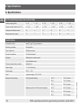
9. Specications
For the measuring ranges (see product label)
Density range (g/litre) 0 ... 10 0 ... 16 0 ... 25 0 ... 40 0 ... 60 0 ... 80
Pressure range (based on 20 °C) 0 ... 1.64 0 ... 2.59 0 ... 3.97 0 ... 6.16 0 ... 8.87 0 ... 11.33
Overpressure limit (bar abs.) 14 14 14 29 29 67
Burst pressure (bar abs.) 17 17 17 35 35 80
Specications
Permissible media pure SF
6
gas, SF
6
gas mixtures
Measuring principle Piezoresistive
Type of pressure Absolute pressure
Process connection G ½ B male thread
Materials Wetted parts: stainless steel
Case: Stainless steel
Pressure transmission medium Synthetic oil
Output signal 4 ... 20 mA (2-wire)
Power supply DC 10 ... 30 V
Load ≤ (power supply - 8 V) / 0.02 A
Measurement accuracy Point of optimal density -40 °C 3.0 % of span
20 °C 1.0 % of span
60 °C 2.3 % of span
Beginning and end of the measuring range -40 °C 4.0 % of span
20 °C 2.0 % of span
60 °C 3.3 % of span
9. Specications

EN
19WIKA operating instructions gas density transmitter, model GD10
14028479.01 12/2015 EN/DE
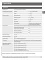
Specications
Stability per year ≤ 0.3 % of span (at reference conditions)
Permissible ambient temperature Operation -40 ... + 60 °C (gaseous phase)
Storage -40 ... +80 °C
Reference conditions Ambient temperature 15 ... 25 °C
Atmospheric pressure 860 ... 1,060 mbar
Humidity 45 ... 75 % r. h.
Power supply DC 24 V
Mounting position Calibrated in vertical mounting position with
pressure connection facing downwards.
Ingress protection The stated ingress protection only applies when plugged in using mating connectors that have
the appropriate ingress protection.
Angular connector, model GD10-L IP67
Field case, model GD10-F IP67
Cable outlet model GD10-C IP68
Short-circuit resistance S+ vs. 0V
Reverse polarity protection U
B
vs. 0V
Insulation voltage DC 750 V, electrical connection vs. case
CE conformity EMC directive 2004/108/EC EN 61326 emission (group 1, class B) and interference immunity
(industrial application)
Electromagnetic compatibility
(EMC) to IEC 61000-4
IEC 61000-4-2 (ESD): test level 4 (8 kV)
IEC 61000-4-3 (Field): test level 3 (10 V/m)
IEC 61000-4-4 (Burst): test level X (±2 kV)
IEC 61000-4-5 (Surge): test level 2 (±1 kV)
IEC 61000-4-6 (Conducted RFI): test level 3 (10 V)
For further specications, see WIKA data sheets SP 60.10, SP 60.11 and the order documentation.
9. Specications

EN
20 WIKA operating instructions gas density transmitter, model GD10
14028479.01 12/2015 EN/DE
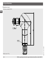
Dimensions in mm
Field case, model GD10-F
Weight: approx. 500 g
9. Specications
Page is loading ...
Page is loading ...
Page is loading ...
Page is loading ...
Page is loading ...
Page is loading ...
Page is loading ...
Page is loading ...
Page is loading ...
Page is loading ...
Page is loading ...
Page is loading ...
Page is loading ...
Page is loading ...
Page is loading ...
Page is loading ...
Page is loading ...
Page is loading ...
Page is loading ...
Page is loading ...
Page is loading ...
Page is loading ...
Page is loading ...
Page is loading ...
-
 1
1
-
 2
2
-
 3
3
-
 4
4
-
 5
5
-
 6
6
-
 7
7
-
 8
8
-
 9
9
-
 10
10
-
 11
11
-
 12
12
-
 13
13
-
 14
14
-
 15
15
-
 16
16
-
 17
17
-
 18
18
-
 19
19
-
 20
20
-
 21
21
-
 22
22
-
 23
23
-
 24
24
-
 25
25
-
 26
26
-
 27
27
-
 28
28
-
 29
29
-
 30
30
-
 31
31
-
 32
32
-
 33
33
-
 34
34
-
 35
35
-
 36
36
-
 37
37
-
 38
38
-
 39
39
-
 40
40
-
 41
41
-
 42
42
-
 43
43
-
 44
44


WIKA GD10-C tag:model:GD10-F tag:model:GD10-L Operating instructions
- Type
- Operating instructions
Ask a question and I''ll find the answer in the document
Finding information in a document is now easier with AI
in other languages
Related papers
-
WIKA GFU08-B tag:model:GFU08-C tag:model:GFU08-E tag:model:GFU08-W Operating instructions
-
-
-
-
-
-
-
-
-
Other documents
-
Eaton COOPER POWER SERIES Operating instructions
-
 Nilfisk-Advance America CFM GD10 User manual
-
 Ion Science SF6 AreaCheck P2 fixed leak detector User manual
-
SICK TBT Resistance thermometers Operating instructions
-
 RH Systems 973-SF6 Owner's manual
-
 RH Systems 973-SF6ABB Owner's manual
-
-
-
-
iON SF6 P2 User manual


