Page is loading ...

Operating Manual
VoluDrop Dispenser UV
97650

2
Contents
English....................................................................................................................3 - 16

3
Contents
1 Please observe the following......................................................................................4
1.1 Emphasized Sections.....................................................................................................4
1.2 Items Supplied................................................................................................................4
1.3 For Your Safety..............................................................................................................5
1.4 Field of Application (Intended Usage)............................................................................5
2 Description....................................................................................................................6
2.1 Theory of Operation .......................................................................................................6
2.2 Operating Elements and Connections............................................................................6
3 Technical Data..............................................................................................................7
4 Installation ....................................................................................................................8
4.1 Connecting to the Product Reservoir .............................................................................8
4.2 Connecting to the Controller...........................................................................................8
4.3 Selection of the Required Dispensing Needle..............................................................10
5 Dispensing..................................................................................................................11
5.1 Flushing........................................................................................................................11
5.2 Adjusting the Dispensing Quantity ...............................................................................12
5.3 Shutdown .....................................................................................................................12
5.4 Returning to Operation.................................................................................................12
6 Maintenance................................................................................................................13
7 Troubleshooting.........................................................................................................14
8 Annex ..........................................................................................................................15
8.1 Accessories and Spare Parts.......................................................................................15
8.2 Manufacturer’s Declaration ..........................................................................................16
8.3 Warranty (excluding Germany) ....................................................................................16

4
1 Please observe the following
1.1 Emphasized Sections
Warning!
Refers to safety regulations and requires safety measures that protect the operator or
other persons from injury or danger to life.
Caution!
Emphasizes what must be done or avoided so that the unit or other property is not
damaged.
Notice
Gives recommendations for better handling of the unit during operation or adjustment as
well as for service activities.
The numbers printed in bold in the text refer to the corresponding position numbers in
the illustration on page 7.
• The point emphasizes an instruction
step.
Instruction steps in the illustrations are
indicated with arrows.
When several instruction steps are
indicated in an illustration, the shading of
the arrow has the following meaning:
Black arrow = 1
st
step
Grey arrow = 2
nd
step
White arrow = 3
rd
step
1.2 Items Supplied
– 1 VoluDrop Dispenser 97650
– 1 Needle Variety Kit 97262;
– 1 Product Feedline, length 2 m, including Valve Fitting ¼”
– 1 Instruction Manual 97650
– 1 Assembly Tool for Maintenance
– 1 Air Pressure Hose OD 4 mm calibrated, length 1 m
As a result of technical development, the illustrations and descriptions in this operating
manual can deviate in detail from the actual unit delivered.

5
1 Please observe the following
1.3 For Your Safety
For safe and successful operation of the unit, read these instructions completely.
If the instructions are not observed, the manufacturer can assume no responsibility.
Be sure to retain this manual for future reference.
When working with pressurized air, wear protective glasses!
Observe general safety regulations and manufacturer’s instructions for the
handling of chemicals.
If chemical products are not properly handled, damage to health can result!
Request a safety data sheet for the LOCTITE
®
-adhesive used!
1.4 Field of Application (Intended Usage)
The VoluDrop Dispenser is suitable only for the exact drop application of
LOCTITE UV acrylics up to a viscosity of 15,000 mPas.
It is not suitable to dispense UV acrylics with anaerobic component,
cyanoacrylates, abrasive adhesives and anaerobics.
Only drop dispensing is possible.
Up to a viscosity of 5,000 mPas the dispenser is able to spit adhesives.
Spitting is possible form 3 µl up to 15 µl, non-spitting from 0.8 µl up to 3 µl.
Within a distance of 50 mm a feed motion of the workpiece is not necessary. The
dispenser should be mounted with the dispensing needle downwards.
The dispenser is used as a stationary applicator unit. It is mounted directly at the
dispensing position. The free end of the product feedline is connected to the product
reservoir.
For product reservoirs, 0.5 l and 2 l versions are available.
The control of the dispenser is provided by a control unit of the LOCTITE equipment line.

6
2 Description
2.1 Theory of Operation
The LOCTITE adhesive is transported through a product feedline to the dispenser by the
dispensing pressure in the product reservoir. This feedline has a PTFE-liner to prevent
curing of adhesives in this area.
When the ejector piston moves back the dispensing chamber will be filled. The adhesive
is spat under high pressure by very fast movement of the piston. During dispensing a
non-return valve prevents back-flow of adhesive to the reservoir.
The amount of product dispensed is controlled by the volume of the dispensing chamber.
Via a stroke adjustment the amount can be limited between 0.8 µl to 15 µl per shot.
As a matter of principle, spitting is possible with each LOCTITE dispensing needle. An
exact spitting is only possible with the conical needles.
Generally, the size of the needle should be adapted to the required amount.
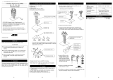
2.2 Operating Elements and Connections
1
Luer-Lock Adapter to mount a dispensing needle.
2
Integrated Non-Return Valve prevents dripping of adhesive due to the
reservoir pressure.
3
Non-Return Valve to prevent back-flow of adhesive to the reservoir during
dispensing.
4
Feedline Connector to connect a feedline (OD 1/4" or 6 mm) to the reservoir.
5
Dispenser
6
Lock Nut to fix the stroke adjustment knob.
7
Stroke Adjustment Knob to reduce stroke and therewith the dispensed
quantity.
8
Compressed Air Connector, to connect pneumatic tube, OD see section 3.
9
Assembly Tool for maintenance, see section 6
13457
8
6
2
9

7
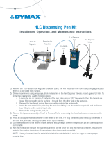
3 Technical Data
Pneumatic supply min. 6 bar (87 psi)
Quality
If required quality is not achieved, install a
LOCTITE filter regulator
Filtered 10 µm, oil-free, non-condensing
Accessory Order No. 97120
Pneumatic hose size, control air
connection
External dia. 4 mm calibrated;
Internal dia. 2.5 mm
Dispensing Rate 4 shot/s, depends on viscosity of adhesive,
in continuous mode up to 15 µl.
Product Feedline Standard: ¼” OD, or 6 mm OD
Reservoir Pressure 0.6 bar (8.7 psi) - 0.8 bar (11.6 psi)
Flushing Pressure > 7 bar (100 psi) < 8 bar (116 psi)
Weight 260 g
25.5 mm
1"
52 mm
1.05"
26.5 mm
1.04"
71 mm
2.8"
2 mm
0.08"
~162.5 mm
~6.4"
20 mm
0.78"
42 mm
1.65"
35 mm
1.38"
8.5 mm
0.33"
M4, depth 5 mm (0.2")
Clamping
Area
42.5 mm
16.7 "

8
4 Installation
– Keep the pressure hose as short as possible. Short switch-on and switch-off times for
the dispenser are within reach.
– Keep product feedlines as short as possible. The shorter the feedline the smaller the
specific resistance and the lower the dispensing pressure can be.
– Avoid kinking of feedlines and pressure hoses.
– Typically, the pressure hose and product feedline should not be longer than 2 m.
– Do not use inflexible hoses and feedlines, so that unnecessary loads on the fittings will
be avoided.
– Keep all fittings tight.
– No direct sunlight; no UV light!
4.1 Connecting to the Product Reservoir
4.2 Connecting to the Controller
97102
R
0.5 ltr.: length 200 mm
2 ltr.: length 275 mm
90–260 VAC/47–63 Hz
2 AM
XS1
XS1: Start
XS2: Reservoir
Loctite (Ireland) Ltd.
Made in Germany
cat.no.97102
XS2
8900102

9
4 Installation
97103/97204
97123
97009
AB
85–264 VAC/50–440 Hz
2 AM
XS1: Start
XS2: Reservoir
XS3: Turntable
XS4: DC Motor
XS5: Monitor A
XS6: Monitor B
XS7: RS232 Master
XS8: RS232 Slave
XS9: PLC Interface
XS10: I/O port
XS11: Servo A/B
XS12: Channel A/B
Loctite (Ireland) Ltd.
Ma
d
e
i
n
Ge
rm
a
n
y
cat.no.97103
XS1 XS2
XS3
XS4
XS5
XS12 XS11 XS10 XS9
XS6
XS7
XS8
O
I
O
I
Coax
Coax
O
I
9
0-26
0
V
AC
4
7
-6
3
H
z
P
ha
se
= 1
X
S
1
S
t
a
r
t
X
S
2
R
e
s
e
r
v
o
ir
X
S
3
F
lo
w
M
o
n
it
o
r
X
S
5
P
L
C
In
t
e
r
f
a
c
e
X
S
4
R
S
2
3
2
2 A
M
cat. no. 97123
L
o
c
t
i
t
e
(
I
r
e
l
a
n
d
)
L
t
d
.
T
a
l
l
a
g
h
t
B
u
s
i
n
e
s
s
P
a
r
k
W
h
i
t
e
s
t
o
w
n
T
a
l
la
g
h
t
,
D
u
b
l
i
n
2
4
,
I
r
e
l
a
n
d
M
a
d
e
i
n
G
e
r
m
a
n
y
P
o
w
e
r
c
o
n
s
u
m
p
t
i
o
n
m
a
x
.
6
0
W
X
S
6
X
S
7
X
S
8
A
B
P
i
n
6
-
8
b
a
r
0
1
O
I
R
8
8
8
CONT
CONT
2
0
30
60
90
120
6
8
10
psi
bar
I
0

10
4 Installation
4.3 Selection of the Required Dispensing Needle
For each product and corresponding application of the
dispenser, various dispensing
needle types and sizes are available:
– Conical dispensing needles of polyethylene for viscous products and large
dispensed quantities.
– Stainless steel needles for thin fluids and UV curing products (especially suitable
for spot applications).
– Flexible dispensing needles of polypropylene (especially for dispensing on
damageable surfaces).
– PTFE-lined stainless steel needles (especially for fast curing products).
As a matter of principle, spitting is possible with each LOCTITE dispensing needle.
An exact spitting is only possible with the conical dispensing needles.
With same dispensing quantity certain correlation determines the selection of the
needle.
The table below shows these correlation.
Dispensing Needle
Pressure Loss
along the Needle
Risk of Dripping Spitting
Conical
dispensing
needles PE
97221 – 97224
small small possible
Stainless Steel
needle SSS
97225 - 97228
Flexible
dispensing
needles PP
97229 – 97232
high
high
not possible
Important for spitting applications:
- conical needles are recommended
- smallest dispense volume is about 3 µl
- inner needle diameter must be adapted to the product viscosity

11
5 Dispensing
5.1 Flushing
To avoid troubles caused by air bubble the product feedline and the VoluDrop Dispenser
must be filled and then purged of air.
Generally, flushing has to be done for the initial startup and also, depending on the
adhesive, in regularly time lags.
Air bubbles can result in the following troubles:
– no or too little product or
– dispenser does not spit.
For easier handling an external possibility of switching between the reservoir pressure
and the necessary flushing pressure should be implemented. It consists of 1 manual
actuated switch-over valves (5/2-way valves, button actuated, fumbling, not resting) and
a connection to the pressure supply of more than 7 bar (100 psi).
See also pneumatic diagram section 8.
The 5/2-way valve is used as a switch-over valve for switching between the
product pressure (reservoir pressure 0.6 - 0.8 bar / 8.7 - 11.6 psi) and the
flushing pressure min. 7 bar (100 psi), max. 8 bar (116 psi).
Basic position of the switch-over valve is in position
reservoir pressure from the controller 0.6 - 0.8 bar.
A compressed air pressure of 7 - 8 bar (100 - 116 psi) is necessary to override the
integrated non-return valve 2. If it is not available an additionally pressure multiplicator
has to be used. To limit the pressure at 8 bar a LOCTITE filter regulator order no. 97120
or a comparable one is necessary. Otherwise the integrated burst plate of the reservoir
can burst (lower burst limit 8.8 bar / 125 psi).
Flushing Procedure
• Mount the components according to the graphic below.
Place a container under the dispenser. Product will flow out!
• Press switch-over valve and keep it pressed. The reservoir will be pressurized
with min. 7 bar.
• Start dispensing for several times.
• Switch over to 0.6 – 0.8 bar by releasing the valve.
• The reservoir will be vented due to the pressure regulator of the controller.
• Wait a short time till the correct pressure 0.6 – 0.8 bar is present.
Dispensing can be continued.
Switch-over
Valve
min. 7 bar (100 psi)
max. 8 bar (116 psi)
0.6 - 0.8 bar
(8.7 - 11.6 psi)
Feedline
Reservoir
Controller
97120
I
0
5
1
2
3
4

12
5 Dispensing
5.2 Adjusting the Dispensing Quantity
The dispensed quantity is adjusted by setting the size of the dispensing chamber in the
dispenser.
• Adjust the required amount of adhesive
by turning the stroke adjustment knob 7
clockwise or counter-clockwise to
decrease or increase the effective size
of the chamber.
• Start dispensing to check the dispensed
amount.
• Go further with this procedure till the
amount is reached.
• Protect the adjustment with the
lock nut 6.
5.3 Shutdown
For short idle periods, 24 hours or less, the system can be left idle without any special
preparations.
It is necessary to change the dispensing needle against the luer-lock tip cap to prevent
curing of the adhesive.
For periods 1 week or longer remove the adhesive from the reservoir and purge the
system with fresh acetone to clear feedline, dispenser and fittings of adhesive.
5.4 Returning to Operation
• Insert product bottle into the reservoir.
• Possibly replace the Luer-Lock tip cap with a new dispensing needle.
• Purge the Dispenser until product runs out bubble free out of it, see section 5.1.
?
Check the adjustment of the dispensing quantity according to of the operating manual of
the used controller.
+
-

13
6 Maintenance
The VoluDrop Dispenser requires no special care.
As maintenance only a sealing ring inside has to be replaced regularly.
The dispenser has to be cleaned, if it is dismantled for replacing the sealing rings, see
section 5.1.
? The maintenance interval is at a
dispensing rate of :
– 10 shots/minute (smallest amount)
every 7 days.
– 4 shots/minute (biggest amount)
every 2-3 weeks.
• Dismantle the dispenser according to
the right graphic.
The number 9 shows the supplied
assembly tool for maintenance.
?
• Unscrew thread disk D with the help of a
screwdriver.
• Remove the shim rings E and keep
them ready
• Use the assembly tool 9 to dismantle
the gasket C and the sealing ring B.
• Replace the sealing ring E.
• Replace the gasket C and the sealing
ring B and mount the new one’s with the
help of the assembly tool 9.
9
X
Y
Z
9
B
C
D
E
9
B
C

14
6 Maintenance
?
• Mount the preassembled gasket/ assembly tool
B
C 9 together with two shim rings E to the shut-off
assembly Y without removing the ass. tool 9.
• Screw thread disk D with the help of a
screwdriver into the shut-off assembly.
• In order to check the thightness of the gasket C
check the mobility of the assembly tool 9. The
gasket must keep the ass. tool in place, but the
ass. tool must be smooth running.
• If the gasket is too tight then remove a shim ring.
Repeat this until the ass. tool is smooth running.
• If the gasket is too loose then add a shim ring.
Repeat this until the ass. tool is smooth running.
• Mount the actuator X to the preassembled shut-
off assembly. The ass. tool 9 will be pressed out.
• Remove the assembly tool 9.
• Wrap a PTFE sealing tape round the thread F of
the integrated non-return valve Z.
• Mount the non-return valve to the shut-off
assembly.
7 Troubleshooting
Type of malfunction Possible causes Correction
No liquid flow or too little
flow.
– Product feedline and/or pneumatic
hose not connected correctly or
kinked.
• Connect the product feedline
correctly. If kinked, replace it.
– Control pressure not adequate.
Control pressure must be
min. 6 bar.
• Check and adjust the control
pressure.
– Curing in the product feedline or in
the dispensing needle.
• Replace the product feedline and/or
the dispensing needle.
– Curing in the VoluDrop Dispenser.
• Loctite Service
– Controller incorrectly adjusted.
• Check the controller setting (see
operating manual of the controller).
– Product reservoir not switched on,
depressurized or pressure is too
low.
• Check the reservoir (see operating
manual of the product reservoir).
– Piston stroke set too small or to 0.
• Turn the adjustment knob 7 anti-
clockwise.
Product drips after
dispensing, eventually
stopping
– Air is trapped in the Dispenser
and/or in the product feedline
and/or in the dispensing needle
• Purge the product feedline,
dispenser and dispensing needle of
air (section 5.1).
VoluDrop Dispenser does
not open.
– Actuator of the dispenser is
contaminated with product.
• Loctite Service
Air bubbles in the product
being dispensed.
– Compressed air being dissolved
into the product.
• Purge the product feedline,
dispenser and dispensing needle of
air (section 5.1). If possible, reduce
the product pressure.
B, C, 9
D
X
Y
Z
F

15
8 Annex
8.1 Accessories and Spare Parts
Also see the illustration on page 7.
Pos.
No.
Description Loctite Order No.
1 Luer-Lock-Adapter Kit................................................................
.
......................97233
2 Integrated Non-return Valve 6 bar.....................................................................8964738
3 Non-return Valve 0.4 bar................................................................
.
..................8964737
Sealing Rings Repair Kit ................................................................
.
..................8964709
– Reservoir Fitting ¼” * ⅛” ................................................................
.
..................8900064
– Product Fitting, SO 31121-6-1/8 PA, Serto jacob GmbH, 34277 Fuldabrück ...–
– Tubing, PTFE-lined, OD ¼”, length 10 m................................
.
.........................97972
– Dispense Needle, Polyethylene – Conical (PPC),
especially for viscous products and large dispensing quantities:
Dispense Needle PPC16GA (50 pcs/box), ID Size 1.19 mm, grey
.
..................
Dispense Needle PPC18GA (50 pcs/box), ID Size 0.84 mm, green
.
................
Dispense Needle PPC20GA (50 pcs/box), ID Size 0.58 mm, pink
.
..................
Dispense Needle PPC22GA (50 pcs/box), ID Size 0.41 mm, blue
.
..................
97221
97222
97223
97224
– Dispense Needle, Stainless Steel – Standard (SSS),
especially for low viscosity and UV curing products:
Dispense Needle SSS15GA (50 pcs/box), ID Size 1.35 mm, amber
.
...............
Dispense Needle SSS18GA (50 pcs/box), ID Size 0.84 mm, green
.
................
Dispense Needle SSS20GA (50 pcs/box), ID Size 0.58 mm, pink
.
..................
Dispense Needle SSS25GA (50 pcs/box), ID Size 0.25 mm, red
.
....................
97225
97226
97227
97228
– Dispense Needle, Polypropylene – Flexible (PPF),
especially for fast curing products:
Dispense Needle PPF15GA (50 pcs/box), ID Size 1.24 mm, amber
.
...............
Dispense Needle PPF18GA (50 pcs/box), ID Size 0.81 mm, green
.
................
Dispense Needle PPF20GA (50 pcs/box), ID Size 0.48 mm, pink
.
..................
Dispense Needle PPF25GA (50 pcs/box), ID Size 0.36 mm, red
.
....................
97229
97230
97231
97232
– Dispense Needle, Stainless Steel – PTFE-lined (SSTL),
especially for fast curing products:
Dispense Needle SSTL25GA (50 pcs/box), ID Size 0.15 mm, pink
.
.................
97238
– Luer-Lock Tip Caps ................................................................
.
.........................97248
– Sealing Ring G1/8”, O-1/8, Festo AG................................
.
...............................–

16
8 Annex
8.2 Manufacturer’s Declaration
The Manufacturer
according to the EC
regulations
Henkel Loctite Deutschland GmbH
Arabellastraße 17
D-81925 München
declares that the unit designated in the following is, as a result of its design and
construction, in accordance with the European regulations, harmonized standards and
national standards listed below.
Designation of the unit VoluDrop Dispenser UV
Unit number 97650
Applicable EC Regulations EC-Machine Directive 98/37/EEC
Applicable harmonized
standards
DIN EN 292 Part 1; DIN EN 292 Part 2 11.1991
Date / Manufacturer’s signature
12/06/2002
Information regarding the Signer General Manager (F. Löhr)
For changes to the unit that were not approved by Loctite, this declaration loses
its validity.
8.3 Warranty (excluding Germany)
Loctite expressly warrants that all products referred to in this Operating Manual under VoluDrop Dispenser
97650 (hereafter called “Products”) shall be free from defects in materials and workmanship. Loctite’s liability
shall be limited, at its option, to replacing those Products which are shown to be defective either in materials
or workmanship or to credit to the purchaser the amount of the purchase price thereof (plus freight and
insurance charges paid therefore by the user). The purchaser’s sole and exclusive remedy for breach or
warranty shall be such replacement or credit. A claim of defect in materials or workmanship in any Products
shall be allowed only when it is submitted to Loctite in writing within one month after discovery of the defect
or after the time the defect should reasonably have been discovered [and in any event within six months
after the delivery of the Products to the purchaser]. No such claim shall be allowed in respect of Products
which have been neglected or improperly stored, transported, handled, installed, connected, operated, used
or maintained or in the event of unauthorized modification or the Products [including, where products, parts
or attachments for use in connection with the Products are available from Loctite, the use of products, parts
or attachments which are not manufactured by Loctite.]
No Products shall be returned to Loctite for any reason without Loctite’s prior written approval. Products shall
be returned freight prepaid, in accordance with Loctite’s instructions.
EXCEPT FOR THE EXPRESS WARRANTY CONTAINED IN THIS SECTION, LOCTITE MAKES NO
WARRANTY OF ANY KIND WHATSOEVER, EXPRESS OR IMPLIED, WITH RESPECT TO THE
PRODUCTS.
ALL WARRANTIES OF MERCHANTABILITY, FITNESS FOR A PARTICULAR PURPOSE, AND OTHER
WARRANTIES OF WHATEVER KIND (INCLUDING AGAINST PATENT OR TRADEMARK
INFRINGEMENT) ARE HEREBY DISCLAIMED BY LOCTITE AND WAIVED BY THE PURCHASER.
THIS SECTION SETS FORTH EXCLUSIVELY ALL OF LOCTITE’S LIABILITY TO THE PURCHASER IN
CONTRACT, IN PART OR OTHERWISE IN THE EVENT OF DEFECTIVE PRODUCTS.
WITHOUT LIMITATION OF THE FOREGOING, TO THE FULLEST EXTENT POSSIBLE UNDER
APPLICABLE LAWS, LOCTITE EXPRESSLY DISCLAIMS ANY LIABILITY WHATSOEVER FOR ANY
DAMAGES INCURRED DIRECTLY OR INDIRECTLY IN CONNECTION WITH THE SALE OR USE OF, OR
OTHERWISE IN CONNECTION WITH, THE PRODUCTS, INCLUDING, WITHOUT LIMITATION, LOSS OF
PROFITS AND SPECIAL, INDIRECT OR CONSEQUENTIAL DAMAGES, WHETHER CAUSED BY
LOCTITE’S NEGLIGENCE OR OTHERWISE.

17
8964739 – 03/2003

Henkel Loctite Deutschland GmbH
Arabellstra e 17
Telefon 0 89/92 68-0
D-81925 M nchen Telefax 0 89/9 10 19 78
Henkel Loctite Corporation 2003
C
/