Page is loading ...

BRIDGE POINT FAN LIGHT KIT
INSTRUCTION MANUAL
Product images may vary slightly from actual product.


BRIDGE POINT FAN LIGHT KIT | 3
SAFETY RULES
WARNING! RISK OF ELECTRIC SHOCK
All electrical connections must be made in accordance with local
codes, ordinances, or national codes. If you are unfamiliar with
installing electrical wiring, secure the services of a qualified electrician.
Before starting this installation, disconnect the power by turning o
the circuit breaker at your main panel or removing the fuse at the fuse
block. Turning the power o using the ceiling fan switch (speed
control on/o) is not sucient to prevent electrical shock.
NOTE: The important safeguards and instructions appearing in this
manual are not meant to cover all possible conditions and situations
that may occur. It must be understood that common sense, caution
and care are factors which cannot be built into any product. These
factors must be supplied by the person (s) caring for and operating
the unit.
Special Notice: This appliance is equipped with a "Wattage
Limiting Device" required by the United States Department of
Energy. The device has been installed at the factory and can not
be removed.
Installing Lamps in excess of 190 total watts will disable the units
light fixture. If this should happen, you will need to reset the
lighting fixture by turning the power o to the ceiling fan and/or
light fixture, reinstalling lamps totaling less that 190 watts and
then turning the power back on.
SPECIAL NOTICE: This light fixture is design for the Bridge Point
fan model ONLY.
"CAUTION-RISK OF FIRE"
CONSULT A QUALIFIED ELECTRICIAN TO ENSURE
CORRECT BRANCH CIRCUIT CONDUCTOR.
PACKAGE CONTENTS
a
b
c
d
d
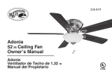
Unpack your fan and check the
contents. You should have the
following items:
a. Light fixture
b. 1, 7 watt E26 LED lamp
c. Glass shade
d. Glass frame
e. Part bag contents:
Nut
Spring Washer
Glass frame set screws (6)
Glass frame nuts (6)
Wire Nuts (2)
Pull chain and fob
Pull chain

4 | KICHLER.COM
Fig. 1
Fig. 2
Fig. 6
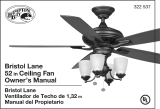
INSTALLING THE LIGHT KIT
REMEMBER to turn o the power before you begin.
Step 1. Remove and discard the center plug from the switch
housing. Attach the light kit to the switch housing by feeding the
light kit wires (black and white) through the hole in the center of the
switch housing, then screw the light kit onto the switch housing.
Attach the lock washer & nut on the inside of the switch housing
making sure the light kit is secure to prevent movement after
installation. (Fig. 1)
Step 2. Locate the white and blue wires inside the switch housing
labeled FOR LIGHT.
Step 3. Attach the wires from the light kit to the wires inside the
switch housing by pushing the polarized connections together.
- White wire to White wire
- Blue wire to Black wire
Step 4. Raise and hold the light kit assembly close to the mounting
plate of the ceiling fan. Push the square wire connectors together.
(Fig. 2)
NOTE: The square connectors are color coded. Match the color
coded sides of each plug and push. They will attach ONLY when
matched correctly.
Step 5. Carefully push all wires back into the switch housing, then
install the light kit assembly onto the mounting plate with 3 screws
provided. Be sure to tighten all screws. (Fig. 2)
Light kit
Center plug
Switch housing
Nut
Lock washer
Light kit
assembly
Square connectors
Screws
Mounting plate

BRIDGE POINT FAN LIGHT KIT | 5
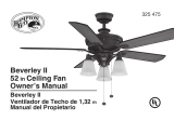
INSTALLING THE LAMP &
GLASS SHADE
1. Install the7 watt E26 LED lamp (provided) to the fixture socket.
2. Place the glass shade on the top over the glass frame and secure
tightly the glass frame with glass shade to the light kit assembly by
use the six set screws and nuts. Be sure to tighten all screws. (Fig. 3)
3. Feed the pull chain from the light kit assembly through the eyelet in
the chains holder.
4. Your installation is now complete. Restore electrical power and
enjoy your new ceiling fan light fixture.
Turn the power on and check the operation of your light fixture.
The pull chain controls the light On-O.
Fig. 3
Lamp
Glass shade
Chains holder
Glass frame
set screws
Glass frame
nuts
Glass frame
Light kit
assembly

www.kichler.com
KICHLER® LIGHTING
7711 EAST PLEASANT VALLEY ROAD P.O. BOX 318010
CLEVELAND, OHIO 44131-8010
CUSTOMER SERVICE 866.558.5706
8:30 AM TO 5:00 PM EST, MONDAY - FRIDAY
/