Page is loading ...

DEFINITY
®
AUDIX
®
System
Release 4.0
System Description Pocket Reference
585-300-214
Comcode 108356106
Issue 1
May 1999

Copyright 1999, Lucent Technologies
All Rights Reserved, Printed in U.S.A.
Notice
Every effort was made to ensure that the information in this book was complete and
accurate at the time of printing. However, information is subject to change.
Your Responsibility for Your System’s Security
Toll fraud is the unauthorized use of your telecommunications system by an unautho-
rized party, for example, persons other than your company’s employees, agents, sub-
contractors, or persons working on your company’s behalf. Note that there may be a risk
of toll fraud associated with your telecommunications system and, if toll fraud occurs, it
can result in substantial additional charges for your telecommunications services.
You and your system manager are responsible for the security of your system, such as
programming and configuring your equipment to prevent unauthorized use. The system
manager is also responsible for reading all installation, instruction, and system adminis-
tration documents provided with this product in order to fully understand the features
that can introduce risk of toll fraud and the steps that can be taken to reduce that risk.
Lucent Technologies does not warrant that this product is immune from or will prevent
unauthorized use of common-carrier telecommunication services or facilities accessed
through or connected to it. Lucent Technologies will not be responsible for any charges
that result from such unauthorized use.
Lucent Technologies Fraud Intervention
If you suspect you are being victimized by toll fraud and you need technical support or
assistance, call the appropriate BCS National Customer Care Center telephone num-
ber. Users of the MERLIN®, PARTNER®, and System 25 products should call 1 800
628 2888. Users of the System 75, System 85, DEFINITY® Generic 1, 2 and 3, and
DEFINITY® ECS products should call 1 800 643 2353. Customers outside the continen-
tal United States should contact their local Lucent representative, or call one of the
above numbers in the following manner:
• Dial the International Access Code; for example, 011.
• Dial the country code for the U.S., that is, 01.
• Lastly, dial either of the telephone numbers provided above.
Lucent Technologies Web Page
The world wide web home page for Lucent Technologies is:
http://www.lucent.com
Federal Communications Commission Statement
Part 15: Class A Statement. This equipment has been tested and found to comply with
the limits for a Class A digital device, pursuant to Part 15 of the FCC Rules. These limits
are designed to provide reasonable protection against harmful interference when the
equipment is operated in a commercial environment. This equipment generates, uses,
and can radiate radio-frequency energy and, if not installed and used in accordance
with the instructions, may cause harmful interference to radio communications. Opera-
tion of this equipment in a residential area is likely to cause harmful interference, in
which case the user will be required to correct the interference at his own expense.
Industry Canada (IC) Interference Information
This digital apparatus does not exceed the Class A limits for radio noise emissions set
out in the radio interference regulations of Industry Canada.
Le Présent Appareil Nomérique n’émet pas de bruits radioélectriques dépassant les lim-
ites applicables aux appareils numériques de la class A préscrites dans le reglement
sur le brouillage radioélectrique édicté par le Industrie Canada.
Trademarks
See the preface of this document.

Ordering Information
Call: Lucent Technologies BCS Publications Center
Voice 1 800 457-1235 International Voice 317 322-6791
Fax 1 800 457-1764 International Fax 317 322-6699
Write: Lucent Technologies BCS Publications Center
2855 N. Franklin Road
Indianapolis, IN 46219
Order: Document No. 585-300-214
Comcode 108356106
Issue 1, May 1999
For additional documents, refer to the section in “About This Document”
entitled “Related Resources.”
You can be placed on a standing order list for this and other documents
you may need. For more information on standing orders, or to be put on a
list to receive future issues of this document, contact the Lucent Technol-
ogies Publications Center.
Obtaining Products
To learn more about Lucent Technologies products and to order products,
contact Lucent Direct, the direct-market organization of Lucent Technolo-
gies Business Communications Systems. Access their web site at
www.lucentdirect.com. Or call the following numbers: customers 1 800
451 2100, account executives 1 888 778 1880 (voice) or 1 888 778 1881
(fax).
Warranty
Lucent Technologies provides a limited warranty on this product. Refer to
the “Limited Use Software License Agreement” card provided with your
package.
European Union Declaration of Conformity
The “CE” mark affixed to the equipment means that it conforms to the fol-
lowing directives. Lucent Technologies Business Communications Sys-
tems declares that DEFINITY AUDIX System equipment specified in this
document conforms to the referenced European Union (EU) Directives
and Harmonized Standards listed below:
EMC Directive 89/336/EEC
Low-Voltage Directive 73/23/EEC
Acknowledgment
This document was prepared by OMD Technical Publications, Lucent
Technologies, Denver, CO. and Columbus, OH.

DEFINITY AUDIX System Release 4.0
System Description Pocket Reference
585-300-214
Issue 1
May 1999
iv
Contents
Contents iv
About this Book vii
Intended Audiences vii
Supported Product Releases vii
Special Terminology vii
Trademarks viii
How to Order Additional Documentation viii
How to Comment on This Book viii
1 Features and Compatibility 1-1
Feature Overview 1-1
Features for the Customer Organization 1-1
Features for the Subscriber 1-2
Features for the System Administrator 1-3
Compatibility 1-4
Switches 1-4
Native and Non-native Mode 1-5
2 Design and Operation 2-1
TN568 Circuit Pack 2-2
Port Board Emulation 2-2
Flashware 2-2
Hard Disk Drive 2-2
Software 2-3
Networking 2-3
MO Disk Drive 2-7
Faceplate 2-8
On-board Cables 2-9
Operating Requirements 2-9
Space Requirements 2-9
Power Requirements 2-12
Environmental Requirements 2-12

DEFINITY AUDIX System Release 4.0
System Description Pocket Reference
585-300-214
Issue 1
May 1999
v
3 Capacity and Sizing 3-1
Voice Ports 3-1
Features that Affect Voice Ports 3-3
Voice Storage 3-4
Voice Storage for Announcement Sets 3-4
I
NTUITY Message Manager 3-5
Backup Limits on the MO Disk Drive 3-6
A Transition Notes A-1
System Design A-1
Native and Non-native Support A-1
Voice Ports A-2
Digital Networking Port A-3
Alarm Origination A-4
LEDs A-5
MO Disk Drive A-5
Switch Integration A-6
DCS Networking A-6
Analog Port Emulation A-6
Limited Availability for Control Link Integration A-7
B Customer Responsibilities B-1
Staff B-1
Environmental Requirements B-1
Cable Connections B-3
Abbreviations AB-1
Glossary GL-1
Index IN-1


Intended Audiences
vii
DEFINITY AUDIX System Release 4.0
System Description Pocket Reference
585-300-214
Issue 1
May 1999
About this Book
This book describes the DEFINITY
®
AUDIX
®
system Release 4.0. This
book is not intended to replace or modify instructions provided in
task-specific documentation for the DEFINITY AUDIX system.
Intended Audiences
This book was designed for the following Lucent Technologies audiences:
■ Customers
■ Marketing and sales teams
■ Field technicians
■ Technical support organizations
■ Educators and trainers
Supported Product Releases
This book covers DEFINITY AUDIX system Release 4.0. Appendix A also
includes some important changes from previous releases of the system.
Special Terminology
This book uses the word
system
to abbreviate the name of the DEFINITY
AUDIX system. Although Lucent Technologies’ documentation sometimes
uses the word
system
to refer to other products, such as DEFINITY
communication servers, this document uses the word
switch
to refer to
Lucent Technologies switches.
Lucent Technologies’ Technical Services Organization (TSO) and its
satellite organizations, such as the Technical Services Center (TSC), the
Sales Design & Support Center (SDSC), and the Multimedia Messaging
Implementation Support Center (MMISC), provide technical support for
Lucent Technologies customers in the U.S. Regional Centers of
Excellence (COEs) support Lucent Technologies customers outside the
U.S. This book broadly categorizes all of these organizations as the
Remote Services Center (RSC).

DEFINITY AUDIX System Release 4.0
System Description Pocket Reference
585-300-214
Issue 1
May 1999
Trademarks
viii
Trademarks
This book references the following products trademarked by Lucent
Tec hnolog ies:
■ DEFINITY
®
■ INTUITY
™
■ AUDIX
®
■ ProLogix
™
This book references the following products trademarked by their
respective vendors:
■ Windows
®
, Microsoft Corporation
■ dBASE III PLUS
®
, Ashton-Tate
■ U.S. Robotics
®
, 3Com Corporation
■ Sportster
®
, 3Com Corporation
How to Order Additional Documentation
In addition to this book, installation, maintenance, and administration
books are available for the DEFINITY AUDIX system.
These books or any other Lucent Technologies product documentation
can be ordered from the Lucent Technologies Product Publications
Catalog website:
www.lucent.com/enterprise/documentation
How to Comment on This Book
The reader comment card is located in the front of this book. While we
have tried to make this document fit your needs, we are interested in
your suggestions for improving it and encourage you to complete and
return a reader comment card.
Please send your comments to:
Lucent Technologies
Product Publications Department
Room 22-2J20
11900 North Pecos Street
Denver, CO 80234
Fax: (303) 538-1741

Features and Compatibility
1-1
Feature Overview
DEFINITY AUDIX System Release 4.0
System Description Pocket Reference
585-300-214
Issue 1
May 1999
Chapter 1 — Features and Compatibility
With the high-quality voice messaging system DEFINITY AUDIX system
Release 4.0, customers don’t have to answers telephones, and they can
exchange messages at times when it is unnecessary or inconvenient to
talk in person. The DEFINITY AUDIX system saves valuable office space
and simplifies system administration by residing inside the customer’s
switch and sharing a single administration terminal. These features, as
well as new enhancements for reliability, make the DEFINITY AUDIX
system Release 4.0 a desirable voice messaging solution for customers
worldwide.
Feature Overview
The DEFINITY AUDIX system offers many features for customer
organizations, individual subscribers, and DEFINITY AUDIX system
administrators to help streamline information exchange among
employees.
Features for the Customer Organization
Here are a few of the things the DEFINITY AUDIX system can do to help
improve voice messaging efficiency in customer organizations:
■ Support up to 2000 local subscribers and 100,000 remote
subscribers
■ Store up to 100 hours of voice messages
■ Exchange messages with other voice messaging systems via
Digital Networking and Audio Messaging Interchange
Specification (AMIS) Analog Networking
■ Post greetings and instructions in up to 9 languages from 30
available announcement sets, including a set for teletypewriters
(TTYs)
■ Answer calls with different messages according to the time of day
and holidays
■ Broadcast messages to large groups of subscribers
simultaneously
■ Record messages with the highest voice quality available for
digital voice messaging
1
■ Deter toll fraud with the Call Transfer Restriction features and
Administration Password Aging
■ Allow customers to track and bill subscribers’ calls with the
Administration and Data Acquisition Package (ADAP)
1. AUDIX software uses a voice-encoding algorithm known as
code-excited linear predication (CELP). CELP captures the
nuances and subtle inflections of the human voice, which are an
integral part of interpersonal communication.

DEFINITY AUDIX System Release 4.0
System Description Pocket Reference
585-300-214
Issue 1
May 1999
Features and Compatibility
1-2
Feature Overview
■ Maintain a direct connection with Lucent Technologies’ Remote
Services Center (RSC) to spur immediate support for
maintenance problems
■ Ensure the stability of services by automatically backing up data
on removable optical disks (also called
MO
disks)
■ Save money with a small voice messaging system that resides in
the customer’s switch
Savings from A Smaller System
The space the DEFINTY AUDIX system Release 4.0 requires from the
customer’s switch has decreased from previous releases of the system
by 60%. The system now only requires two universal port slots in the
customer’s DEFINITY switch or one slot in a Compact Modular Cabinet
(CMC),
2
while previous releases required five slots.
For smaller switches, such as the CMC, a voice messaging system that
only takes one or two slots can make expanding the customer’s
telecommunications capacity much more efficient in the long run. With a
two-slot voice messaging system, customers can further expand their
telecommunications capacities—adding voice ports or local area
network (LAN) features, for example—before they must invest in switch
upgrades.
Features for the Subscriber
Subscribers can perform many tasks with the DEFINITY AUDIX system
that make communication faster, easier, and more convenient:
■ Store incoming and outgoing messages in a voice mailbox
■ Use a streamlined voice menu to speed through complex
transactions
■ Post multiple personal greetings on the system, which
subscribers can change according to their availability
■ Compose spoken messages with Voice Mail, which they can
send to one or more other subscribers on the DEFINITY AUDIX
system
■ Send messages to many recipients at once using mailing lists
■ Address voice mail messages by typing recipients’ names, rather
than their extensions, on their telephone keypads
■ Advance or rewind messages as they listen
■ Receive visual notification of new messages with message
waiting indicators (MWIs)—lights or display screens on
subscribers’ telephones that indicate new messages
2. For the system to take one slot, it must be installed in slot 6.

DEFINITY AUDIX System Release 4.0
System Description Pocket Reference
585-300-214
Issue 1
May 1999
Features and Compatibility
1-3
Feature Overview
■ Receive audible notification for all incoming messages or just
priority messages on remote telephones or pagers
■ Retrieve, create, and send messages on their personal
computers (PCs) using I
NTUITY Message Manager
The Advantages of INTUITY Message Manager
INTUITY Message Manager software provides DEFINITY AUDIX system
subscribers access to the system through a TCP/IP connection with their
PCs.
This PC interface allows subscribers to access and organize their
messages much more quickly than an audible interface. Here are a few
of the things DEFINITY AUDIX system subscribers can do with I
NTUITY
Message Manager:
■ Receive visual notification of their voice mail messages on their
PCs
■ View their entire message lists at once
■ Read message headers, including callers’ names and telephone
numbers, to prioritize the messages they receive and listen to the
messages in the order they choose
■ Access voice mail features through a visual, Windows-based
interface
■ Record, edit, and play back messages and personal greetings
using a mouse, rather than a telephone keypad
■ Forward and reply to messages
■ Annotate messages with a subject line
■ Save messages on their PCs, creating a permanent record of
important messages and freeing storage space on the DEFINITY
AUDIX system
■ Set up mailing lists and administer personal greetings and
outcalling
3
with ease using a keyboard
■ Access the system’s subscriber directory and mailing lists
Features for the System Administrator
The DEFINITY AUDIX system offers many features that allow system
administrators to easily track system use and change system functions
to meet subscribers’ needs. A few of those features are described here:
3. With the Outcalling feature, the DEFINITY AUDIX system calls
subscribers at a number of their choice, including pagers, to notify
them of incoming messages.

DEFINITY AUDIX System Release 4.0
System Description Pocket Reference
585-300-214
Issue 1
May 1999
Features and Compatibility
1-4
Compatibility
■ The Class of Service feature allows administrators to manage
system resources by defining up to 12 categories of subscribers
with varying access to system features.
■ The Traffic Reports feature and ADAP allow administrators to
effectively track subscribers’ system use, identify where to
allocate system resources, and decide when to upgrade
hardware.
■ The Administration Password Aging feature helps prevent
unauthorized system access.
■ The Alarm Origination feature provides the administrator
immediate technical support by automatically calling Lucent
Technologies’ RSC to report alarms.
Compatibility
Before customers install the DEFINITY AUDIX system, they should
ensure they have a switch release that can accommodate the system.
Switches
The DEFINITY AUDIX system can operate in any of the following
switches:
■ System 75 R1V3
■ System 75 R1V3n
■ System 75 XE
■ DEFINITY Communications System Generic 1
■ DEFINITY Communications System Generic 3i
■ DEFINITY Communications System Generic 3s
■ DEFINITY Communications System Generic 3si
■ DEFINITY Communication System Generic 3csi (ProLogix)
■ DEFINITY Communications System Generic 3vs
■ DEFINITY Communications System Generic 3r
Tab le 1-1
lists special considerations for using the DEFINTIY AUDIX
system with these switches.

DEFINITY AUDIX System Release 4.0
System Description Pocket Reference
585-300-214
Issue 1
May 1999
Features and Compatibility
1-5
Compatibility
Table 1-1. Considerations for the DEFINTIY AUDIX system
Native and Non-native Mode
The DEFINITY AUDIX system can operate with almost any Lucent
Technologies switch release. However, only DEFINITY switch releases
7.1 and later will recognize the DEFINITY AUDIX system’s TN568 circuit
pack.
The circuitry for the DEFINITY AUDIX system is assigned a vintage
number that communicates the system’s function to the switch. The
vintage number for DEFINITY AUDIX system Release 4.0 is 48. Switch
releases 7.1 and later recognize this number as belonging to the
DEFINITY AUDIX system’s TN568 circuit pack. Switch releases earlier
than 7.1recognize vintage number 48 as belonging to one of two digital
port circuit packs:
■ TN754, an 8-port digital circuit pack
■ TN2181, a 16-port digital circuit pack
4
When the DEFINTY AUDIX system operates in a switch that recognizes
its vintage number as a TN568, the system is operating in
native mode
.
When the DEFINITY AUDIX system operates in a switch that recognizes
the system as a TN754 or TN2181 circuit pack, it is operating in
non-native mode
.
5
Switch releases Considerations for the DEFINTIY AUDIX system
All Calls using loopback trunks cannot terminate at the
DEFINITY AUDIX system
Earlier than 5.3 These switches do not support the use of multifunction
analog telephones (MFATs)
Earlier than
2g.04.5.0.099
These switches do not support the Transfer Out of AUDIX
feature
4. Even though the TN2181 is a 16-port digital station circuit pack,
the DEFINITY AUDIX system will only support 12 voice ports.
Administering the DEFINITY AUDIX system’s voice ports for
TN2181 emulation requires the use of special procedures. For
more information about voice port administration, see Chapter 2
,
Chapter 3, Appendix A, and
Installation and Switch Administration
for the DEFINITY AUDIX System Release 4.0
, 585-300-122
.
5. Even though the DEFINITY AUDIX system is emulating a circuit
pack other than the TN568, the digital port circuit pack the system
is emulating will still register a vintage number 48. This vintage
number is unique to DEFINITY AUDIX system Release 4.0. See the
system description for the customer’s switch for more information
about accessing circuit packs’ vintage numbers.

DEFINITY AUDIX System Release 4.0
System Description Pocket Reference
585-300-214
Issue 1
May 1999
Features and Compatibility
1-6
Compatibility
Operating in non-native mode does not affect subscribers’ or outside
callers’ use of the system. System administrators, however, should be
aware that messages from the switch, such as alarms, that refer to a
TN754 or a TN2181 circuit pack the system is emulating may actually
refer to the DEFINITY AUDIX system.
NOTE:
Lucent Technologies strongly recommends that the DEFINITY
AUDIX system emulates a TN2181 digital port circuit pack in
switch versions 2 and later. A TN2181 emulation supports a
maximum of 12 voice ports, while a TN754 emulation only
supports a maximum of 8 voice ports. If the DEFINITY AUDIX
system emulates a TN2181 circuit pack, system expansion may be
easier. Switch versions earlier than 2 do not support TN2181
circuit pack emulation.
Tab le 1-2
shows which switches and switch software releases support
the DEFINITY AUDIX system and whether or not they support the system
in native mode. For more information about the TN568 circuit pack or the
system’s operations native and non-native mode, see Chapter 2
. For
more information about Alarm Origination and the DEFINITY AUDIX
system’s interactions with the switch, see Chapter 3
.

DEFINITY AUDIX System Release 4.0
System Description Pocket Reference
585-300-214
Issue 1
May 1999
Features and Compatibility
1-7
Compatibility
Table 1-2. Switch Releases Compatible with the DEFINITY AUDIX
System
Compatible switch releases
Do these software
releases support the
system in native mode?
System 75
■ Release 1 Version 3
■ Release 1 Version 3n
No
No
G1
■ G1.1
■ G1.1n
No
No
G3vs
■ Version 1 to Version 4
■ Release 5 to Release 6
No
No
G3s
■ Version 1 to Version 3 No
G3i
■ Version 1 to Version 3 No
G3si
■ Version 4
■ Release 5 to Release 6
No
No
G3si
■ Release 7 or later Yes
G3csi
■ Release 6 No
G3csi
■ Release 7 or later Yes
G3r
■ Version 1 to Version 4
■ Release 5 to Release 6
No
No
G3r
■ Release 7 or later Yes

DEFINITY AUDIX System Release 4.0
System Description Pocket Reference
585-300-214
Issue 1
May 1999
Features and Compatibility
1-8
Compatibility

Design and Operation
2-1
DEFINITY AUDIX System Release 4.0
System Description Pocket Reference
585-300-214
Issue 1
May 1999
Chapter 2 — Design and Operation
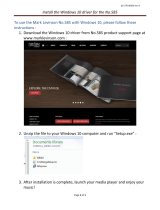
Figure 2-1 shows the five main hardware components that compose the
DEFINITY AUDIX system:
■ TN568 circuit pack
■ Hard disk drive
■ Magneto-optical (MO) disk drive
■ Faceplate
■ On-board H600 cables
Figure 2-1. The DEFINITY AUDIX System
This chapter describes each of these components in detail and its role in
voice messaging on the DEFINITY AUDIX system. This chapter also
describes the system’s requirements for resources from the customer’s
switch, such as space and power.
E
m
e
r
R
e
s
e
t
S
h
u
t
d
o
w
n
ckdx568t KLC 012099
Hard disk drive
H600-501
Magneto-optical
disk drive
TN568
Circuit pack
Faceplate
H600-502
H600-500

DEFINITY AUDIX System Release 4.0
System Description Pocket Reference
585-300-214
Issue 1
May 1999
Design and Operation
2-2
TN568 Circuit Pack
TN568 Circuit Pack
The TN568 circuit pack holds the systems main circuitry and performs
system’s main processing functions, including message routing,
self-diagnosis, and Alarm Origination.
Port Board Emulation
The TN568 holds the system’s voice ports. These voice ports
correspond to the voice ports on a TN754 or TN2181 circuit pack.
DEFINITY switch releases 7.1 and later recognize the TN568 circuit
pack. However, the system’s voice ports interact with the switch like the
voice ports on a TN754 or TN2181 circuit pack regardless of whether the
system is operating in native or non-native mode. For more information
about digital port emulation, see Chapter 1.
Flashware
The TN568 circuit pack uses
flashware
to store the sequences it uses to
boot the system and programs specific to the TN568. Flashware are
programs that reside on flash programmable read-only memory
(FPROMs). FPROMs are hardware that reside on the TN568 and are
protected from accidental erases or rewrites. Copies of all the active
flashware programs are also stored on the hard disk.
If the customer installs software upgrades or fixes, the new program is
transferred from a MO disk to the hard disk. When the system reboots,
the new program automatically transfers from the hard disk to the
FPROMs and replaces the existing flashware.
Hard Disk Drive
The hard disk drive stores the system’s AUDIX software, subscriber
information and voice messages.
Voice messages that customers may store on the system include voice
mail, personal greetings, automated attendants, and announcement
sets—the sets of automated, verbal instructions that compose the
system’s user interface.
The hard disk drive provides up to 100 hours of voice storage. The
system comes with a minimum of 10 hours of voice storage. Customers
can purchase additional voice storage in five-hour blocks.

DEFINITY AUDIX System Release 4.0
System Description Pocket Reference
585-300-214
Issue 1
May 1999
Design and Operation
2-3
Hard Disk Drive
Software
AUDIX software allows the DEFINITY AUDIX system to communicate
with the switch through a telephone-like interface. This type of operation
is called set-type emulation. The commands that subscribers and the
switch use to access the system’s software correspond to the interface
on a digital telephone, or set.
The digital set the system emulates depends on whether the system is
operating in native or non-native mode. In switch releases earlier than
7.1, the DEFINITY AUDIX system emulates a 7405D digital telephone. In
switch releases 7.1 and later, the system communicates with the switch
using an ADX16D set-type interface, through which the switch can
recognize the system’s AUDIX software.
1
Networking
Because of its telephone-like interface, the system can send and receive
messages from other voice messaging systems as a telephone can.
AUDIX software helps the system to communicate efficiently with other
AUDIX systems.
The DEFINITY AUDIX system has two networking options that use these
capabilities for message exchange:
■ AMIS Analog Networking
■ Digital Networking
AMIS Analog Networking
AMIS is a standard protocol among voice messaging systems. AMIS
Analog Networking uses the Message Delivery feature to send
messages to subscribers on other voice messaging systems that use
the AMIS protocol.
AMIS Analog Networking sends a message through the system’s voice
ports much like a telephone call. The recipient’s voice mail system
receives the message as it would receive any other voice message and
stores it in the recipient’s voice mailbox. Other voice messaging systems
can send messages to the DEFINITY AUDIX system in the same way.
Digital Networking
Digital Networking is an efficient way for DEFINITY AUDIX, AUDIX R1,
I
NTUITY, and Interchange systems to communicate with each other
without using the systems’ voice ports. The DEFINITY AUDIX system has
one Digital Networking port that can be dedicated solely to Digital
1. For more information about digital station emulations, see
Installation and Switch Administration for the DEFINITY AUDIX
System Release 4.0
, 585-300-122.

DEFINITY AUDIX System Release 4.0
System Description Pocket Reference
585-300-214
Issue 1
May 1999
Design and Operation
2-4
Hard Disk Drive
Networking features. In its maximum configuration, the DEFINITY AUDIX
system can connect through this Digital Networking channel to up to 100
remote systems, or
nodes
.
2
Digital Networking offers several advantages over AMIS Analog
Networking:
■ Digital Networking is more secure than AMIS Analog Networking.
■ Digital Networking uses Lucent Technologies’ Digital
Communications Protocol (DCP) to send subscriber profiles and
message status information along with messages, while AMIS
does not send this information.
■ Digital Networking messages have higher voice quality than
AMIS messages because Digital Networking uses CELP
encoding.
There is one important consideration, however, for customers who want
to use Digital Networking. If customers use Digital Networking, the
DEFINITY AUDIX system will have a maximum of 8 voice ports, rather
than 12. Tab le 2-1
shows the maximum number of voice ports the
DEFINTIY AUDIX system can have with and without Digital Networking.
High-speed Digital Networking Connections
The DEFINTIY AUDIX system offers three types of Digital Networking
configurations: DCP Mode 1, DCP Mode 2, and DCP Mode 3.
DCP Mode 1 and DCP Mode 3 connections are high-speed Digital
Networking connections. DCP Mode 1 and DCP Mode 3 connections
require high-speed facilities to operate, but these connections offer
advantages where there is heavy voice messaging traffic among
customer sites. These high-speed Digital Networking connections can
accommodate the maximum numbers of local subscribers (2000) and
remote subscribers (100,000) the system allows.
2. This configuration is only available with high-speed Digital
Networking connections.
Table 2-1. Maximum Voice Ports and Digital Networking Ports
Digital Networking ports Voice ports
Without Digital Networking 0 12
1
1. In switch releases earlier than Version 2, the system has a
maximum of 8 voice ports.
With Digital Networking 1 8
/