Pro-face Replacement Guidebook GP4000TW to ST-6300T/6500T EN User guide
- Type
- User guide

Page 1© 2021 Pro-face. All Rights Reserved. |
Replacement Guidebook (Software)
The 2nd Edition Dec.2021

Page 2© 2021 Pro-face. All Rights Reserved. |
Update History
Date Edition Updated Slide Description
2020/11/12 - Newly created
2021/12/15 2 10 Add more information on the Notes of using the Convert Resolution.

Page 3© 2021 Pro-face. All Rights Reserved. |
For the supported software for each hardware, see “About Software compatibility” in “Replacement
Guidebook (Hardware)".
Preface


Page 5© 2021 Pro-face. All Rights Reserved. |
1. Replacement of GP-Pro EX to GP-Pro EX

Page 6© 2021 Pro-face. All Rights Reserved. |
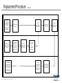
Replacement Procedure –Work Flow-
Installation
Screen
Communication
Check the
compatibility of
the hardware
with
Replacement
Guidebook.
Remove Model
in use unit.
Install
recommended
substitute unit.
Connect the
Power Supply
Check the
performance and
start operation.
Receive screen
data from Model
in use unit.
Change the
model type of
the received
screen data
using GP-Pro EX.
Check and
modify the data
on GP-Pro EX.
Transfer the
screen data to
the
recommended
substitute unit.
Check the
connection between
the recommended
substitute unit and a
PLC in the GP-Pro
EX Device/PLC
Connection Manual.
Start connection
and check the
communication
Connect
Recommended
substitute unit
and PLC with the
PLC’s cable.

Page 7© 2021 Pro-face. All Rights Reserved. |
Replacement Procedure –Preparation-
Requirements for receiving screen data from Model in use unit *1 PC in which GP-Pro EX Transfer Tool is installed. *2
A USB transfer cable : CA3-USBCB-01(Type A- Type A)
A USB data transfer cable : ZC9USCBMB1(Type A- Type mini B) *3
A commercial USB cable (Type A- Type mini B) *3
※Possible to send/receive a screen via a SD card , a USB storage device or Ethernet.
Requirements for converting screen data of Model in use unit and transferring
the converted data to Recommended substitute unit. PC with GP-Pro EX installed *4
Transfer Cable (The following Cables can be used.)
A USB transfer cable : CA3-USBCB-01(Type A- Type A)
A USB data transfer cable : ZC9USCBMB1(Type A- Type mini B) *3
A communication USB cable (Type A- Type mini B) *3
※Possible to send/receive a screen via a SD card , a USB storage device or Ethernet.
*1: This step is required if screen data is saved only in the GP unit, not in any other device.
*2: Please use the same version or later as or than that of the software used during creating screens on GP-3500T/GP-3510T. If you don’t know the version, we recommend you to use the
newest version. For the newest version, you can download the transfer tool from our web site called [OtasukePro!] (http://www.pro-face.com/otasuke/download/freesoft/gpproex_transfer.htm).
*3: It can be used with GP4000 Series or later models.
*4: Please check the compatible version of each model from our website. (https://www.proface.com/ja/product/soft/gpproex/supported_models)

Page 8© 2021 Pro-face. All Rights Reserved. |
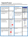
Replacement Procedure –Receive Screen data from Model in use unit (GP-Pro EX)-
In this section, we will introduce how to receive screen data with a USB transfer cable as an example. If you have backed up screen data, this step is unnecessary, skip to the
next section.
1. Connect your PC and Model in use unit with a USB
transfer cable. If the driver of the cable has not been
installed on your PC yet, a dialog box will appear.
Please follow the instructions.
2. Start the Transfer Tool of GP-Pro EX.
3. Make sure that the [Device] in the “Transfer Settings
Information” is set to [USB]. If not, click the [Transfer
Setting] button to open the “Transfer Setting” dialog
box. Select [USB] in the Communication Port Settings
field and click [OK].
4. Start GP-Pro EX Transfer Tool and click the [Receive
Project] button.
5. Click [Receive Project], and the following dialog box will
appear. Specify a place to save the received data in and
a project file name, and then click [Save] to start transfer.
6. The following dialog box appears during transfer and you
can check the communication status. (The display unit
enters the Transferring mode and communication with the
device such as a PLC is terminated.)
7. When transfer is completed, the status displayed in the
dialog box will change from [Transferring] to [Complete
Transfer]. Click [Close] to close the dialog box.
8. Close the Transfer Tool.

Page 9© 2021 Pro-face. All Rights Reserved. |
Replacement Procedure –Receive Screen data from Model in use unit (GP-Pro EX)-
1. The “Hardware Installation” dialog box as shown on the right may appear during installing the USB driver depending on the security level of
Windows®. Click [Continue Anyway] to start installing the driver. When installation is completed, click [Finish].
2. When a file exists, the window that confirms whether or not to overwrite the file will be displayed.
3. If you receive the project files that use SD card/ USB flash data such as Recipe Function (CSV data), the following dialog box will appear during
transfer. Specify a place to save the SD card/USB flash data in. Click [OK], and the [Receive Project] dialog box will return and transfer will be
completed.
NOTES

Page 10© 2021 Pro-face. All Rights Reserved. |
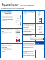
Replacement Procedure –Change model to recommended substitute unit (GP-Pro EX)-
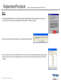
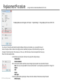
The Display Module can be Changed on the “Project” -> “System Settings” -> “Change Display Unit” screen of GP-Pro EX.
If you check on [Convert Resolution] when changing the Display Unit type (as shown below), you can adjust both size and
location of the part and the text relative to the display resolution automatically. But please note that their width gets larger due
to change of horizontal resolution of the screen area. In this case, confirm their size and location and adjust them if necessary.
Please check some examples below.
•A function that requires absolute coordinates. Please adjust the settings manually.
-Global window
-Position Animation
•Due to font size and resolution restrictions, manual changes may be required. Please resize them if needed
-Font: In the case of using Standard font, the size will be smaller. You can improve by using Stroke font or Image font.
-Objects
-Parts
-Images
-Alarm parts
•Position may differ from the original project. Please check the coordinate of the window and adjust if needed.
-Window display

Page 11© 2021 Pro-face. All Rights Reserved. |
Replacement Procedure –Transfer screen data to recommended substitute unit (GP-Pro EX)-
In this section, we will introduce how to transfer screen data with a USB transfer cable as an example.
1. Connect your PC and the recommended substitute unit
with a USB transfer cable. If the driver of the cable has
not been installed on you PC, a dialog box will appear.
Please follow the instructions.
2. Turn on the power of Recommended substitute unit.
The “Initial Start Mode” screen will appear on the
display unit. After transferring a project file once, this
screen will not appear again.
3. On the GP-Pro EX’s State Toolbar, click the [Transfer
Project] icon to open the Transfer Tool.
To transfer a different project file, click the
[Select Project] button and select a project file.
4. Make sure that the [Device] in the “Transfer Settings
Information” is set to [USB]. If not, click the [Transfer
Setting] button to open the “Transfer Setting” dialog box.
Select [USB] in the Communication Port Settings field
and click [OK].
5. Click [Send Project] to start transfer.
When the following dialog box appears, click [Yes].
This dialog box doesn’t appear when the same project
file is sent again.
6. The following dialog box appears during transfer and
you can check the communication status. (The display
unit enters the Transferring mode and communication
with the device such as a PLC is terminated.)
7. When transfer is completed, the status displayed in the
dialog box will change from [Transferring] to [Complete
Transfer]. Click [Close] to close the dialog box.
8. Close the Transfer Tool
9. Click the [X] mark on top right of the screen or [Project]-
>[Exit] to close GP-Pro EX.

Page 12© 2021 Pro-face. All Rights Reserved. |
2. Replacement of GP-Pro EX to BLUE

Page 13© 2021 Pro-face. All Rights Reserved. |
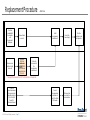
Startup the
BLUE and
create a new
project based
on the received
project data from
GP-Pro EX.
* The project file conversion from GP-Pro EX to BLUE is not supported.
Installation
Screen
Communication
Check the
compatibility of
the hardware
with
Replacement
Guidebook.
Remove Model
in use unit.
Install
recommended
substitute unit.
Connect the
Power Supply
Check the
performance and
start operation.
Check the
connection between
the recommended
substitute unit and a
PLC in the BLUE
Device/PLC
Connection Manual.
Start connection
and check the
communication
Connect
Recommended
substitute unit
and PLC with the
PLC’s cable.
Receive screen
data from Model
in use unit.
Transfer the
screen data to
the
recommended
substitute unit.
Replacement Procedure –Work Flow-

Page 14© 2021 Pro-face. All Rights Reserved. |
Requirements for receiving screen data from Model in use unit *1 PC in which GP-Pro EX Transfer Tool is installed. *2
A USB transfer cable : CA3-USBCB-01(Type A- Type A)
A USB data transfer cable : ZC9USCBMB1(Type A- Type mini B) *3
A commercial USB cable (Type A- Type mini B) *3
※Possible to send/receive a screen via a SD card , a USB storage device or Ethernet.
Requirement for creating new project and transferring the data to
Recommended substitute unit. PC with BLUE installed. *4
Transfer Cable (The following Cables can be used.)
A USB data transfer cable (for SP5000/GP4100) : ZC9USCBMB1(Type A- Type mini B)
A commercial USB mini B transfer cable (for SP5000/GP4100)
A USB transfer cable (for ST6000/STM6000) :PFXZUSCBMB2(Type A- Type micro B)
A commercial USB micro B transfer cable (for ST6000/STM6000)
※Possible to send/receive a screen via a SD card , a USB storage device or Ethernet.
*1: This step is required if screen data is saved only in the GP unit, not in any other device.
*2: Please use the same version or later as or than that of the software used during creating screens on GP-3500T/GP-3510T. If you don’t know the version, we recommend you to use the
newest version. For the newest version, you can download the transfer tool from our web site called [OtasukePro!] (http://www.pro-face.com/otasuke/download/freesoft/gpproex_transfer.htm).
*3: It can be used with GP4000 Series or later models.
*4: Please check the compatible version of each model from below.
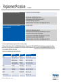
Replacement Procedure –Preparation-
Series Product Name Model Number Supported version
SP5000 SP-5B10 Power BOX PFXSP5B10 BLUE V.3.0 or later
SP-5B90 Xtreme Box PFXSP5B90 BLUE V.3.1 SP1 or later
SP-5B00 Standard Box PFXSP5B00 BLUE V.3.1 SP1 or later
ST6000 ST-6*00WA PFXST6*00WAD BLUE V.3.1 or later
STM6000 STM-6*00WA PFXSTM6*00WAD BLUE V.3.1 SP1B or later
GP4100 GP-411*T PFXGP411*T2D BLUE V.3.0 or later
Pro-face IPC, PC/AT - - BLUE V.3.0 or later

Page 15© 2021 Pro-face. All Rights Reserved. |
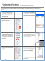
Replacement Procedure –Receive Screen data from Model in use unit (GP-Pro EX)-
In this section, we will introduce how to receive screen data with a USB transfer cable as an example. If you have backed up screen data, this step is unnecessary, skip to the
next section.
1. Connect your PC and Model in use unit with a USB
transfer cable. If the driver of the cable has not been
installed on your PC yet, a dialog box will appear.
Please follow the instructions.
2. Start the Transfer Tool of GP-Pro EX.
3. Make sure that the [Device] in the “Transfer Settings
Information” is set to [USB]. If not, click the [Transfer
Setting] button to open the “Transfer Setting” dialog
box. Select [USB] in the Communication Port Settings
field and click [OK].
4. Start GP-Pro EX Transfer Tool and click the [Receive
Project] button.
5. Click [Receive Project], and the following dialog box will
appear. Specify a place to save the received data in and
a project file name, and then click [Save] to start transfer.
6. The following dialog box appears during transfer and you
can check the communication status. (The display unit
enters the Transferring mode and communication with the
device such as a PLC is terminated.)
7. When transfer is completed, the status displayed in the
dialog box will change from [Transferring] to [Complete
Transfer]. Click [Close] to close the dialog box.
8. Close the Transfer Tool.

Page 16© 2021 Pro-face. All Rights Reserved. |
Replacement Procedure –Transfer screen data to recommended substitute unit (BLUE)-
1. Refer to the GP-Pro EX screen data received in
advance and create a new project with BLUE.
2. Connect your PC and the recommended substitute unit
with a USB transfer cable. If the driver of the cable has
not been installed on you PC, a dialog box will appear.
Please follow the instructions.
3. When the power of the recommended replacement
model is turned on, the "Initial transfer mode" screen is
displayed.
Once you transfer the project, this screen will not be
displayed again.
4. Select "Target" from "System Settings" in the BLUE
Project Explorer window.
If you want to transfer a different project file,
you can click the "Open Project" button and select
the project file.
5. In Properties window, go to [Function] tab ➞[Basic] tab
and acknowledge that [Type] in [Transfer Method] is
[USB Cable].
6. From the [Security Setting] select [Enable] and in the
[Security Level] field set the security level required to
perform transfer operations.
*In the [Security Setting] if [Disable] is selected, the project
file is transferred without user authentication.
7. On the Application toolbar, click the icon.
8. The Download Manager dialog box displays the status.
You will be prompted for a [User name] and [Password].
Enter the user name and password for a user that
satisfies the required security level and click [OK].
9. Close the Download Manager dialog box after the
transfer is complete.
After the project has been transferred successfully,
the display unit restarts and runs the transferred project.
In this section, we will introduce how to transfer screen data with a USB transfer cable as an example.

Page 17© 2021 Pro-face. All Rights Reserved. |
-
 1
1
-
 2
2
-
 3
3
-
 4
4
-
 5
5
-
 6
6
-
 7
7
-
 8
8
-
 9
9
-
 10
10
-
 11
11
-
 12
12
-
 13
13
-
 14
14
-
 15
15
-
 16
16
-
 17
17


Pro-face Replacement Guidebook GP4000TW to ST-6300T/6500T EN User guide
- Type
- User guide
Ask a question and I''ll find the answer in the document
Finding information in a document is now easier with AI
Related papers
-
Pro-face Replacement Guidebook GP4000W to ST6000 User guide
-
-
-
-
Pro-face GP-Viewer EX Operating instructions
-
-
-
-
-
Other documents
-
Mitsubishi Electric GT Designer2 Version2 Basic Owner's manual
-
-
-
-
-
Hitachi S10V Series User manual
-
Omron Sysmac CX Operating instructions
-
OPTO 22 groov Box User guide
-
Mitsubishi GT10 User manual
-
 ProSoft Technology MVI56-EGD User manual
