A - 18
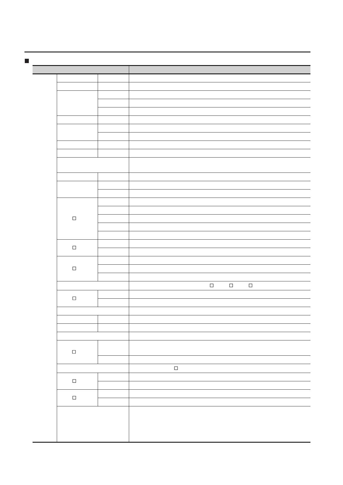
ABBREVIATIONS AND GENERIC TERMS
GOT
(Continued to next page)
Abbreviations and generic terms Description
GOT1000
Series
GT1695 GT1695M-X Abbreviation of GT1695M-XTBA, GT1695M-XTBD
GT1685 GT1685M-S Abbreviation of GT1685M-STBA, GT1685M-STBD
GT1675
GT1675M-S Abbreviation of GT1675M-STBA, GT1675M-STBD
GT1675M-V Abbreviation of GT1675M-VTBA, GT1675M-VTBD
GT1675-VN Abbreviation of GT1675-VNBA, GT1675-VNBD
GT1672 GT1672-VN Abbreviation of GT1672-VNBA, GT1672-VNBD
GT1665
GT1665M-S Abbreviation of GT1665M-STBA, GT1665M-STBD
GT1665M-V Abbreviation of GT1665M-VTBA, GT1665M-VTBD
GT1662 GT1662-VN Abbreviation of GT1662-VNBA, GT1662-VNBD
GT1655 GT1655-V Abbreviation of GT1655-VTBD
GT16
Abbreviation of GT1695, GT1685, GT1675, GT1672, GT1665, GT1662, GT1655,
GT16 Handy GOT
GT1595 GT1595-X Abbreviation of GT1595-XTBA, GT1595-XTBD
GT1585
GT1585V-S Abbreviation of GT1585V-STBA, GT1585V-STBD
GT1585-S Abbreviation of GT1585-STBA, GT1585-STBD
GT157
GT1575V-S Abbreviation of GT1575V-STBA, GT1575V-STBD
GT1575-S Abbreviation of GT1575-STBA, GT1575-STBD
GT1575-V Abbreviation of GT1575-VTBA, GT1575-VTBD
GT1575-VN Abbreviation of GT1575-VNBA, GT1575-VNBD
GT1572-VN Abbreviation of GT1572-VNBA, GT1572-VNBD
GT156
GT1565-V Abbreviation of GT1565-VTBA, GT1565-VTBD
GT1562-VN Abbreviation of GT1562-VNBA, GT1562-VNBD
GT155
GT1555-V Abbreviation of GT1555-VTBD
GT1555-Q Abbreviation of GT1555-QTBD, GT1555-QSBD
GT1550-Q Abbreviation of GT1550-QLBD
GT15
Abbreviation of GT1595, GT1585, GT157 , GT156 , GT155
GT145
GT1455-Q Abbreviation of GT1455-QTBDE, GT1455-QTBD
GT1450-Q Abbreviation of GT1450-QLBDE, GT1450-QLBD
GT14 Abbreviation of GT1455-Q, GT1450-Q
GT1275 GT1275-V Abbreviation of GT1275-VNBA, GT1275-VNBD
GT1265 GT1265-V Abbreviation of GT1265-VNBA, GT1265-VNBD
GT12 Abbreviation of GT1275, GT1265
GT115
GT1155-Q
Abbreviation of GT1155-QTBDQ, GT1155-QSBDQ, GT1155-QTBDA, GT1155-QSBDA,
GT1155-QTBD, GT1155-QSBD
GT1150-Q Abbreviation of GT1150-QLBDQ, GT1150-QLBDA, GT1150-QLBD
GT11
Abbreviation of GT115 , GT11 Handy GOT,
GT105
GT1055-Q Abbreviation of GT1055-QSBD
GT1050-Q Abbreviation of GT1050-QBBD
GT104
GT1045-Q Abbreviation of GT1045-QSBD
GT1040-Q Abbreviation of GT1040-QBBD
GT1030
Abbreviation of GT1030-LBD, GT1030-LBD2, GT1030-LBL, GT1030-LBDW,
GT1030-LBDW2, GT1030-LBLW, GT1030-LWD, GT1030-LWD2, GT1030-LWL,
GT1030-LWDW, GT1030-LWDW2, GT1030-LWLW, GT1030-HBD, GT1030-HBD2,
GT1030-HBL, GT1030-HBDW, GT1030-HBDW2, GT1030-HBLW, GT1030-HWD,
GT1030-HWD2, GT1030-HWL, GT1030-HWDW, GT1030-HWDW2, GT1030-HWLW


