Page is loading ...

TCD-R5ML rev.0114
Cód. 50124572
CD-PLUS/R5
Protocol
converter
Instructions manual

INTRODUCTION 2
STARTING RECOMMENDATIONS
INDEX
First of all we would like to thank and congratulate you for the purchase of this product manufactured by
The commitment to reach the satisfaction of our customers is stated through the ISO-9001 certification
and for the manufacturing of products like this one.
Its advanced technology and exacting quality control will do that customers and users enjoy with the
legion of features this system offers To obtain the maximum profit of these features and a properly wired
installation, we kindly recommend you to expend a few minutes of your time to read this manual.
Golmar.
.
O
O
O
O
O
O
The installation and handling of this equipment must be performed by authorised personnel
Install or modify the equipment without the power connected
Do not use excessive force when tightening the converter connection block screws
Before connecting the system, check the connections between door panel, converter, distributor,
monitors, telephones and the power supply connection.
When starting the equipment for the first time, or after a modification, the system will remain inactive
for around 45 seconds due to the initial busy channel time
.
O.
.
The entire installation must be at least 40 cm. away from any other installation.
.
Do always follow the enclosed information.
Introduction........................................................................................................................2
Index .................................................................................................................................2
Starting recommendations....................................................................................................2
Safety precautions ...............................................................................................................3
System characteristics ..........................................................................................................3
Operation modes ..........................................................................................................3-4
Description.........................................................................................................................5
Installation .........................................................................................................................5
.............................................................................................................6
Installation diagrams .............................................................................................................
Porter's exchange interface mode with D4L-R5 distributor .......................................................8
Porter's exchange interface mode with D4L-R5R distributor......................................................9
Backbone encoder mode (general door panels) ...............................................................10-11
Backbone encoder mode (coded panel) with D4L-R5 distributor..............................................12
Backbone encoder mode (coded panel) with D4L-R5R distributor............................................13
Troubleshooting hints......................................................................................................14-15
Configuration dip switch.......................................................................................................6
Configuration jumper (End of line resistor) ..............................................................................6
rogramming the converter
Autodiagnostic Leds
P (Backbone code) ..........................................................................7

SYSTEM CHARACTERISTICS
OPERATION MODES
OVISTA PLUS
ÜVISTA PLUS
ÜVISTA PLUS
ÜVISTA PLUS
O
O
O
O
O
O
Protocol converter for the system which permits the following combinations:
Permits installation of a Plus porter's exchange in a installation.
Permits installation of Plus general door panels with inner access in the
System.
Permits installation of a Plus coded door panel with monitors.
Up to 250 converters per installation.
Up to 120 apartments per backbone with door panels with push buttons.
Up to 200 apartments per backbone with coded panel.
Up to 200 monitors/telephones per backbone.
Simple configuration through easy access dip switches.
Autodiagnostic LEDs that allow detecting installation and programming errors.
The CD-PLUS/R5 converter has 3 possible operation modes:
Porter´s exchange interface
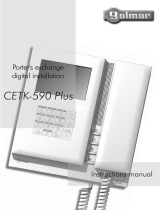
Permits placement of a CETK-590 Plus porter's exchange between
the door panel and the telephones, making typical functions of this
porter´s exchange possible: Capture calls from the door panel,
receive and make calls to apartments, transfer calls from the
door panel to apartments, save unanswered calls to apartments
in the memory, etc..
Installation diagram on pages 39-40.
Lock release
VISTA PLUS door panel
5
22
Porter's
exchange CD-PLUS/R5
FA-PLUS/C
Tekna R5 monitors
4
3+coax
2
Lock release
VISTA PLUS door panel
2 2
To other door panels
4
Max. 120 apartments
FA-PLUS/CFA-PLUS/C
3SAFETY PRECAUTIONS
OInstall or modify the equipment without the power connected.
OThe installation and handling of these equipments must be performed by authorised personnel.
OThe entire installation must be at least 40 cm. away from any other installation.
ODo not use excessive force when tightening the connector screws.
OInstall the unit in a dry and protected place without risk of drip or water projections.
OAvoid to place it near to heating sources, dusty locations or humid enviroments.
ODo not block ventilation holes of the unit so that air can circulate freely.
OTo avoid damage, the converter has to be firmly fixed.
5
5
5
5
ancel
?
!
.
-
,
a bc 2 def3
jkl5
mno6
pqrs7 tuv8 wxyz9
+-0x*
ghi4

22
1
5
9
2
6
0
3
7
C
4
8
22
1
5
9
2
6
0
3
7
C
4
8
5
2 2
CD-PLUS/R5
2
CD-PLUS/R5
2
2 2
3 + coax
3 + coax
5
3 + coax
44
3 + coax
FA-PLUS/C FA-PLUS/C
FA-PLUS/CFA-PLUS/C
FA-PLUS/C FA-PLUS/C
*
ancel
?
!
.
-
,
a bc 2 def3
jkl5
mno6
pqrs7 tuv8 wxyz9
+-0x*
ghi4
5
5
5
5
5
5
5
5
2
FA-PLUS/C
* *
CD-PLUS/R5
2
22
1
5
9
2
6
0
3
7
C
4
8
3 + coax
5
5
5
5
5
3 + coax
FA-PLUS/C
FA-PLUS/C
ancel
?
!
.
-
,
a bc 2 def3
jkl5
mno6
pqrs7 tuv8 wxyz9
+-0x*
ghi4
FA-PLUS/C
2
4
OPERATION MODES
Backbone encoder (general door panels)
Permits Plus general door panels with VISTA PLUS inner portals, allowing placement of a CETK-590
Plus porter's exchange between both elements as an option.
This type of installation requires a converter for each inner backbone.
Installation diagram on pages 41-42.
Plus general door panel Backbone 0
Porter's
exchange
To the rest of
the backbones
Lock release
VISTA PLUS door panel
Lock release Lock release
Plus general door panel
Lock release
VISTA PLUS door panel
Backbone encoder (Coded door panel)
This variation from the previous mode, permits installation of
Plus coded door panels with VISTA PLUS monitors, simply by
varying the converter's position, moving it to the door panel's
output.
A porter's exchange can also be placed before the converter
or a VISTA PLUS door panel between the converter and the
monitors as options.
This variation can be applied with or without general door
panels.
Installation diagram on pages 43-44.
Plus coded door panel
Lock release
Porter's
exchange
Backbone 1
Tekna R5 monitors
Backbone 2
Tekna R5 monitors
Tekna R5 monitors
Max. 120 apartments
Max. 120 apartments
Max. 200 apartments
Terms:
Backbone
Riser: Physical cabling of the installation
in the same backbone (logical address).
: Logical address.
*

escription of the converter.
D
DIN rail latch release
Autodiagnostic LEDs
Configuration dip switch
PLUS connection block
R5 connection block
5
escription of the converter.
D
DESCRIPTION
INSTALLATION
DIN rail latch release
Autodiagnostic LEDs
Configuration dip switch
PLUS connection block
R5 connection block
Detail of the converter installation.
The converter can be installed on a DIN guide
(6 elements), pressing it lightly.
To extract the converter from the DIN guide,
use a plain screwdriver to lever the flange as
shown in the picture.DIN 46277
Install the converter in a dry and protected place free from the risk of drip or water projections.
To avoid damage the converter must be firmly fixed.
Install or modify the equipment without the power
connected.
The installation and handling of this equipment must be
by authorised personnelperformed .
To install the converter directly on the wall, drill two holes of
Ø6mm. and insert the wallplugs. Fix the converter with
the specified screws.

e
Dscription of the configuration dip switch.
The SW1 configuration dip switch is located in the upper
right part of the module.
Backbone encoder (Master):
Activate this mode if you have PLUS door panels before the converter and
VISTA PLUS monitors (without door panel) after the converter (see page
35).
Loads the VISTA PLUS installation with a
communications resistor.
Set to ON position only if you do not have
the VISTA PLUS door panel in the building
or backbone.
*Factory default
Set to ON to program the column.
This function should only be used if the module is being used as
backbone encoder (see page 35).
Once the programming progress is finished return the switch to
OFF position.
The programming steps are described on page 38.
The operation mode of the converter is defined according to the dip switch 2 and 3
combinations:
Backbone encoder (Slave):
Activate this mode if you have PLUS door panels before the converter and
VISTA PLUS monitors and door panels after the converter. (See page 35).
Exchange interface:
Activate this mode if placing a PLUS porter's exchange in a VISTA PLUS
installation (see page 34).
e
Dscription of the configuration jumpers.
Auto
On
On
Off
Off
Off
JP1
JP2
JP4
End of line resistor (Only in porter´s exchange interface mode).
Set to AUTO if the porter's exchange is connected through a D4L-R5 or
D4L-R5R video distributor (recommended), if doing without this element,
set to the OFF position.
End of line resistor (Only in backbone encoder mode).
Set to Off in all converters except the last one (end of the coaxial cable).
To be handled exclusively by Golmar personnel.
Set always to Off.
6
CONFIGURATION
e
Dscription of the configuration dip switch.

7AUTODIAGNOSTIC LEDS
e
Dscription of autodiagnostic LEDs.
The autodiagnostic LEDs are placed next to
the configuration dip switch.
Fixed: Programming error, go through the steps from the
beginning.
Off: Correct operation.
Red LED
Green LED
Fixed: Correct operation.
Slow blinking: Programming activated.
Quick blinking: Programming finished.
PROGRAMMING
r
Pogramming the converter.
The converter must be programmed with a backbone code (see page ), which must be different for
each converter, following the steps set out below 35
.
Access the door panel programming mode, pressing
the key button followed by the installer secret code
(factory default 1315), just as indicated in the
door panel manual.
Introduce the column code to program, followed by three
zeros, then press the bell button.
O.K.
0 0 01
Activate the converter programming by setting the dip switch
number 4 to ON.
The door panel will emit a tone and the green LED
on the converter will begin to slow blinking, indicating
that programming has begun.
To indicate that the equipment has been correctly
programmed, the door panel will emit a tone and the
green LED on the converter will begin to quick blinking,
indicating that programming has begun.
Exit programming by setting the dip switch number 4 to OFF
and pressing the C button on the door panel.
If there are more converters, repeat the previous steps introducing a different backbone code for
each of them.
If during one of these processes the red LED on the converter switches on, restart programming from
the beginning.

R. Line R. Line
Take off JP1 jumper of
all the distributors except
in the last one.
Main
Main
INSTALLATION DIAGRAMS
Porter's exchange interface mode with D4L-R5 distributor.
8
A/D
+_
Vi+ Vi-
Tekna R5
RCTK
EL500/R5
VO-VO+VI+VI-A/D
+
CN1
+
--- CV1 +12
CV2
_
SA
+
D4L-R5
_
_
+
D/A
-V
+V
SALIDA
CN2
CN4
SPL. OUT 4SPL. OUT 3
CN3
_
_
+
D/A
-V
+V
ENTRADA
CN1
_
_
+
+
D/A
D/A
VD4-
VD3-
VD4+
VD3+
SPL. OUT 2SPL. OUT 1
_
_
+
+
D/A
D/A
VD2-
VD1-
VD2+
VD1+
A/D
+_
Vi+ Vi-
_
SA
+
CD-PLUS/R5
VCE GND + +
D Ax Ay Vin GNDVout
+A/D
GND Vin+ Vin- Vout+ Vout-
D4L-R5
_
_
+
D/A
-V
+V
SALIDA
CN2
CN4
SPL. OUT 4SPL. OUT 3
CN3
_
_
+
D/A
-V
+V
ENTRADA
CN1
_
_
+
+
D/A
D/A
VD4-
VD3-
VD4+
VD3+
SPL. OUT 2SPL. OUT 1
_
_
+
+
D/A
D/A
VD2-
VD1-
VD2+
VD1+
JP
1 2
PLUS BUS
R5 BUS
+
-
230 110 0
-
+
SEC
PRI
FA- PLUS/C
ver. 938072
+
-
230 110 0
-
+
SEC
PRI
FA- PLUS/C
ver. 938072
Vista Plus Door Panel
CETK-590 Plus
A
+_D
Malla
Vin Vout CTO
ancel
?
!
.
-
,
a bc 2 def3
jkl5
mno6
pqrs7 tuv8 wxyz9
+-0x*
ghi4
CN3
SW2
Tekna R5
RCTK
MM
M
JP1
JP1
*
*
*
= Master.
= Slave.
M
S

9
EL500/R5
VO-VO+VI+VI-A/D
+
CN1
+
--- CV1 +12
CV2
Take off JP1 jumper of
all the distributors except
in the last one.
CD-PLUS/R5
VCE GND + +
D Ax Ay Vin GNDVout
+A/D
GND Vin+ Vin- Vout+ Vout-
JP
1 2
PLUS BUS
R5 BUS
+
-
230 110 0
-
+
SEC
PRI
Main
Main
FA- PLUS/C
ver. 938072
+
-
230 110 0
-
+
SEC
PRI
FA- PLUS/C
ver. 938072
Vista Plus Door Panel
CETK-590 Plus
A
+_D
Malla
Vin Vout CTO
ancel
?
!
.
-
,
a bc 2 def3
jkl5
mno6
pqrs7 tuv8 wxyz9
+-0x*
ghi4
CN3
SW2
JP1
D4L-R5R
+
+
__
+
+
__
+
_
Vout
VD1 VD2
+
_
Vin
+
_
VD3VD4
A/D
+
_
Junction Box
A/D
+
_
_
A/D
+
_
Junction Box
A/D
_
JP1
D4L-R5R
+
+
__
+
+
__
+
_
Vout
VD1 VD2
+
_
Vin
+
_
VD3VD4
A/D
+_
Vi+ Vi-
Tekna R5
RCTK
R. Line
_
SA
+
A/D
+_
Vi+ Vi-
Tekna R5
RCTK
R. Line
_
SA
+
*
*
*
Porter's exchange interface mode with D4L-R5R distributor.
M M
= Master.
= Slave.
M
S
M
INSTALLATION DIAGRAMS

10
ackbone encoder mode (general door panels)
B
V
out-
V
out+
MALLA
V
in+
V
in-
A
in
A
out
D
+
-
CV
+
CV
-
General door panel
Communication R. : ACTIVATED
CD-PLUS/R5
+A/DGND MP VP Vout+ Vout-
EL500/R5
VO-VO+VI+VI-A/D
+
CN1
+
--- CV1 +12
CV2
JP
1 2
PLUS-BUS
R5-BUS
Backbone 1
VCE GND + +
D Ax Ay Vin GNDVout
*
1
4
7
2
5
8
3
6 0
9
C
1
4
7
2
5
8
0
CANCEL
O.K.
3
6
9
*General door panel
STADIO
INOX
ROCK
INSTALLATION DIAGRAMS
Main
FA-PLUS/C
rev.938072
+
-
230 110 0
-
+
SEC
PRI
Main
FA-PLUS/C
rev.938072
+
-
230 110 0
-
+
SEC
PRI
Main
FA-PLUS/C
rev.938072
+
-
230 110 0
-
+
SEC
PRI
M
Vista Plus Door Panel
M
S

11 INSTALLATION DIAGRAMS
To the next
door panel/s
V
out-
V
out+
MALLA
V
in+
V
in-
A
in
A
out
D
+
-
CV
+
CV
-
General door panel
Communication R.: DEACTIVATED
CD-PLUS/R5
+A/DGND MP VP Vout+ Vout-
EL500/R5
VO-VO+VI+VI-A/D
+
CN1
+
--- CV1 +12
CV2
JP
1 2
R5-BUS
R5-BUS
Backbone 250
VCE GND + +
D Ax Ay Vin GNDVout
*
FA-PLUS/C
rev.938072
+
-
230 110 0
-
+
SEC
PRI
Main
Main
FA-PLUS/C
rev.938072
+
-
230 110 0
-
+
SEC
PRI
Main
FA-PLUS/C
rev.938072
+
-
230 110 0
-
+
SEC
PRI
M =Master.
S =Slave.
S
Vista Plus Door Panel
M
S
Backbone 0

R. Line R. Line
Take off JP1 jumper of
all the distributors except
in the last one.
PLUS-BUS
R5-BUS
Main
Coded panel
Communication R.: ACTIVATED
ackbone
B encoder mode (coded panel) with D4L-R5 distributor.
INSTALLATION DIAGRAMS
Coded panel
Main
M =Master.
S =Slave.
M
12
A/D
+_
Vi+ Vi-
_
SA
+
D4L-R5
_
_
+
D/A
-V
+V
SALIDA
CN2
CN4
SPL. OUT 4SPL. OUT 3
CN3
_
_
+
D/A
-V
+V
ENTRADA
CN1
_
_
+
+
D/A
D/A
VD4-
VD3-
VD4+
VD3+
SPL. OUT 2SPL. OUT 1
_
_
+
+
D/A
D/A
VD2-
VD1-
VD2+
VD1+
A/D
+_
Vi+ Vi-
_
SA
+
CD-PLUS/R5
+A/D
GND Vin+ Vin- Vout+ Vout-
V
out-
V
out+
MALLA
V
in+
V
in-
A
in
A
out
D
+
-
CV
+
CV
-
VCE GND + +
D Ax Ay Vin GNDVout
JP
1 2
1
4
7
2
5
8
3
6 0
9
C
1
4
7
2
5
8
0
CANCEL
O.K.
3
6
9
*
STADIO
INOX
ROCK
*
+
-
230 110 0
-
+
SEC
PRI
FA- PLUS/C
ver. 938072
+
-
230 110 0
-
+
SEC
PRI
FA- PLUS/C
ver. 938072
Tekna R5
RCTK Tekna R5
RCTK
M
JP1
M M

13 INSTALLATION DIAGRAMS
CD-PLUS/R5
+A/D
GND Vin+ Vin- Vout+ Vout-
PLUS BUS
R5 BUS
V
out-
V
out+
MALLA
V
in+
V
in-
A
in
A
out
D
+
-
CV
+
CV
-
VCE GND + +
D Ax Ay Vin GNDVout
JP
1 2
1
4
7
2
5
8
3
6 0
9
C
1
4
7
2
5
8
0
CANCEL
O.K.
3
6
9
*Coded Panel
STADIO
INOX
ROCK
+
-
230 110 0
-
+
SEC
PRI
Main
FA- PLUS/C
ver. 938072
+
-
230 110 0
-
+
SEC
PRI
Main
FA- PLUS/C
ver. 938072
JP1
D4L-R5R
+
+
__
+
+
__
+
_
Vout
VD1 VD2
+
_
Vin
+
_
VD3VD4
A/D
+
_
Junction Box
A/D
+
_
A/D
+_
Vi+ Vi-
Tekna R5
RCTK
R. Line
_
SA
+
A/D
+_
Vi+ Vi-
Tekna R5
RCTK
R. Line
_
SA
+
ackbone
B encoder mode (coded panel) with D4L-R5R distributor.
M
M
M M
Coded panel
Communication R.: ACTIVATED
*
Take off JP1 jumper of
all the distributors except
in the last one.
M =Master.
S =Slave.

TROUBLESHOOTING HINTS
Porter's exchange interface mode
The porter's exchange don't receive calls from the door panel.
Check if it can receive calls from any other monitor (pressing the lock release button, with the
handset off the hook)
If so, check in the porter´s exchange configuration that the option capture door panel is
activated and that the door panel has dip switch number 6 set to ON
If not, check that the porter´s exchange is not off, see
Also check the connections (page 39-40) and configuration (page 37) of the converter.
The image does not show in the porter´s exchange.
Remember that images are only shown from calls made from door panels with camera.
Check that the voltage between the ' - ' and '+' terminals of the distributor is from 17.5 to
18.5Vc.c., if not, check the power supply and its connections.
Check that you have used the correct output of the converter for the coaxial cable (VCE and
GND) and that the number 2 dip switch is OFF and number 3 is ON.
Backbone encoder mode (General door panels)
Calls cannot be made from the general door panels.
Check if calls can be made from the inner door panels.
I f yes, make sure you have correctly programmed the backbone in the converters (page 38)
and revise the connections (page 41-42) and configuration (page 37) of the converters,
remember set to ON the number 1 dip switch only if you do not have the VISTA PLUS
door panel in the building or backbone.
If not, revise the monitor's programming (see door panel manual) and program it again if
necessary.
Check that the voltage between the ' - ' and '+' terminals of the different elements is from 17.5
to 18.5Vc.c., if not, check the power supply and its connections.
No image is shown when receiving calls from the general door panels.
Remember that images are only shown from calls made from door panels with camera.
Check that the correct inputs and outputs have been used for this type of installation (see
diagram on page 41-42), that the number 2 dip switch is ON and number 3 is OFF and
that only the end of line resistor (JP2) of the last converter is activated.
The converter cannot be programmed.
Check that the coded panel is in configuration mode before setting the number 4 dip switch
to ON (see page 37) and that the programming steps are correctly followed.
Check that 'A/D' terminal is not shortcircuited with other terminals.
Backbone encoder mode (Coded panel)
Calls cannot be made.
Remember that the system remains inactive for 45 seconds after connecting the power
supply, the same occurs upon connecting any unit to the installation.
Make sure that the converter does not have any backbone programmed. To do this set dip
switch number 2 to the OFF position and number 3 to the ON position, then set them
again to the correct position (2 in ON and 3 in OFF), this resets the backbone
programming.
Revise the converter connections (page 43-44) and configuration (page 37), remember set
to ON the number 1 dip switch only if you do not have the VISTA PLUS door panel in the
building or backbone.
Check that the voltage between the ' - ' and '+' terminals of the different elements is from 17.5
to 18.5Vc.c., if not, check the power supply and its connections.
O
w
w
w
w
O
w
w
w
O
w
w
w
w
O
w
w
O
w
w
O
w
w
w
w
On-Off light indicator.
14

O
w
w
Any mode
O
w
w
w
O
w
O
w
No image is shown when receiving calls from the door panel.
Remember that images are only shown from calls made from door panels with camera.
Check that the correct converter input and output have been used for this type of installation
(see diagram on page 43-44), that the dip switches are in the correct position (2 in ON and
3 in OFF) and that the end of line resistor (JP2) is activated.
Nothing operates.
Remember that the system remains inactive for 45 seconds after connecting the power supply,
the same occurs upon connecting any unit to the installation.
Check the output power supply voltage between ' - ' and '+' terminals: it should have 17,5 to
18,5Vd.c. If not, disconnect the power supply from the installation and measure again. If it's
correct now, it means there is a short circuit in the installation: disconnect the power supply
from mains and check the installation.
Check that 'A/D' terminal is not shortcircuited with ' - ' or '+' terminals.
Continuous audio feedback.
Check that 'A/D' terminal is not shortcircuited with other terminals.
There is no sound
Check that you have used the correct terminals (see diagrams on pages 39 to 44).
TROUBLESHOOTING HINTS
15
1095 Budapest, Mester utca 34.
Tel.: *218-5542, 215-9771, 215-7550,
216-7017, 216-7018 Fax: 218-5542
Mobil: 30 940-1970, 30 959-0930
www.golmar.hu
1141 Budapest, Fogarasi út 77.
Tel.: *220-7940, 220-7814, 220-7959,
220-8881, 364-3428 Fax: 220-7940
Mobil: 30 531-5454, 30 939-9989
/
