Page is loading ...

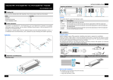
Right side
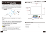
Panel diagram
Please follow installation steps as below:
Please check the following items before installation, if anything missing, please contact the
dealer .
PoE Ethernet repeater 1PCS
User Manusal 1PCS
1) Turn off the power of all the related devices before the installation, otherwise the device
would be damaged;
2) Check if the Ethernet cable and other cables are connected correctly;
3) Connect the PoE IN port of and PoE Switch by Ethernet cable; PoE Ethernet repeater
4) Connect the PoE OUT port of and PoE IP Camera by Ethernet cable;POE Ethernet repeater
5) Check if the installation is correct and device is good, make sure all the connection is reliable
and then power up the system;
6) Make sure the network and PoE transmission are working.
Installation steps
PoE Ethernet Repeater
User Manusal
12
PoE Ethernet Repeater
VerB 1.1
The PoE Ethernet extender can transmit Ethernet signal and power through one single
network cable, which solve the transmission distance limitation of devices as for network
camera and so on. The product supports IEEE802.3u 100Base-TX and IEEE802.3 af/at
standards. The Max power consumption transmission can up to 30 watts, which can supply
25.4 watts power consumption for terminal devices. The product can extend to 100M and
thus the cascading distance can up to 400m after be cascaded for several times. And it can
support 100Mbps full duplex transmission mode with good protection ability of anti-ESD
and anti-surge. The special design of built-in splicing slot on both sides and magnetic
attraction as well as hanger on the bottom enables multiple installation methods of wall-
mounting, splicing and adsorption. Above all, the product can give a better systematic
solution of transmission distance and power supplying for network camera and other device.
Features
Each can repeat Ethernet and power signal to 100m and cascade connection up to 400m;
Support IEEE 802.3u,100Base-TX standard and IEEE 802.3 af/at PoE standard;
Real-time, 0 time-delay, with no-store & forward technology;
Superior ESD and surge protection ability;
Plug and play, no software and agreement transformation necessary;
Built-in splicing slot, with magnet and hanger, unique and integrated design, wall-mounted、
splicing and adsoption installations available, which suits in all kinds of engineering
installation.
Left side Top view
IP camera
LCD
Diaplay
NVR
IP camera
PoE Switch
PoE Repeater PoE Repeater
PoE Repeater
Cat5e/6
Cat5e/6
Application
Notice
1) Please use standard Cat5e/6 cable to reach the longest transmission distance;
2) Please make sure the transmission directivity of PoE is correct.
1) The photo Top view 's "PoE IN" and "PoE OUT" indicate the PoE transmission direction;
2) The photo Right side’s “PoE LED indication” is yellow LED for PoE status; and “Data
indication” is green LED data connection. Different LED status have different means. Green
LED lasting ON: Data connection is OK. Green LED out: Data connection is fail. Green LED
flick: Data connection and transmission is OK.
3) The photo Left side’s LED function is same as the photo Right side.
PoE OUT PoE IN
PoE
Data PoE
Data

连接接口
Specification
PoE Ethernet Repeater
4
100m
3
200m
P o E S w i t c h
300m
30W
20.86W 16.03W 10.26W
0m
IP Camera
Telephone
400m
7.5W
IP Camera
Diagram I
Distributive relation between power consumption and transmission distance
Network cable collating
The network cable can be embed
through the splicing slot under space
Network cable
The network cable can be embed
through the splicing slot under space
Product are subject to change without prior notice
Installation method
1.Wall-Mounting type 2.Splicing type (Optional component, you
need to buy them if necessary)
3.Magnetic attraction type
Magnetic attraction
at both bottom sides.
Splicing direction
连接接口
Troubleshooting
连接接口
If any trouble in installation, please follow these steps:
连接接口
Please make sure you have followed the instruction to install the device;
Please confirm if the RJ45 cable order is in accordance with the EIA/TIA568A or 568B
industry standards;
The transmission distance depends on the signal source and cable quality, please do
not exceed the maximum transmission distance;
Please replace a failure device with a proper one to check if the device is broken;
If the problem still exists, please contact the dealer.
PoE Ethernet Repeater
Item
Description
Power
Power Supply
PoE
Consumption
< 3 Watt
Network
Port
Port
PoE IN:100Mbps、PoE In port
PoE OUT:100Mbps、PoE Output port
Transmission distance
Max: 400m
(Please reference to the diagram I to distinguish the relation
between power consumption and transmission distance)
Media
Cat5e/6
PoE standard
Supports IEEE802.3af、IEEE802.3at standards
PoE Power supply
Media-span and End-span
Ethernet
Exchange
Standard
IEEE802.3u 100BASE-TX
Delay
<20us
Status
Indicator LED
PoE IN port and PoE OUT port:
RJ 45 Yellow LED indicate PoE status;
Green LED indicate Ethernet status.
Protection
ESD
Lever III 1a Contact Discharge
Lever III 1b Air Discharge
Per:IEC61000-4-2
Surge Protection
Lever III Per:IEC61000-4-5
Environment
Working Temperature
-10℃~55℃
Storage Temperature
-40℃~85℃
Humidity
0~95%
Mechanical
Size(L×W×H)
113mm×45.5mm×29mm
Material
ABS
Color
Black
Weight(Gross)
58g
IP Camera
/


