Page is loading ...

Installation 00-02-0478 page 1 of 28
Millennium Controller MC Series
Installation and Operation Manual
For Kernel 0.96
Description
MC Series Millennium Controller is a PC-based monitoring, control and
data acquisition system. Designed with engine-driven compressors in
mind, the MC Series is suitable for a wide range of industrial applica-
tions. As the heart of the control package, the MC series continuously
monitors inputs and set points for correct operation. When an out-of-limit
event occurs, the controller provides an alphanumeric readout of critical
machinery data or shutdown fault information.
In addition to the shutdown and control functions, the MC series con-
troller provides both local and remote communications of vital equip-
ment and operating data. This advanced system offers multiple options
for remote communications. A serial link is provided for Programmable
Logic Controllers, PC’s and SCADA systems. Radio and satellite com-
munications are accommodated through the MODBUS RTU protocol.
Operations analysis and maintenance is facilitated by the operation hours
and data trending system. The shutdown snapshot feature gives operators
a complete picture of system conditions at shutdown.
Basic Components
Controller Display PC Modules (head)
MCH-L-M: 586 compatible processor, 100 MHz; 8 MB RAM,
LCD Display.
MCH-V-M: 586 compatible processor, 100 MHz; 8 MB RAM;
VFD Display.
Power Supply
MCPS-NA: no analog outputs.
MCPS-A1: one analog output.
MCPS-A2: two analog outputs.
Optional I/O Expansion Modules
C267 Module
UL/cUL Listed, Class I, Div. 2 Groups C & D
The C267 adds standard I/O capability to the Murphy Millennium
Controllers via MODBUS RTU communication. The C267 includes 8
digi-
tal inputs, 7 analog inputs, power supply monitor, 8 discrete outputs and 1 fre-
quency input for speed sensing.
C277 Module
UL/cUL Listed, Class I, Div. 2 Groups C & D
The C277 adds temperature sensing capabilities to the Murphy Millennium
Controllers through MODBUS RTU communications via an RS485 port.
The C277 can read up to 1
8 ungrounded thermocouples or mA sources from
pressure transmitters and other transmitters.
C287 Module
UL/cUL Listed, Class I, Div. 2 Groups C & D
The C287 adds precision analog inputs and additional analog outputs to
the Murphy Millennium Controllers via Modbus RTU communica-
tions. The C287 includes
four 15-bit analog inputs, four 16-bit analog out-
puts (all 4-20mA).
Optional Hold Up Capacitor Package
MCCP Model
The MCCP module is an optional Hold Up Capacitor Package that allows
the MC Series Millennium Controller to work flawlessly with 12 VDC
cranking battery systems.
MC Series General Specifications
NOTE: The system is intended for mounting in a weatherproof enclosure.
Power Input: 10-32 VDC, 26 watts maximum.
Operating Temp.: -40 to 85°C (-40 to185°F)
Base Unit w/
VFD Display: -40 to 85°C (-40 to 185°F).
Base Unit w/
LCD Display:
-20 to 70
°
C (-4 to 158
°
F).
Programming: PC-based Ladder Logic.
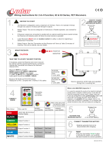
Please read the following information before installing. A visual inspection of this product for damage during shipping is recommended
before mounting. It is your responsibility to have a qualified person install this unit and make sure it conforms to NEC and local codes.
GENERAL INFORMATION
C US
WARNING
BEFORE BEGINNING INSTALLATION OF THIS MURPHY PRODUCT
✔✔
Disconnect all electrical power to the machine.
✔✔
Make sure the machine cannot operate during installation.
✔✔
Follow all safety warnings of the machine manufacturer.
✔✔
Read and follow all installation instructions.
Approved
Class I, Div. 2
Groups C & D
00-02-0478
Revised 02-07
Section 50

Installation 00-02-0478 page 2 of 28
Display Module Specifications
MCH-L-M Controller Display Module:
- 586 compatible microprocessor, includes 8 MB of RAM.
- 4-lines with 20 characters each, liquid crystal display.
- 16-key user interface: set point entry, alarm acknowledgement, start, stop,
reset, etc.
- 4 RS485 serial ports: power supply, serial I/O, modbus slave, spare.
- 2 RS232 for ladder logic programming/monitoring or remote communications.
- 8 MB DISKONCHIP
®
for increased data storage capability.
MCH-V-M Controller Display Module:
- 586 compatible microprocessor and includes 8 MB of RAM.
- 4-lines with 20 characters, vacuum fluorescent display.
- 16-key user interface: set point entry, alarm acknowledgement, start, stop,
reset etc.
- 4 RS-485 serial ports: power supply, serial I/O, modbus slave, spare.
- 2 RS-232 for ladder logic programming/monitoring or remote communications.
- 8 MB DISKONCHIP
®
for increased data storage capability.
MCPS-A1; MCPS-A2 and MCPS-NA
Power Supplies Specifications
- 16 Optically Isolated DC Digital Inputs (NO or NC), sink or source, LED
indicators, external power supply, or board supplied power, jumper selectable.
Approved for use with general purpose passive mechanical switches in
Division 2 hazardous areas.
- Open Circuit max. 32VDC, I short circuit max 9.2 mA.
- Open Circuit min. 10VDC, I short circuit min 2.5 mA.
- Scan Time 100 ms.
- 1 Magnetic Pickup Input/AC Run Signal: 45 to 10kHz. 5 VAC rms min.
120 VAC rms max.
- 4 Solid State Relay Outputs: External power must be supplied; 32 VDC
max to 5.5 VDC min; I max 3A; short circuit and thermally protected; 100
ms scan time. Inductance 1 H max. @ 0.25 A, 5 mH max. @ 3A.
- 4 Mechanical Relay Outputs: Form "C" contacts:
Rating: 10 A 125 VAC, 6 A 250 VAC, 1/8 HP 125, 250 VAC,
5 A 30 VDC 100 ms scan time. Approved for Div. 2.
- 2 4-20mA Outputs: 1-10 and/or 1-14 bit resolution (depending on model
used) max. loop resistance RL = (Vps – 3.15) / 0.02 Ω.
- 1 Digital Potentiometer Output: 0-255 steps, 50K-Ohms,
27.5 µW max., (other values of resistance available).
- 1 RS-485 Serial Port, Modbus RTU Slave 38.4 KBaud, half duplex.
- MCPS-NA Power Supply
: No analog outputs
- MCPS-A1 Power Supply
: One analog output (14 bit).
- MCPS-A2 Power Supply
: Two analog outputs
Expansion Modules Specifications
C267 -
8 Digital Inputs - 7 Analog Inputs - 8 Digital outputs
Input Voltage: 9 to 28 VDC, 2.25 – 11 watts not including maximum
18 amps for outputs.
Operating Temperature: -22 to 158 °F (-30 to 70 °C).
Storage Temperature: -22 to 158 °F (-30 to 70 °C).
Communications: 1 – RS-485 9600-N-8-1 Communication port.
Connection is made via modular RJ45 Jack. There are two jacks for sim-
ple connection to other Comm Series Modules. The user can plug from
the master controller into the C267. A second cable can then be run
from the other jack to the next Comm Series Module. This can be
repeated until the customers I/O resources are satisfied. The last module
in the line must have a terminating resistor installed in the second jack
(available from Murphy as part number 00005292).
Digital Inputs: 8 Optically isolated inputs (positive voltage or ground).
Approved for use with general purpose passive mechanical switches in
Division 2 hazardous areas.
Analog Inputs: 7 - 8-bit. Each analog individually shunt selectable for
0-5 VDC, end of line 4-20 ma, or resistive sending unit.
Frequency Input: 1 - Optically isolated frequency input requiring 3
VAC rms up to 100 Hz and 2 VAC rms above 100 Hz. Used for speed
reference. Range: 60 - 10,000 Hz.
Outputs: 8 - FET Outputs rated at 5A with a total current draw through
the unit not to exceed 18A when both PWR2 pins are connected.
C277 -
18 Analog Inputs
Input Voltage: 9 to 28 VDC, 0.6 watts.
Operating Temperature: -22 to 158 °F (-30 to 70 °C).
Storage Temperature: -22 to 158 °F (-30 to 70 °C).
Communications: 1 – RS-485 9600-N-8-1 Communication port.
Connection is made via modular RJ45 Jack. The C277 has two jacks to
simplify connection to the Millennium controller. Typically, a connec-
tion is made in one jack and out the other. If the device is at the end of
the communications loop, a terminating resistor must be installed in the
second jack (available as part number 00005292).
Inputs: 18 - can be configured to
ungrounded
read thermocouples or
end-of-line 0-24 mA (4-20 mA) signals. 0.01 mA resolution.
Type J: -150 to 750°C (-238 to 1382°F). 0.1 C (0.2 F) resolution.
Type K: -150 to 1180°C (-238 to 2156°F). 0.1 C (0.2 F) resolution.
Type E: -150 to 638°C (-238 to 1180°F). 0.1 C (0.2 F) resolution.
Type T: -150 to 400°C (-238 to 752°F). 0.1 C (0.2 F) resolution.
C287 -
4 Analog Inputs - 4 Analog Outputs
Input Voltage: 9 to 28 VDC, 3 – 5 watts including 4-20 mA outputs.
Operating Temperature: -22 to 158 °F (-30 to 70 °C).
Storage Temperature: -22 to 158 °F (-30 to 70 °C).
Communications: 1 – RS-485 9600-N-8-1 Communication port.
Connection is made via modular RJ45 Jack. There are two jacks for sim-
ple connection to other Comm Series Modules. The user can plug from
the master controller into the C287. A second cable can then be run
from the other jack to the next Comm Series Module. This can be
repeated until the customers I/O resources are satisfied. The last module
in the line must have a terminating resistor installed in the second jack
(available as part number 00005292).
Analog Inputs: 4 - 15-bit true 0-20 mA.
Analog Outputs: 4 - 16 bit analogs, software configurable to 0-24 mA,
0-20 mA, or 4-20 mA.
Specifications
continued

Installation 00-02-0478 page 3 of 28
Display Module Mounting Dimensions
5.50 in.
(140 mm)
0.156 in. (4 mm)
dia. 4 places
5.50 in. (140 mm)
Panel
Mounting
Hole
Keps
Nut
Screw
6-1/2 in. (165 mm)
49/64 in. (19 mm)
6-1/2 in.
(165 mm)
3 in.
(76 mm)
5/16 in. (8 mm)
5-1/4 in.
(133 mm)
6.0 in.
(152 mm)
3.0 in.
(76 mm)
3.0 in.
(76 mm)
6.0 in. (152.3 mm)
Mounting Hole
HOME Fn
7
4
1
+/-
8
5
2
0
9
6
3
ESC
ACK
AUTO
MAN
SETUP
ENTER
RESET
STEP
RUN
STOP
PAGE
DOWN
TEST
TIMER
“O”
PAGE
SETUP
4-1/2 in.
(114 mm
clearance)
4-1/2 in.
(114 mm
clearance)
COM3 RS-232
MODEM NOT
ALL MODELS
COM2 RS-232
SERIAL CONSOLE
OR MODEM
COM1 RS-232
DEBUG/DOWNLOAD
CONSOLE
RS-485
COMB I/O
EXPANSION
B A SHD
COMA POWER
CONTROL
RS-485
COMCD
MODBUS
RTU SLAVE
B A SHD
RS-485
COMCD
SPARE
PORT
B A SHD
Allow 4-1/2 in. (114 mm)
for Plug and cable bends radius
bottom and left side from back.
Each Dsub-9 protudes
1/16 in. (1.5 mm)
NOTE: Use maximum blade width 5/64 in. (2 mm)
screwdriver for wire terminals in these plugs.
Fastening screws for flanges require 1/8 in. (3 mm).
blade screwdriver which can be used for all
other screw terminals.
Side View
Back View
Mounting Hole
Side View
Front View
WWAARRNNIINNGG::
PERFORM THE MOUNTING OPERATION WITH POWER SOURCE OFF. THE MILLENNIUM CONTROLLER MODULE WAS
DESIGNED TO BE MOUNTED WITHIN A WEATHERPROOF ENCLOSURE. IT IS INTENDED FOR MOUNTING IN A FLAT PANEL. INSERT
THE MODULE FROM THE FRONT SIDE OF THE PANEL AND SECURE THE FOUR MOUNTING SCREWS AND NUTS THROUGH THE

Installation 00-02-0478 page 4 of 28
Power Supply Mounting Dimensions
C267, C277, C287 Mounting
MCCP Mounting
Power Supply (Rail mount type.)
Mounting
Rail
*
Mounting
Bracket
To Panel
The Power Supply has (3) three rail mount clamps for easy panel mounting. Mounting rail is NOT supplied.
Standard DIN mounting rail models: DIN 46277, EN50035, and EN50022 zinc–plated steel recommended.
Recommended length for the mounting rail: 12 inches (305 mm) minimum.
Power
Supply
BRACKET DETAIL
TS8
TS6
TS2
K4 K3 K2 K1
TS4
A
B
CH
GND
+
JS1
TS1
NEG
POS
POS
NEG
POS
NEG
POS
JS2
GND
-+ -++- ++-+- ++- - - +- ++- -
SSR4
SSR3SSR2SSR1
_
SSR2
SSR1
_
+
+
SSR4SSR3
+
_
_
+
NC3
C2NO2
NC1
C1
NO1
C3
NO3
NC2
NC4
C4
NO4
TS7
SHG
B1
A1
W1
+4- 20
SHG
-4-20
+4- 20
SHG
-4-20
TS5
+
-
-+-
+- +-
+
_
1
2
3
4
5
6
7
89
10
11
12
13
14
1516
4- 20mA
current
sour ce
4- 20mA
current
sour ce
JR-1
NEG
TS3
MPU
SHG
4-1/4 in.
(108 mm)
13 in. (330 mm)
Mounting
Rail*
Mounting
Bracket
3-1/2 in.
(89 mm)
Clearance for Mounting
Rail and Cables 6 in. (152 mm)
NOTE: The maximum
screwdriver blade width
for wire terminals for
plugs TS4 & TS8 is
5/64 in. (2 mm).
Mounting flange screws
and other terminal block
screws use 1/8 in. (3 mm)
wide screwdriver blade.
NOTE: Mount the MCPS
power supply horizontally.
If vertical mounting is
required, DIN rail clamps
must be used to secure the
MCPS on the vertical DIN rail.
7 in.
(178 mm)
4-11/16 in.
(119 mm)
3/4 in.
(19 mm)
8-1/2 in.
(216 mm)
Mounting
Holes
5/32 in.
dia.
(3 mm)
2-pls.
4-1/2 in. (114 mm)
5-3/4 in.
(147 mm)
7-1/4 in.
(184 mm)
# 8-32 x 1/2 in.
(13 mm) slotted
pan head (2-screws)
are supplied with
the bracket.
Drill and tap for
#8-32 use lock
washers or
locking nuts.
3-1/2 in.
(89 mm) dia.
Side View
Front View
Front View
WWAARRNNIINNGG::
PERFORM THE MOUNTING OPERATION WITH POWER SOURCE OFF. THE MILLENNIUM CONTROLLER POWER
SUPPLY WAS DESIGNED TO BE MOUNTED ON A FLAT PANEL AND WITHIN A WEATHERPROOF ENCLOSURE.
Side View
Side View

Installation 00-02-0478 page 5 of 28
HOME
MILLENNIUM CONTROLLER
Fn
7
4
1
+/-
8
5
2
0
9
6
3
ESC
ACK
AUTO
MAN
SETUP
ENTER
RESET
STEP
RUN
STOP
PAGE
DOWN
TEST
TIMER
“O”
PAGE
UP
HOME
7
key
➡➡
4
key
➡➡
2
key
STEP
5
key
➡➡
8
key
Fn key
ESC/ACK key
SETUP/ENTER key
TIMER“0” key
PAGE DOWN
3
key
TEST key
6
key
PAGE UP
9
key
AUTO/MAN
1
key
RUN/STOP
0
key
RESET
±
key
➡➡
MC Series Display Module Features and functions
1 2 3 4 5 6 8 9 10 11 12 13 14 15 16 17 18 19 207
21 22 23 24 25 26 28 29 30 31 32 33 34 35 36 37 38 39 4027
41 42 43 44 45 46 48 49 50 51 52 53 54 55 56 57 58 59 6047
61 62 63 64 65 66 68 69 70 71 72 73 74 75 76 77 78 79 8067
ST: Normal operation
RPM=xxx HRS=xx,xxx.x
Ps=xx.x Pd1=xxx
Pd2=xxx Pd =xxx
ANALOG OUTPUTS
ANALOG1 0
ANALOG2 0
DIGITAL POT 0
The Alphanumeric Display (All Models)
The Millennium Controller Display is divided into lines and pages. Up to 100 pages are
available in the main displays, setup pages and event pages. Each page can have up to
32 lines. The last page displaying data will be the end page for that display or menu.
It does not necessarily have to be the 100th page.
The same rule applies to the lines of text displayed. The last line displaying data will
be the end line (it does not necessarily have to be the 32nd line).
The Control Module (Head)
The Display/Communications and Control Module or head contains the
processing power in the form of a single board computer with support
board Vacuum Fluorescent Display (VFD), or optional Liquid Crystal
Display (LCD), both of which are dot matrix alphanumeric displays in a 4-
line by 20 character format, and 16-key keypad, emulating a combination
of the ten-key pad of a personal computer and a traditional gas compres-
sor panel annunciator.
Next Page to
the Left
Last Page
Pressing
Typical 1st Page or Home Page
Typical Last Page
+
Fn
HOME
7
Next Page
to the Right
6
4
=
=
=

Installation 00-02-0478 page 6 of 28
MC Series Display Module Features and Functions
MC Series Display Module Keys Description
1 2 3 4 5 6 8 9 10 11 12 13 14 15 16 17 18 19 207
21 22 23 24 25 26 28 29 30 31 32 33 34 35 36 37 38 39 4027
41 42 43 44 45 46 48 49 50 51 52 53 54 55 56 57 58 59 6047
61 62 63 64 65 66 68 69 70 71 72 73 74 75 76 77 78 79 8067
Ps =34.5 Pd1=104
Pd =xxx
T1 =xxx T2 =xxx
EXHAUST TEMPERATURES
CYL 1=xxx CYL 2=xxx
ENG COOLANT xxxF
COMP COOLANT xxxF
*EXTERNAL ROD LOAD*
CYL1 C=xxxxx T=xxxxx
CYL2 C=xxxxx T=xxxxx
Suction Pressure:
8.0 PSI
The Page Up key allows the user
to navigate to the top of the dis-
played page, 4 lines at a time.
The Page Down key allows the user
to navigate to the bottom of the dis-
played page, 4 lines at a time.
NOTE: The display shows only 4 lines of text at a given page.
9
PAGE
UP
3
PAGE
DOWN
The keys are used to enter numbers while an edit session is active. All key presses can be processed by the application, as defined by the programmer, in addi-
tion to their default functions. When the cursor is off, the first key press of any display navigation key will not result in any action except to turn the cursor on.
Any key used in controller program function will immediately cause the function on any press of the key. Examples: Reset, Run/Stop, Test, and Timer “0”.
This key has a modified action relative to the current location of the cursor and current page being displayed. Each keypress responds as follows:
— The display changes to show the top 4 lines of the current page. If already shown then it will change the page to the home page for that menu.
— The page is changed to display the Home Page of the ‘main’ menu.
When the Fn Key is pressed before the Home key, the page is changed to display the last page of the current menu.
The page is changed to display the previous page of the current menu. If no previous page exists, the key will be ignored.
This key does nothing at the Home page.
The page is changed to display the next page of the current menu. If no next page exists, the key will be ignored.
The next page is defined while creating the displays in MDesigner. This key moves to the right from the direction of the Home page.
Navigates the cursor position up, line by line, each key press. If the cursor is positioned at the top of the display, each key press will shift the display
down by one line to display a new top line. If the cursor is placed on the top line of the page, the key will be ignored.
When the Fn Key is pressed before the Arrow Up key, the Autoscroll feature is activated. When Autoscroll is ON, the display will
periodically be shifted up, by one line, to display a new bottom line. The period is controlled by the scroll time for each page.
When the last line of the page has been displayed, the display will be reset to the first line of the page and begin again.
Navigates the cursor position down, line by line, each keypress. If the cursor is positioned at the bottom of the display, each keypress will cause the
display to be shifted up, by one line, to display a new bottom line. If the cursor is positioned on the last line of the page, the key will be ignored.
When the Fn Key is pressed before the Arrow Down key, the Autoscroll feature is deactivated. When Autoscroll is OFF, the display is no
longer changed automatically.
Fn
4
6
8
Fn
HOME
7
Pressing
The Up key allows the user to
navigate to the top of the dis-
played page, 1 line at a time.
8
Pressing
The Down key allows the user to
navigate to the bottom of the dis-
played page, 1 line at a time.
2
Pressing
Fn
2

Installation 00-02-0478 page 7 of 28
Navigates the cursor position up, by four lines, each keypress. The display will be replaced with previous four lines of the page being dis-
played. If less than four lines are available to be displayed, the cursor will be positioned at the top line of the page. If the cursor is positioned
on the top line of the page, the key will be ignored.
Navigates the cursor position down, by four lines, each keypress. The display will be replaced with the next four lines of the page being dis-
played. If less than four lines are available to be displayed, the cursor will be positioned at the last line of the page.
If the cursor is positioned on the last line of the page, the key will be ignored.
This key has a modified action relative to the current location of the cursor and the current page being displayed.
Each keypress responds as follows:
— When an edit session is active, it is canceled. Any changes made will be discarded.
— When an active event is displayed, if the current login has sufficient rights, the displayed event will be acknowledged.
This key has a modified action relative to the current location of the cursor and the current page being displayed.
Each keypress responds as follows:
— When the cursor is positioned on a line that has been designed to allow editing and the current login has sufficient rights,
an edit session is activated. The cursor moves from the left to the right side and is placed on top of the parameter to be changed.
— When an edit session is active, any changes made will be validated and the controller will be updated if the changes are valid,
otherwise they are discarded. The edit session will be ended in either case. The cursor is moved from the right, back to the left side.
— When the cursor is positioned on a line that has been designed to navigate to other menus and the current login has
sufficient rights to enter the menu, the display will change to show the menu.
When the Fn Key is pressed before the Setup/Enter key, SETUP menu is displayed. If this is done while in the settings, nothing happens.
Use this key to create a combination of keypresses to activate special operations. After the Fn key has been pressed, the top line reads “Fn key activat-
ed” and while this is displayed, the second key of the combination can be pressed. The length of time is the “Notify Message Delay” in the administra-
tor settings. If the time expires, the next keypress will operate normally. The primary keys to follow the Fn key are: Home, Setup/Enter.
This key can be assigned by the programmer, for the application running in the controller. Example:
— The AUTO/MAN key can function as a toggle for the mode of operation in the controller application.
— AUTO/MAN is an abbreviation for AUTOmatic/MANual.
This key can be programmed for the application running in the controller. Example: The STEP key can function as a single STEP command
for the MANual mode. When the controller is in MANual mode, the STEP key can advance the sequence once for each time it is pressed. If
a sequence has finished, it will remain idle until the STEP key is pressed again, to advance it.
This key has a modified action relative to the current location of the cursor and page displayed. When pressed the RESET key resets a shut-
down. It is also used to reset Class B1 and B2 and Test Timers.
When the cursor is positioned on a line that is displaying a timer and the current login has sufficient rights, the accumulator for the timer is
reset each time the key is pressed, in effect restarting the timer at its preset. With the cursor anywhere except on the B1, B2 and Test Timer
line, the function is the same as the TTDJ; if the Test Timer is active, it will reset, otherwise the B1 and B2 timers will reset.
This key can be programmed for the application running in the controller. Example: Pressing the key will initiate the start (RUN) sequence.
Pressing the key again, initiates the shutdown (STOP) sequence. This key is active from any display with one exception. The numeric function
key 0 (zero) is active during an edit. Therefore, the operator must exit from the edit session (ESC), to operate the key normally.
This key can be assigned by the programmer, for the application running in the controller. Example: Pressing this key will initiate the TEST mode.
Once the TEST mode is activated, the TEST key can be pressed again, to end the mode.
This key has a modified action relative to the current location of the cursor and page displayed. Each keypress responds as follows:
— When the cursor is positioned on a line that is displaying a timer and the current login has sufficient rights, the accumulator
for the timer is set to zero, in effect ending the timer as if it had timed out normally. With the cursor anywhere except on the B1, B2, or
the Test Timer lines, the function is the same as the TTDJ; if the Test Timer is active, it will be zeroed. Otherwise if the B1 and
B2 Timers are active, first the B1 Timer is zeroed and next the B2 Timer is zeroed.
— When an edit session is active, any changes made will be removed, clearing and restarting the session, which remains activated.
MC Series Display Module Key Descriptions
continued
9
PAGE
UP
3
PAGE
DOWN
ESC
ACK
SETUP
ENTER
Fn
Fn
1
AUTO
MAN
5
STEP
+/-
RESET
0
RUN
STOP
TEST
TIMER
“O”

Installation 00-02-0478 page 8 of 28
MC Series I/O Matrix
C267 8 7 8 11
C267NOAI 15 8 11
C277 18
C287 44
MCPS 16 4 4 2 1
4X C277 72
MCPS 16 4 4 2 1
4X C267 32 28 32 4 4
4XC267NOAI 60 32 4 4
MCPS 16 4 4 2 1
4X C287 16 16
MCPS 16 4 4 2 1
3X C277 54
C267 8811
C267NOAI 15 8 11
MCPS 16 4 4 2 1
3X C277 54
C287 44
MCPS 16 4 4 2 1
3X C267 24 21 24 3 3
3XC267NOAI 45 24 3 3
C287 44
3X C267 16 4 4 2 1
3X C267 24 21 24 3 3
3XC267NOAI 45 24 3 3
C277 18
3X C267 16 4 4 2 1
3X C287 12 12
C277 18
MCPS 16 4 4 2 1
3X C287 12 12
C267 8 7 8 11
C267NOAI 15 8 11
MCPS 16 4 4 2 1
2X C277 36
2X C267 16 14 16 2 2
2XC267NOAI 30 16 2 2
MCPS 16 4 4 2 1
2X C277 36
C287 88
MCPS 16 4 4 2 1
2X C267
16 14 16 2 2
2XC267NOAI 30 16 2 2
2X C287 36
MCPS 16 4 4 2 1
2X C277 36
C287 44
C267 8 7 8 11
C267NOAI 15 8 11
MCPS 16 4 4 2 1
C277 18
C287 44
2XC267 16 14 16 2 2
2XC267NOAI 30 16 2 2
MCPS 16 4 4 2 1
C277 18
2X C287 88
C267 8 7 8 11
C267NOAI 15 8 11
MCPS 16 4 4 2 1
DI
4-20mA/0-5 VDC/
Sender/ DI
4-20mA/
TC/ AI
4-20mA AI
FET DO
Relay DO
4-20mA
AO
Freq.
IN
PS
Mon

C267 Expansion Module Components
A.
Status LED’s: There are four Status LED’s on the C267.
- COMM stands for Communication. It will flash any time a communication packet passes to or from the C267.
- COP stands for Controller Operating Properly. It will flash every quarter second if the internal CPU is functioning
properly. This light should start flashing as soon as power is supplied to the PWR1 connection.
- PWR1 stands for Power 1. This light will turn on when power is properly applied to the Pins PWR1 and GND.
This is the control power.
- PWR2 stands for Power 2. This light will turn on when power is properly applied to the PWR2 and GND pins.
This is the battery plus power for the FET outputs. Note: Both PWR2 pins should be connected to increase the
amperage capability of the outputs.
B.
RS-485 Communication Port: Port A and Port B are electrically common, for wiring convenience. If more than
one module is used, you can bring your patch cable into Port A and then connect from Port B to the next module.
Note: The last module in the communication chain must have a terminating resistor module.
C.
Power 2: This is the battery plus power for the FET outputs. Note: Both PWR2 pins should be connected to increase
the amperage capability of the outputs.
D.
Output Connections: OUT1 through OUT8 are the controller output connections. Each output supplies battery plus
at 5 amps. Please note: The maximum current draw for the unit is 18 amps when both PWR2 pins are connected.
E.
Control Power 1: Connect PWR1 to battery (+) and GRD to battery (-). This supplies power to the control portion
of the circuitry.
F.
Frequency Input: This input is used to sense frequency via a magnetic pickup.
G.
Digital Inputs: IN1 through IN8 are optically isolated digital inputs for use with ground or battery plus digital
switches.
H.
Analog Inputs: AN1 through AN7 are 8-bit analog inputs that can be shunt selected to read 0-5 VDC, 4-20 mA,
and/or resistive electric gauge sending units. Each analog can be individually selected for any one of the three types
of inputs.
I.
Analog Selector Shunts: These shunts are used to configure what type of end device is being used to supply the ana-
log signal for each analog channel. To select 4-20 mA, place the shunt on top two pins. To select electric gauge
sending unit, place the shunt on the bottom two pins. To select 0-5 VDC, remove the shunt from the channel.
J.
Modbus Address Select Shunts: These shunts allow you to assign a unique address to each C267 that may be in the
system. This allows the master controller to differentiate between the modules. For example, to name the controller
address 21, place the shunts on LK1, LK4, and LK16 (1 + 4 +16 = 21).
Installation 00-02-0478 page 9 of 28
B
C267
M
o
d
e
l
(0004923)
RS485
Port A
PWR1COMM
COP
PWR2 PWR2
OUT 1 OUT 2
OUT 3 OUT 4
OUT 5 OUT 6
OUT 7
SNDR 4 - 20
AN 1
AN 2
AN 3
AN 4
AN 5
AN 6
GRD
HZ
IN 1
IN 3
IN 5
IN 7
AN 1
AN 2
AN 4
AN 6
AN 3
AN 5
AN 7
IN 2
IN 4
IN 6
IN 8
PWR1
OUT 8
PWR2
Address
1
2
4
8
16
32
RS485
Port B
A J C D
E
F G H I
C267 Model Expansion Module
8 Discrete Inputs - 7 Analog Inputs - 8 Discrete Outputs - 1 Frequency Input

C277 Expansion Module Components
POWER UP NOTE: Due to the high accuracy of the readings provided by the C277, a great deal of averaging
will be processed at power-on. If all 18 channels are active, up to 48 seconds are needed to reach full accuracy.
Delay configuring or polling the C277 for 8 seconds on power-up. Once this initial power-up sequence is com-
plete, each complete update takes about 2 seconds with a filter frequency of 120.
A.
Status LED’s: There are four Status LED’s on the C277.
- COMM stands for Communication. It will flash any time a communication packet passes to or from the C277.
- COP stands for Controller Operating Properly. It will flash every quarter second if the internal CPU is function-
ing properly. This light should start flashing as soon as power is supplied to the PWR1 connection.
- PWR1 stands for Power 1. This light will turn on when power is properly applied to the Pins PWR1 and GND.
This is the control power.
- PWR2 stands for Power 2. This light will turn on when the internal (minus) 5 VDC supply is functioning properly.
B.
RS-485 Communication Port: Port A, Port B and Port C are electrically common, for wiring convenience. If
more than one module is used, you can bring your patch cable into Port A and then connect from Port B to the
next module. Port C is available for twisted pair cable connections.
Note: The last module in the communication chain must have a terminating resistor module.
C.
Modbus Address Select Shunts: These shunts allow you to assign a unique address to each C277 that may be in
the system. This allows the master controller to differentiate between the modules. For example, to name the con-
troller address 21, place the shunts on LK1, LK4, and LK16 (1+4+16 = 21).
D.
Control Power Terminals: Hook battery (+) to the terminal labeled B+. Hook battery (-) to terminal labeled B-.
E.
Channel Connection Terminals: Each channel has two dedicated terminals. The top row is the negative side of
the connection and the bottom row is the positive side of the connection.
C277 Model (0007620)
RS485
Port A
PWR1COMM
COP
C277
COMM
Series
AN 1+
AN 2+
AN 3+
AN 4+
AN 5+
AN 6+
AN 7+
AN 8+
AN 9+
AN 10+
AN 11+
AN 12+
AN 13+
AN 14+
AN 15+
AN 16+
AN 17+
AN 18+
(-)
(-)
(-)
(-)
(-)
(-)
(-)
(-)
(-)
(-)
(-)
(-)
(-)
(-)
(-)
(-)
(-)
(-)
B+
B–
PWR2
Address
1
2
4
8
16
32
RS485
Port B
RS485
Port C
A B C D
E
A–
B+
Installation 00-02-0478 page 10 of 28
C277 Model Expansion Module
18 Thermocouples or 4 - 20 mA Inputs

Installation 00-02-0478 page 11 of 28
C287 Designation
A.
Status LED’s: There are four Status LED’s on the C287.
- COMM stands for Communication. It will flash any time a communication packet passes to or from the C287.
- COP stands for Controller Operating Properly. It will flash every half-second if the internal CPU is functioning
properly. This light should start flashing as soon as power is supplied to the PWR connection.
- PWR1 stands for Power 1. This light will turn on when power is properly applied to the Pins PWR1 and GND. This
is the control power.
- PWR2 stands for Power 2. This light will turn on when the internal +/- 15 VDC power is functioning properly.
B.
RS-485 Communication Port: Port A and Port B are electrically common, for wiring convenience. If more than
one module is used, you can bring your patch cable into Port A and then connect from Port B to the next module.
Note: The last module in the communication chain must have a terminating resistor module.
C.
Modbus Address Select Shunts: These shunts allow you to assign a unique address to each C287 that may be in
the system. This allows the master controller to differentiate between the modules. For example, to name the
controller address 21, place the shunts on LK1, LK4, and LK16 (1 + 4 +16 = 21).
D.
Control Power: Hook battery (+) to PWR and battery (-) to GND. This supplies power to unit.
E.
Analog Loop Power: Hook the analog Loop Power to this input.
F.
Analog Outputs: These pins supply the 4-20 mA output current.
G.
Analog Inputs: When used as the last unit on an analog loop, ground the AN(-) pin and hook the output from the
transmitter to the AN(+) pin. When used in a loop, bring the output from the transmitter into the AN(+) pin and
come out of the AN(-) pin to the next device.
RS485
Port A
PWR1COMM
COP
GND PWR
AO 1
AO 3AO 2
AO 4
AI 1+
AI 1–
AI 2+
AI 2–
AI 3+
AI 3–
AI 4+
AI 4–
LPWR
PWR2
Address
1
2
4
8
16
32
RS485
Port B
A B C
D
E F G
C287 Model (0005945)
C287 Model Expansion Module
4 Analog Inputs - 4 Analog Outputs

Installation 00-02-0478 page 12 of 28
Typical MCPS Power Supply Wiring Diagram
WARNING
EXPLOSION HAZARD - DO NOT
DISCONNECT EQUIPMENT UNLESS
POWER HAS BEEN SWITCHED OFF
OR THE AREA IS KNOWN TO BE
NON-HAZARDOUS.
NOTES
Field Wiring connections to be installed in accordance with the NEC
for Class I, Div. 2, Grps. C ad D Hazardous Locations.
Install separate conductors for SSR and controller power input.
Allow for coductor voltage drop when determining conductor size.
All power supplies must have common ground.
For an inductive load, install a diode in parallel with the load.
Use a fast recovery 3A, 50 PIV diode. Mount diode as close as
possible to the load device. maximum load inductance: 1H @ 0.25A, 5mH @ 3A.
Rl = (Vps - 3.15)/0.20
Rl = Loop Resistance
Vps = Power Supply Volts
Sensor Switch Input Current: 2.45 MA max @ 10VDC, 9.2MA @32VDC
Minimum charge/discharge cycle time 5 min.
1.
2.
3.
4.
5.
6.
MCCA72
RS485 Serial
I/O ComA
Future Expansion Port
Separate
signal wiring
from power
wiring
Separate speed signal
wiring from other wiring
10A, 125VAC, 5A,30VDC Typical
for All Four relay Outputs
Maximum
Load 3A
Power Supply
NON-INCENDIVE FIELD WIRING CONNECTIONS
TO PASSIVE SWITCHES FOR USE IN CL. I,
DIV. 2 GPS. C AND D HAZARDOUS LOCATIONS.
ROUTE SWITCH LEADS SEPARATE
FROM ALL OTHER WIRING.
Stored Energy Source (MCCP) See Note 6.
SSR Power
Supply Leads
Power
Supply
10-32 VDC
Typical Normally
Open Sensor for
Use in Cl. I, Div. 2
Grps. C and D
Hazardous Locations
Typical Normally
Closed Sensor for
Use in Cl. I, Div. 2
Grps. C and D
Hazardous Locations
Maximum
Load 3A
Power
Inputs
Ring Gear
Magnetic Pickup
CHGND
TS8
TS6
TS1
JS1
JS2
TS2
TS3
123 45 678 9
AN2 OUT
AN1 OUT
OUT 8
OUT 7
OUT 6
OUT 5
OUT 4
OUT 3
OUT 2
OUT 1
10 11 12 13 14 15 16
TS7
K4
K3
K2 K1
TS4
A
B
CH
GND
+-+ -++- ++-+- ++- - - +- ++- -
_
_
+
+
+
_
_
+
TS5
+
-
-+-
+- +-
+
_
I/P
I/P
GOV
MPU
SHG
LOAD
MAXIMUM
LOAD 3A
NEG
JR-1
4-20mA
4-20
4-20
4-20
4-20
SHG
SHG
SHG
B1
W1
A1
Current
Source
4-20mA
Current
Source
87
654321
910111213141516
NEG
NEG
NEG
SSR1 SSR2 SSR3 SSR4 NO1
C1 NC1
NO2
C2 NC2
NO3
C3 NC3
NO4
C4 NC4
SSR1 SSR2 SSR3 SSR4
POS
POS
POS
GND
NC
NEG
POS
6A
6A
NEG
POS
3A
NO COM
COM
NEG
NEG
NEG
NEG
POS
POS
POS
POS
POS
MAXIMUM
LOAD 3A
3
4
_
+
_
+
_
+
*
*
Use shielded twisted pair wire for speed signal
and analog outputs. Connect the shield drain wire
at only one end.
*

Installation 00-02-0478 page 13 of 28
RS485 Serial
I/O ComA
10A, 125VAC, 5A,30VDC
Typical for All Four relay Outputs
Maximum
Load 3A
WARNING
EXPLOSION HAZARD - DO NOT
DISCONNECT EQUIPMENT UNLESS
POWER HAS BEEN SWITCHED OFF
OR THE AREA IS KNOWN TO BE
NON-HAZARDOUS.
Display Module
Power
Supply
Expansion
Module
NON-INCENDIVE FIELD
WIRING CONNECTIONS TO
PASSIVE SWITCHES FOR
USE IN CL. I, DIV. 2 GPS. C
AND D HAZARDOUS
LOCATIONS.
ROUTE SWITCH LEADS
SEPERATE
FROM ALL OTHER WIRING.
Use Belden 9841 or
120 ohm characteristic
impedance cable
for RS485 connections.
Stored Energy Source (MCCP)
See Note 6.
SSR Power
Supply Leads
Power Supply
10-32 VDC
Typical Normally
Open Sensor for
Use in Cl. I, Div. 2
Grps. C and D
Hazardous Locations
Typical Normally
Closed Sensor for
Use in Cl. I, Div. 2
Grps. C and D
Hazardous Locations
Maximum
Load 3A
Power
Inputs
MCCA72
Cable Assembly
NOTES
Field Wiring connections to be installed in accordance with
the NEC for Class I, Div. 2, Grps. C ad D Hazardous Locations.
Install separate conductors for SSR and controller power input.
Allow for coductor voltage drop when determining conductor size.
All power supplies must have common ground.
For an inductive load, install a diode in parallel with the load.
Use a fast recovery 3A, 50 PIV diode. Mount diode as close as
possible to the load device.
Maximum load inductance: 1H @ 0.25A, 5mH @ 3A.
Rl = (Vps - 3.15)/0.20
Rl = Loop Resistance
Vps = Power Supply Volts
Sensor Switch Input Current: 2.45 MA max @ 10VDC, 9.2MA @32VDC
Minimum charge/discharge cycle time 5 min.
1.
2.
3.
4.
5.
6.
Ring Gear
Magnetic
Pickup
CHGND
TS8
TS6
TS1
JS1
JS2
TS2
TS3
TS7
TS4
A
B
CH
GND
+-+ -++- ++-+- ++- - - +- ++- -
_
_
+
+
+
_
_
+
TS5
+
-
-+-
+- +-
+
_
I/P
I/P
GOV
MPU
SHG
RJ45 Cable
(00004925)
Terminating Resistor
Module (00005292)
Vertical mounting is suggested -
Harnesses are available
LOAD
MAXIMUM
LOAD 3A
NEG
JR-1
4-20mA
4-20
4-20
4-20
4-20
SHG
SHG
SHG
B1
W1
A1
Current
Source
4-20mA
Current
Source
87
654321
910111213141516
NEG
NEG
NEG
SSR1 SSR2 SSR3 SSR4 NO1
C1 NC1
NO2
C2 NC2
NO3
C3 NC3
NO4
C4 NC4
SSR1 SSR2 SSR3 SSR4
POS
POS
POS
GND
NC
NEG
POS
6A
6A
NEG
POS
3A
NO COM
COM
NEG
NEG
NEG
NEG
POS
POS
POS
POS
POS
MAXIMUM
LOAD 3A
3
COM3 RS-232
MODEM NOT
ALL MODELS
COM2 RS-232
SERIAL CONSOLE
OR MODEM
COM1 RS-232
DEBUG/DOWNLOAD
CONSOLE
RS-485
COMB I/O
EXPANSION
B A SHD
COMA POWER
CONTROL
RS-485
COMC
MODBUS
RTU SLAVE
B A SHD
RS-485
COMD
SPARE
PORT
B A SHD
4
RS485
Port A
PWR1COMM
COP
C277
COMM
Series
AN 1+
AN 2+
AN 3+
AN 4+
AN 5+
AN 6+
AN 7+
AN 8+
AN 9+
AN 10+
AN 11+
AN 12+
AN 13+
AN 14+
AN 15+
AN 16+
AN 17+
AN 18+
(-)
(-)
(-)
(-)
(-)
(-)
(-)
(-)
(-)
(-)
(-)
(-)
(-)
(-)
(-)
(-)
(-)
(-)
B+
B–
PWR2
Address
1
2
4
8
16
32
RS485
Port B
RS485
Port C
A–
B+
123 45 678 9
AN2 OUT
AN1 OUT
OUT 8
OUT 7
OUT 6
OUT 5
OUT 4
OUT 3
OUT 2
OUT 1
10 11 12 13 14 15 16
K4
K3
K2 K1
Typical Millennium Controller System Layout

Installation 00-02-0478 page 14 of 28
RJ45 Cable (00004925)
C267 wiring.eps
Ring Gear
Magnetic Pickup
To "B+"
Expansion Module
C267 Model (0004923)
To I/O Expansion
COMB "B" port on
MCH module
(00005292)
- Vertical mounting is suggested - Harnesses are available.
- Use Molex crimp pins 39000039 (Murphy 00007181).
- Use crimper specifically designed for these Molex pins.
- Separate signal wiring from power and output wiring.
- Use shielded twisted pair cable for 4-20 mA/Transmitter/
Speed signal wiring.
- Connect shield drain wire to ground of the device reading
the signal, only.
Separate speed signal
wiring from other wiring
= Screw terminal block
NOTE:
RS485
Port A
PWR1COMM
COP
PWR2 PWR2
OUT 1 OUT 2
OUT 3 OUT 4
OUT 5 OUT 6
OUT 7
SNDR 4 - 20
AN 1
AN 2
AN 3
AN 4
AN 5
AN 6
GRD
HZ
IN 1
IN 3
IN 5
IN 7
AN 1
AN 2
AN 4
AN 6
AN 3
AN 5
AN 7
IN 2
IN 4
IN 6
IN 8
PWR1
PXMSPXMS
PXMS
PXMS
PXMS
PXMS
PXMS
OUT 8
PWR2
Address
1
2
4
8
16
32
RS485
Port B
Typical C267 Module Wiring

RJ45 Cable
(00004925)
Cable Assembly
(00007197)
SIGNALS POWER & OUTPUTS
Cable Assembly
(00007196)
Expansion Module C267 Model (0004923)
To Interface Module C267TBIF (0007719)
To I/O Expansion
COMB "B" port on
MCH module
(00005292)
Vertical mounting is suggested -
Harnesses are available
Magnetic
Pickup
Ring Gear
PXMS
NOTE:
RS485
Port A
PWR1COMM
COP
PWR2 PWR2
OUT 1 OUT 2
OUT 3 OUT 4
OUT 5 OUT 6
OUT 7
SNDR 4 - 20
AN 1
AN 2
AN 3
AN 4
AN 5
AN 6
GRD
HZ
IN 1
IN 3
IN 5
IN 7
AN 1
AN 2
AN 4
AN 6
AN 3
AN 5
AN 7
LK1
F-GND/
XMTR V+
Signal
Shield
Freq. IN
AI 1
AI 2
AI 3
AI 4
AI 5
AI 6
AI 7
DI 1
DI 2
DI 3
DI 4
DI 5
DI 6
DI 7
DI 8
DO 1
DO 2
DO 3
DO 4
DO 5
DO 6
DO 7
DO 8
IN 2
IN 4
IN 6
IN 8
PWR1
GRD
HZ
IN 1
IN 3
IN 5
IN 7
AN 1
AN 2
AN 4
BCD Port
DI Top Row V+/GND (LK1)
DI Btm Row SW. IN
DO Top Row Switched V+
DO Btm Row GND
AN 6
AN 3
AN 5
AN 7
IN 2
IN 4
IN 6
IN 8
PWR1
OUT 8
PWR2 PWR2
BAT –
BAT +
OUT 1 OUT 2
OUT 3 OUT 4
OUT 5 OUT 6
OUT 7 OUT 8
PWR2
Address
1
2
4
8
16
32
RS485
Port B
C267TBIF
(0007719)
C267 Model
(0004923)
Use shielded twisted pair
cable with shielded
drain wire connected
at the EMSTBIF end only.
*
*
*
Typical C267 Module Wiring Using C267TBIF
Installation 00-02-0478 page 15 of 28

Installation 00-02-0478 page 16 of 28
RJ45 Cable
(00004925)
Expansion Module
C277 Model (0007620)
To I/O Expansion
COMB "B" port on
MCH module
(00005292)
Only shielded, thermocouple grade, thermocouple extension
wire should be used. The shield ground (drain wire)
should be grounded at the readout instrument.
No dissimilar metals should be used to make
splices in this wire. For type J and K
thermocouples (-) is color coded red.
Type J (+) is white, and type K (+) is yellow.
For other types consult a thermocouple reference book.
Pressure transmitters should be wired using shielded
twisted pair cabling.
Do not use grounded thermocouples.
For best accuracy group thermocouple
inputs from the middle channels, 9 and 10.
Locate 4 - 20 mA channels at the first
and last channels.
Vertical mounting is suggested -
Harnesses are available
PXMS
PXMS
PXMS
PXMS
NOTE:
See NOTE
below
B+
W
W
W
W
W
W
W
R
R
W
R
W
W
W
R
R
R
R
R
R
R
R
= Screw terminal block
RS485
Port A
PWR1COMM
COP
C277
COMM
Series
AN 1+
AN 2+
AN 3+
AN 4+
AN 5+
AN 6+
AN 7+
AN 8+
AN 9+
AN 10+
AN 11+
AN 12+
AN 13+
AN 14+
AN 15+
AN 16+
AN 17+
AN 18+
B+
B–
PWR2
Address
1
2
4
8
16
32
RS485
Port B
RS485
Port C
A–
B+
Typical C277 Module Wiring

Installation 00-02-0478 page 17 of 28
RJ45 Cable
(00004925)
Expansion Module
C287 Model (0005945)
B+
To I/O Expansion
COMB "B" port on
MCH module
(00005292)
Vertical mounting is suggested
PXMS
PXMS
PXMS
PXMS
I/P
I/P
I/P
I/P
RS485
Port A
PWR1COMM
COP
GND PWR
AO 1
AO 3AO 2
AO 4
AI 1+
AI 1–
AI 2+
AI 2–
AI 3+
AI 3–
AI 4+
AI 4–
LPWR
PWR2
Address
1
2
4
8
16
32
RS485
Port B
- Vertical mounting is suggested - Harnesses are available.
- Use Molex crimp pins 39000039 (Murphy 00007181).
- Use crimper specifically designed for these Molex pins.
- Use shielded twisted pair cable for 4-20 mA/Transmitter/any Analog Input & Output.
= Screw terminal block
NOTE:
Typical C287 Module Wiring

Installation 00-02-0478 page 18 of 28
MCH Module Basic Instructions
Turn power on to the MCPS power supply. After approximately 20
seconds the first display appears. The following screens are “typical”.
Actual screens depend on the program used by the controller.
Press HOME key To Get to The Home Screen
May need to pressed more than once, depending on cursor position.
To Start the Unit ( from HOME SCREEN)
Press "RESET" then "RUN STOP". The display below will be
shown and the unit will proceed to the Warmup mode.
To Reset a Shutdown
To reset a shutdown condition press "RESET". The display
below shows a typical shutdown screen. To leave these screens,
press a navigation key. If more than one shutdown occurs, the
display will cycle displaying the Events (1 of 2, etc.).
To See Class B1, B2 &Test Timers press "RIGHT Arrow Key"
To Reset Class B1 Timer in Timer Screen
Use “DOWN” key to get to the B1 TIMER line. Press “RESET”.
To Zero Class B1 Timer in Timer Screen
With Cursor on B1 Timer line, Press "TIMER "0".
To Reset Class B2 Timer in Timer Screen
Use “DOWN” key to move to the B2 TIMER line.
Press "RESET" key.
To Zero Class B2 Timer in Timer Screen
With Cursor on B2 Timer line, Press "TIMER "0".
Alteratively, from any screen, pressing the"RESET" key will
reset both the B1 and B2 Timers. With both Timers active, one
press of "TIMER "0" will zero the B1 Timer and the next press of
"TIMER "0" will zero the B2 Timer. Also, from any screen the
"TEST MODE" can be initiated and the "TEST" timer zeroed.
To Enter Test Mode Press "TEST" key.
To View Test Timer Seconds Left
From the Home screen, press "RIGHT ARROW" to get to the
Timer Screen and view the Test Timer Value.
To Reset and Zero Test Timer in Timer Screen
Move Cursor down to Test Timer line and press the "RESET"
key. The Test Timer will be reset to a standard value of
300 seconds. Press the TIMER "0" key to zero the test timer.
Press "RESET" to reset a shutdown while in Test.
Millennium Controller Basic Instructions
ST: READY TO START
RPM= 0 HRS= 0.0
Ps = 0.0 Pd1= 0
Pd2= 0
ST: START COMMITTED
RPM= 0 HRS= 0.0
Ps = 0.0 Pd1= 0
Pd2= 0
Event 1 of 1
02:01:52PM 04JAN01
Shtdn: 1st Discharge
Hi Scrubber Liq LvL.
ST: READY TO START
RPM= 0 HRS= 0.0
Ps = 0.0 Pd1= 0
Pd2= 0
ST: Running
10/19/01 B1= 0sec
18:58 B2= 0sec
Test:Off Test=300sec
ST: Running
10/19/01 B1= 0sec
18:58 B2= 0sec
Test:Off Test=300sec
ST: Running
10/19/01 B1= 0sec
18:58 B2= 600sec
Test:Off Test=300sec
ST: Running
10/19/01 B1= 0sec
18:58 B2= 0sec
Test:Off Test=300sec
ST: Running
10/19/01 B1= 0sec
18:58 B2= 0sec
Test:On Test=298sec
ST: Running
10/19/01 B1= 0sec
18:58 B2= 0sec
Test:Off Test=300sec
ST: Running
10/19/01 B1= 300sec
18:58 B2= 0sec
Test:Off Test=300sec

Installation 00-02-0478 page 19 of 28
Definitions
Application – A program written with ISaGRAF that does the functional
control that is downloaded to the Millennium Controller using a PC and the
ISaGRAF software.
Project
– The result of MDesigner screen creation and configuration soft-
ware which is downloaded using MDesigner software.
Login
– The line that has this is the line where different levels of privileges are
granted based on the pass code used, and the resulting Login level. Login level (5)
does not require a code, and is the level when there is not a higher level Login pre-
sent. To Login with a higher level code, the cursor must be placed on this line, and
then the ENTER key must be pressed. The cursor will move over the zero dis-
played on the right side of that line. A code can now be entered. There are (4) levels
of code, going from level (4), the lowest level of privilege up to level (1), the high-
est level of privilege. Level (1) is called the Administrator level, and the privileges
are all encompassing. There is nothing that cannot be done with the Administrator
code. The lower levels have different privileges. For example, level (4), some set-
tings are available to be changed that cannot cause improper operation of the
machinery. Level (3) is a level where there should be set points that could cause
improper operation of the machine, and not everybody should have access to those.
Level (2) is a level where calibration of inputs can be done, and is for higher level
trained technicians. At the Administrator level, level (1), the Project, and /or
Application can be deleted, outputs can be forced off and on, a Remote Debugger
can be run, the administrator menu is available, and the real time clock can be set.
All login levels have a common timer that starts to count down after each key press.
If there are no key presses for the length of the Inactive/AutoLogout Delay, then the
Login level will revert back to level (5).
MCH Module Power Up and Self Test
Turn on the power to the MCPS power supply. There will be about 20 sec-
onds before the display first shows:
The above screen will be present for about 6 seconds after initial power-up
and boot-up. If SETUP is pressed and there is an application and project
present, the Setup screen will be shown as:
If there is no application or project, the "Login" line and the two "Remove"
lines will be missing. If there is no application, but there is a project, only
the "Remove Application" line will be missing. If there is no project, but
there is an application, only the "Remove Project" line will be missing.
If SETUP is not pressed and there is no project, or no project and no appli-
cation, this screen will show next:
Pressing ESC / ACK (Escape) will go back to the Setup Menu to allow
Setup Menu selections, such as "Enable Transfer".
If SETUP is not pressed and there is a project, but no application, this screen
will show:
This screen will be the only screen available until there is a download from
ISaGRAF.
If there is a project and a successful download has been done from
ISaGRAF, then the application will start.
Remove Application
If "Remove Application" is chosen, the screen will show:
Only choose "Yes" if a PC running ISaGRAF is connected and ready to
download a new, or revised application. If "Yes" is chosen, the application
will be removed and the display will show the setup menu again.
Set up can be exited by allowing the time to run out, or by pressing “ESC”
(Escape), either way the display will show:
✧✧
= Only present within Administrator Login, Level 1.
MCH Power Up and Self Test Description
❑
Millennium
KERNEL v0.96
PWRSPLY v1.7
Press SETUP for Menu
* Setup Menu *
Login (5) 0
Enable Transfer
Remove Application
Remove Project
Run Factory Test
Run Remote Debugger
Enable Debug Mode
Set Date & Time
Kernal V0.96
Powerup V1.76
PowerSupply V1.7
No Application
Detected
Link with ISaGRAF
To download
No Application
Detected
Link with ISaGRAF
To download
Project Not Detected
Enable Transfer
To download with
MDesigner
*Remove Application*
Are you sure?
ESC=NO ENTER=YES
✧✧
✧✧

Installation 00-02-0478 page 20 of 28
Remove Project
If "Remove Project" is chosen, the screen will show:
Only choose "Yes" if a PC running MDesigner software is con-
nected. If "Yes" is chosen, the second line of the display will
change to the following screen:
When that is complete, the display will show:
From this display press “ESC” (escape) to return to Setup Menu.
Enable Transfer
From the Setup Menu, if "Enable Transfer" is chosen, the screen shows:
With MDesigner running with a project loaded, choose down-
load, and the screen will show:
Then the bottom line will change to:
Once the Project has been downloaded, the Setup Menu screen returns.
Run Factory Test
To run the “Factory Test”, two special cables are needed for the
communications tests to pass. Without the cables, the keypad and
the display can be tested. Here is the test procedure assuming the
jumper cables have been plugged into the COMB and COMC
ports, and COM1 and COM2 ports.
Using the DOWN ARROW key, position the cursor on the Run
Factory Test line.
Press SETUP/ENTER. The controller will exit the Setup Menu.
The Test will briefly display the version information as shown:
Next the display will change and wait for a key from the keypad
to be depressed to begin the test, as shown next:
Press any key, and the display will show:
If each of the communications tests pass, the next test will auto-
matically execute. While the test is in process, the bottom line
will be all "?". If it passes, the bottom line will display
"PASSED" briefly before moving to the next test. If it fails, the
bottom line will display "FAILED". At that time, it should be
noted on paper which test failed and then any key can be pressed
to execute the next test. The tests in order are:
P1 to P2 DATA LINE
P2 to P1 DATA LINE
P2 to P1 CTS TEST
* Remove Project *
* Deleting Project *
Project Not Detected
Enable Transfer
To download with
MDesigner
Millennium
Enable Transfer in
MDesigner
Scanning COM1
Millennium
Initializing
Please Standby
Millennium
Download in Progress
Receiving...
Millennium
Download in Progress
Decompressing...
MCH Power Up and Self Test Description
continued
* Remove Project *
Are you sure?
ESC=NO ENTER=YES
* Test I/O v1.2 *
* by FWMurphy *
* Preparing *
* to Test *
********************
* Press any Key *
* to Begin *
********************
Communications
Checking P1 to P2
DATA LINE
????????????????
/