
© 1997 Radionics, Inc., Salinas, CA, U.S.A. All rights reserved.
™ The Radionics logo is a registered trademark of Radionics, Inc., Salinas CA, U.S.A.
D7024 Reference Guide P/N 31499B
Reference Guide
for the
D7024 Control/Communicator
Radionics, Inc., 1800 Abbott Street
Salinas, CA 93901, U.S.A.
Customer Service: (800) 538-5807
6/20/97

Page 2 Copyright © 1997 Radionics, Inc. D7024 Reference Guide
Table of Contents
Notices 3
FCC Compliance Notice 3
FCC Phone Connection to Users 3
Notice 3
1.0 Overview 4
1.1 System Overview 4
1.2 Specifications 4
1.2.1 Enclosure Housing 4
1.2.2 Temperature 4
1.2.3 Power 4
1.2.4 Outputs 4
1.2.5 Zones (Initiating Circuits) 4
1.2.6 Keypads 5
1.2.7 Communicator 5
1.2.8 Users 5
1.2.9 Lightning Protection 5
1.2.10 Backup Battery Calculation 5
1.2.11 Standby Current Load 5
2.0 Enclosure Installation 6
2.1 Install the Enclosure 6
2.2 Install the Control/Communicator 6
3.0 Control Terminal Wiring 7
4.0 System Worksheet 8
5.0 Operating Guide 11
5.1 Understanding the Built-in Keypad 11
5.2 Understanding the D7033 Keypad 11
5.3 System Operation 12
5.3.1 Modes of System Operation 12
5.3.2 Point/Zone Mapping 12
5.4 Fire Silence/Reset 13
5.5 System Trouble 13
5.6 Fire Safety 13
5.6.1 If Installed in Family Residences
14
5.6.2 Having and Practicing an Escape
Plan 14
5.6.3 Installation Considerations 14
5.7 Personal Identification Numbers 15
5.8 Error Displays 15
5.9 Testing 15
5.10 Remote Program Dial-out and Answer
16
6.0 How to Program 17
6.1 ALPHA Programming 18
6.2 Format Programming 18
6.2.1 4/2 18
6.2.2 BFSK 18
6.2.3 SIA 18
7.0 Programming Menu Tree (PROG/0) 19
8.0 Menu Tree (CMND#, TEST, HISTORY,
DISABLE, DRILL) 21
9.0 Installation Guide for U.L. Listed Systems
22
9.1 D7024 U.L. Listings 22
9.2 Installation Considerations 22
9.3 Programming the D7024 22
9.4 Reversing Modules 22
Appendix A: Abbreviations on Panel Dis-
play 23
Appendix B: Defaults for PROG/0 24
Index 26

D7024 Reference Guide Copyright © 1997 Radionics, Inc. Page 3
FCC Compliance Notice
This equipment has been tested and found to comply
with the limits for a Class A digital device, pursuant to
Part 15 of the FCC Rules. These limits are designed
to provide reasonable protection against harmful
interference in a residential installation. This equip-
ment generates, uses and can radiate radio frequency
energy and if not installed and used in accordance
with the instructions, may cause harmful interference
to radio communications. However, there is no
guarantee that interference will not occur in a particu-
lar installation. If this equipment does cause harmful
interference to radio or television reception, which can
be determined by turning the equipment off and on,
the user is encouraged to try to correct the interfer-
ence by one or more of the following measures:
• Re-orient or relocate the receiving antenna.
• Increase the separation between the equipment and
the receiver.
• Connect the equipment into an outlet on a circuit
different from that to which the receiver is con-
nected.
• Consult the dealer or an experienced radio/TV
technician for help.
FCC Phone Connection to Users
This control complies with Part 68 of the FCC rules.
On the inside of the enclosure is a label that contains,
among other information, the FCC Registration
Number and the Ringer Equivalence Number (REN)
for this equipment. You must, upon request, provide
this information to your local telephone company.
The REN is useful to determine the quantity of
devices that may be connected to your telephone line
and still have all of those devices ring when your
telephone number is called. In most, but not all
areas, the sum of the REN's of all devices connected
to one line should not exceed five (5.0). To be certain
of the number of devices that you may connect to
your line, you may want to contact your local tele-
phone company to determine the max. REN for your
local calling area.
This equipment may not be used on coin service
provided by the telephone company. This control
should not be connected to party lines.
Should this equipment cause harm to the telephone
network, the telephone company may discontinue
your service temporarily. If possible, they will notify
you in advance. But if advanced notice isn’t practical,
you will be notified as soon as possible. You will be
informed of your right to file a complaint with the FCC.
The telephone company may make changes in its
facilities, equipment, operations, or procedures that
could affect the proper functioning of your equipment.
If they do, you will be notified in advance to give you
an opportunity to maintain uninterrupted telephone
service.
Notices
If you experience trouble with this equipment, please
contact the manufacturer for information on obtaining
service or repairs.
The telephone company may ask that you disconnect
this equipment from the network until the problem has
been corrected or until you are sure that the equip-
ment is not malfunctioning. The repairs to this
equipment must be made by the manufacturer and
not the user.
To guard against accidental disconnection, there is
ample room to mount the Telco jack to the inside of
the Control cabinet.
The operation of this Control may also be affected if
events such as accidents or acts of God cause an
interruption in telephone service.
Notice
The Industry Canada label identifies certified equip-
ment. This certification means that the equipment
meets certain telecommunications network protective,
operational, and safety requirements. Industry
Canada does not guarantee the equipment will
operate to the user’s satisfaction.
Before installing this equipment, users should ensure
that it is permissible to be connected to the facilities of
the local telecommunications company. The equip-
ment must also be installed using an acceptable
method of connection. The customer should be aware
that compliance with the above conditions may not
prevent degradation of service in some situations.
Repairs to certified equipment should be made by an
authorized Canadian maintenance facility designated
by the supplier. Any repairs or alterations made by the
user to this equipment, or equipment malfunctions,
may give the telecommunications company cause to
request the user to disconnect the equipment.
Users should ensure for their own protection that the
electrical ground connections of the power utility,
telephone lines and internal metallic water pipe
system, if present, are connected together.
Caution: Users should not attempt to make such
connections themselves, but should contact the
appropriate electric inspection authority, or electrician,
as appropriate.

Page 4 Copyright © 1997 Radionics, Inc. D7024 Reference Guide
1.0 Overview
1.1 System Overview
The D7024 Control/Communicator is a fully integrated
hard-wire fire alarm system. It can support 4 input
points (expandable to 8) and 16 individual users. The
control panel has a built-in LCD keypad, however, up
to 4 additional keypads may be used to provide user
interface with the system and programming access for
the installer. The D7024 also includes the following
features:
• Built-in Dual-line Communicator
• Menu Driven Keypad Programming
• Freely Programmable Alpha Display
• 100 Event History Buffer
• 16 User Codes
• U.L. Listed, C.S.F.M. Approved
1.2 Specifications
1.2.1 Enclosure Housing
The standard enclosure is manufactured from 18
Ga., cold-rolled steel, and measures 15 in. Wide, by
20.75 in. High, by 4.25 in. Deep (38.1 cm Wide, by
52.7 cm High, by 10.8 cm Deep). A keyed lock is
included, and the LEDs and display are visible
through the door.
1.2.2
Temperature
• Storage and Operating Temperature:
+32° to +120°F (0° to +49°C)
1.2.3 Power
• Input Power:
120 V, 60 Hz, 1.5 A (max. 20 A fused)
• Notification Appliance Circuit Power:
24 VDC nominal, unfiltered (special application)
with up to 2.5 A capacity (but limited by overall
4.0 A capacity). Refer to Technogram P/N 34950B
for compatible devices
• Auxiliary Power:
24 VDC nominal, unfiltered (special application)
Refer to Technogram P/N 34950B
• Initiating Circuit (Smoke) Power:
24 VDC nominal
Refer to Technogram P/N 34445B
• Option Bus Power:
12 V +/- 5%, 500 mA
• Optional Standby Batteries:
Two 12 V (in series), 7 - 40 AH
1.2.4
Outputs
• 2 on-board notification circuits - NAC 1 and NAC 2.
These are 24 V outputs for notification devices with
up to 2.5 A capacity (but limited by overall 4.0 A
capacity) on each circuit.
• Wired for standard Class B operation.
• Local Relays: The main panel includes two Form
“C” relays. The relay contacts are rated at 6 A,
24 VDC. No transient suppression or overcurrent
limiting are performed on the contacts of these
relays. The default selection for the relays is to
indicate general alarm and general system
trouble. By programming them to one or two of
the zone numbers described for point/zone
mapping, they can be programmed to activate on
a variety of conditions.
• Remote Relay Module (D7035): The D7035 is an
Octal Relay Module that provides 8 Form “C”
relay outputs. It connects to the D7024 via the
option bus. The outputs are fully programmable,
exactly as the local relays are programmed. Each
output operates independently of the other 7 to
provide complete flexibility. Communication with
the D7035 is supervised.
1.2.5 Points (Initiating Circuits)
All points work with 2 or 4-wire detectors. The
system has an optional alarm verification feature.
• Number of 2-wire Circuits:
4 circuits, expandable to 8
• Type of Circuit:
Class B, Style B
• End-of-Line Resistor:
2.21k ohms, P/N 25899 U.L. Listed
• Supervisory Current:
8 - 20 mA
• Required Current for Alarm:
25 mA
• Maximum Short Circuit Current:
44 mA
• Maximum Line Resistance:
150 ohms
• Circuit Voltage Range:
20.4 to 28.2 VDC
• Maximum Detectors per Point:
20 detectors (2-wire)
• Total Detector Standby Current:
3 mA max.
• Response Time:
500 milli-seconds and programmable from 1
second to 15 seconds.

D7024 Reference Guide Copyright © 1997 Radionics, Inc. Page 5
1.0 Overview (continued)
1.2.6 Keypads
• Maximum # of keypads:
4 D7033 keypads
• Maximum wire length each:
1000 feet
• Maximum wire length total:
4000 feet in system
• Wire type:
4 conductor, unshielded, #22 AWG (0.8 mm)
“Telephone quad” or #18 AWG (1.0 mm) quad
wiring can be home-run or daisy-chained.
Note: No more than 2 keypads recommended on
any 1000 foot run.
Note: Shared cable is not recommended for
keypad, multiplex, options bus, telephone, or
siren wiring.
1.2.7 Communicator
Will report to two (2) phone numbers with full single,
double, and back-up reporting. Communicates in SIA,
Contact ID, BFSK, and 4/2 Tone burst formats.
1.2.8
Users
The system allows up to 16 individual users. Each
user can have his own PIN number (the 4 digit code
entered at the keypads) and his own authority level
(to determine which functions he may perform).
1.2.9
Lightning Protection
MOVs and spark gaps provide protection from
lightning surges and static discharges.
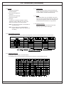
1.2.10
Backup Battery Calculation
• The following table is used to calculate the standby battery capacity required by NFPA when using the D7024:
1.2.11
Standby Current Load
• Battery AH - (20% Storage + 0.375 AH's Alarm)
• The following table is the derated battery divided by hours minus the control standby (175 mA):

Page 6 Copyright © 1997 Radionics, Inc. D7024 Reference Guide
2.0 Enclosure Installation
The D7024 control/communicator and the enclosure are
shipped together. The control, however, still needs to be
installed into the enclosre. Hardware for mounting the
enclosure to a wall, and the control to the enclosure is
located in the hardware pack.
2.1 Install the Enclosure
• Use the enclosure as a template and mark the top
mounting holes on the mounting surface.
• Pre-start the mounting screws for these two holes.
Slide the enclosure onto these mounting screws so
that the screws move up into the thinner section of
the holes. Tighten the screws.
• Screw in the remaining two screws in either set of
bottom mounting holes.
• Knock out the desired wire entrances on the enclo-
sure.
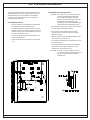
2.2 Install the Control/Communicator
CAUTION: The control is static sensitive. Make sure
you touch ground before handling the
control. This will discharge any static
electricity in your body. Example: Run the
ground wire to the enclosure before
handling the control. Then keep holding the
ground wire while installing the control.
• Insert the two support posts into the control retainer
holes as shown in the diagram below.
• Press the 1/8" nylon standoffs into the control
retainer holes as shown. This provides support
behind the control.
• Slide the top of the control into the retainer tabs (the
slots under the top of the frame).
• Once in the retainer tabs, the control will rest on the
two support posts.
• Secure the bottom of the control by screwing the 2
bottom corners through the support posts and
through to the control retainer holes.
CAUTION: Once the control is installed, be sure to
connect the supplied ground wire between
the door and the enclosure using the
supplied nuts.

D7024 Reference Guide Copyright © 1997 Radionics, Inc. Page 7
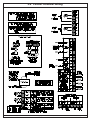
3.0 Control Terminal Wiring

Page 8 Copyright © 1997 Radionics, Inc. D7024 Reference Guide
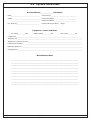
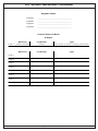
4.0 System Worksheet
Account Number_______________Information
Name_______________________________________ Contact Person___________________________________
Address_____________________________________ Voice Phone Number_______________________________
_____________________________________ Panel Phone Number_______________________________
City, State, Zip_______________________________ Panel Answers Phone After [ ] Rings
Equipment Location and Notes
AC Voltage__________VAC Battery Voltage__________VDC AUX Current__________mA
Control Panel__________________________________________________________________________________________
Telephone Jack________________________________________________________________________________________
Telephone On Same Line as Panel_________________________________________________________________________
Earth Ground Connection________________________________________________________________________________
Notification Appliances__________________________________________________________________________________
Initiating Devices______________________________________________________________________________________
Miscellaneous Notes
____________________________________________________________________________
____________________________________________________________________________
____________________________________________________________________________
____________________________________________________________________________
____________________________________________________________________________
____________________________________________________________________________
____________________________________________________________________________
____________________________________________________________________________
____________________________________________________________________________
____________________________________________________________________________

D7024 Reference Guide Copyright © 1997 Radionics, Inc. Page 9
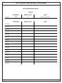
4.0 System Worksheet (continued)
Personal Identification Numbers
Example
PIN Number Authority Level Name
User 00
1001 3 Henry M. Jones
PIN Number Authority Level Name
User 00
User 01
User 02
User 03
User 04
User 05
User 06
User 07
User 08
User 09
User 10
User 11
User 12
User 13
User 14
User 15

Page 10 Copyright © 1997 Radionics, Inc. D7024 Reference Guide
4.0 System Worksheet (continued)
Keypad Location
Keypad #1 __________________________________________
Keypad #2 __________________________________________
Keypad #3 __________________________________________
Keypad #4 __________________________________________
Point Location and Notes
Example
Device(s) Location(s) Type
Point 1
Smoke Detector Hallway Fire, Alarm on Short, Latching, Verification
Device(s) Location(s) Type
Point 1
Point 2
Point 3
Point 4
Point 5
Point 6
Point 7
Point 8

D7024 Reference Guide Copyright © 1997 Radionics, Inc. Page 11
5.0 Operating Guide
5.1 Understanding the Built-in Keypad
The keypad built-in to the control/communicator is an alpha-numeric LCD keypad. It has a two line by 16 character display to
provide information on various control panel functions. In most instances, the top line of the display provides general system
status information, while the second line describes specific devices that may be relevant to the current system status. When
keys are being pressed, the display usually shows the current action on the top line, while displaying rotating menu choices
on the second line. A built-in sounder is used to annunciate keystroke entries and as an interior warning device.
5.2 Understanding the D7033 Keypad
The D7033 keypad is an alpha-numeric LCD keypad. Up to four of these keypads can be mounted apart from the main
control/communicator to provide additional locations for system status and control. The LCD display and keys operate
identically to those of the built-in keypad on the control panel.
The volume and backlight intensity of the D7033 keypad can be changed in the following manner:
• Volume Control - The keypad sounder volume can be adjusted using the [1] and [4] keys along with the [*] key.
- Hold the [*] key while pressing the [1] key to increase the volume or the [4] key to decrease the volume.
• Backlight Control - The display backlight intensity can be adjusted using the [3] and [6] keys along with the [*] key.
- Hold the [*] key while pressing the [3] key to increase the brightness or the [6] key to decrease the brightness.

Page 12 Copyright © 1997 Radionics, Inc. D7024 Reference Guide
5.0 Operating Guide (continued)
5.3 System Operation
5.3.1 Modes of System Operation
There are three modes of system operation for the D7024 control/communicator:
• Normal Operation: When the system is operating normally, it displays “SYSTEM NORMAL” on the top line of the
display, the Power LED is on steady, and no other LEDs are lit. If the system is programmed to
require a PIN, the second line of the LCD screen will display “ENTER PIN:”, otherwise the control
panel will bypass this display and will show a rotating menu of possible user actions.
• Alarm Operation: When an alarm occurs, the top line of the display will show “FIRE ALARM”. This display will override
any other system display. The second line of the display will show the number of the point that is in
alarm, alternating with the programmed description for the affected point. If more than one alarm (or
other off-normal condition) is active, they will be shown on the second line of the display, one after
another. The built-in sounder turns on with a steady tone, and outputs programmed to activate with
the current alarm condition(s) will activate.
• Trouble Operation: When a trouble condition occurs (e.g. wiring for a point is cut, AC power fails, etc.), the sounder will
activate briefly, every 10 seconds. The Trouble LED will light and the top line of the display will
show “SYSTEM TROUBLE”. The second line of the display will identify the specific problem.
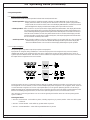
5.3.2
Point/Zone Mapping
The panel supports a system to map the input points to output points.
Input points are assigned, during installation, to a zone. Each input point can be assigned to only one zone; however,
multiple input points can be assigned to the same zone. Output points are also assigned; however, they can be as-
signed to up to four different zones. This allows an alarm condition on an input device assigned to zone one to cause all of
the output devices assigned to zone one to activate.
Assign input points to zones in [PROG/0] [4-PROG INPUTS] [3-ZONE ASSIGN]. Remember, each input point can only
be assigned to one zone; however, a zone can have multiple input points assigned to it. In our graphic, above, there are
7 smoke detectors assigned to each zone. Output points (NACs) are assigned in [PROG/0] [5-PROG OUTPUTS] [3-
ZONE ASSIGNS]. Here, individual output points can be assigned to up to four zones. This allows a smoke detector on the
first floor of a building (assigned to zone 1) to cause horns (also assigned to zone 1) to sound on floors 1 and 2.
Up to 64 zones can be assigned. Zones 1 to 50 can be assigned by the installer. Zones 51 to 63 are preassigned to
system conditions.
Preassigned Zones:
• Zone 63: General Alarm - active while any alarm, including supervisory, is present; remains active even while system
is silenced.
• Zone 62: General Trouble - active while any system trouble is present.
• Zone 61: General Waterflow - active while any waterflow alarm is present.

D7024 Reference Guide Copyright © 1997 Radionics, Inc. Page 13
5.0 Operating Guide (continued)
• Zone 60: No AC - active when AC power fails.
• Zone 59: Alarm Verification - active while alarm verification is in progress, starting with the first detection of an alarm to be
verified and clearing at the end of the five second power stabilization time.
• Zone 58: General Supervisory Alarm - active when any supervisory alarm condition is present.
• Zone 57: Communication Trouble - active when the dialer has failed to communicate, or all monitored phone lines are
indicating line fault; remains active until communication through the digital communicator has been
restored.
• Zone 56: Presignal or Alarm Investigation Delay Active - active during the time after a zone or point has been tripped,
but before the NACs are activated.
• Zone 55: Releasing Cycle Started - active after two detectors have been tripped to start a releasing cycle; clears
when the release occurs or is aborted.
• Zone 54: Activates for ground start.
• Zone 53: General Fire Alarm - active when a fire alarm condition is present; does not activate for waterflow.
• Zone 51 to 53 are reserved for future use.
5.4 Fire Silence/Reset
During a fire alarm, exit the premises immediately. Do not enter the premises unless accompanied by the appropriate
Emergency Services' personnel, or after they have given the OK to enter. When it has been determined that there is no
fire, you may silence the horns/bells to allow further investigation of the devices that initiated the alarm, or you may reset
the system to return it to normal operation.
Before the [Reset] key is used, determine which smoke detector has alarmed so the monitoring company may
verify its operation.
The [Silence] key turns off the horns/bells, but does not reset the alarm status and does not return the tripped input to
normal service. Detectors that were tripped will stay in alarm and can be checked (usually by means of an LED on the
device) to see which detector caused the alarm. Once the detectors causing the alarm have been identified, the system
should be reset to return it to normal service.
The [Reset] key clears the system alarm status, and briefly turns off power to the detectors to reset them. This command
is required after any fire alarm affecting a point programmed for latching operation (which is the normal configuration).
5.5 System Trouble
A system trouble will be indicated by a short beep from the panel or keypad sounders every 10 seconds. The LCD will
display “SYSTEM TROUBLE”, followed by a description of the trouble condition. The system can diagnose and display a
variety of trouble conditions, including those affecting the input points, NAC circuits, power, battery, system grounding, and
internal operations of the fire control panel. Notify your installing company immediately if the system trouble message is
displayed.
The system trouble beep can be silenced with the [Silence] key. After problems have been remedied, [Reset] should be
pressed to clear the “SYSTEM TROUBLE” display.
5.6 Fire Safety
WARNING: No fire detection device or system should be considered 100% foolproof.
This fire alarm system can provide early warning of a developing fire. Such a system, however, does not ensure protection
against property damage or loss of life resulting from a fire. Any fire alarm system may fail to warn for any number of
reasons (e.g. smoke not reaching a detector that is behind a closed door).
When considering detectors for residential applications, refer to NFPA Standard 72, “The National Fire Alarm Code.” This
standard is available at a nominal cost from: The National Fire Protection Association, Batterymarch Park, Quincy, MA 02269.

Page 14 Copyright © 1997 Radionics, Inc. D7024 Reference Guide
5.0 Operating Guide (continued)
5.6.1 If Installed in Family Residences
Adherence to NFPA Standard 72 can lead to reasonable fire safety when the following items are practiced:
• Minimize hazards: Avoid the three traditional fire killers: smoking in bed, leaving children home alone, and cleaning with
flammable liquids.
• Providing a fire warning system: Most fire deaths occur in the home, the majority, during sleeping hours. The minimum
level of protection requires smoke detectors to be installed outside of each separate sleeping area and on each additional
story of the dwelling.
For added early warning protection, it is recommended that detectors be installed in all separated areas including the
basement, bedrooms, dining room, utility room, furnace room, and hallways.
5.6.2 Having and Practicing an Escape Plan
A fire warning may be wasted unless the family has planned in advance for a rapid and safe exit from the building.
• Draw a floor plan of the entire house showing two exits from each bedroom and two from the house. Since stairwells
and hallways may be blocked during a fire, the plan should provide exits from bedroom windows. Make copies of the
plan and practice it with all family members.
• Pre-arrange a meeting place outside and away from the residence. Once out of the building, all occupants should
immediately go to the pre-selected location and be accounted for.
• Provide a barricade between family members and fire, smoke, and toxic gases (e.g. close all bedroom doors before
retiring).
• Children should be instructed on opening their bedroom windows and exiting safely from the building. If exiting is not
possible, they should be taught to stay at the open window and shout for help until it arrives.
• In the event of a fire alarm after retiring, wake the children by shouting to them from behind your closed door. Tell them
to keep their bedroom doors closed.
• If the top of your bedroom door is uncomfortably hot, do not open it. There is most likely fire, intolerable heat, or
smoke on the other side. Shout to all family members to keep their bedroom doors closed and to exit the building via
alternate routes.
• If the top of the door is not uncomfortably hot, brace the bottom of the door with your foot, and the top with one hand,
then open the door about one inch. Be prepared to slam the door shut if there is any pressure against the door or if
any hot air rushes in.
• If there is no evidence of excessive heat or pressure, leave the room and close the door behind you. Shout
appropriate instructions to all family members and immediately leave the building via the pre-planned routes. If heavy
smoke is present, drop to your hands and knees, or crawl to remain below the smoke level.
5.6.3
Installation Considerations
Proper location of detection devices is one of the most critical factors in a fire alarm system (see text below and the figure
at the top of the next page).
The following are some general considerations:
• Smoke detectors should not be installed in “dead air” spaces or close to ventilating or air conditioning outlets because
smoke may be circulated away from the detector. Locations near air inlets should be favored.
• Avoid areas subject to normal smoke concentrations such as kitchens, garages, or near fireplaces.
• Do not install smoke detectors where normal area temperatures are above 100 degrees F (38 degrees C) or below 32
degrees F (0 degrees C).
• Areas of high humidity and dust concentrations should be avoided.
• The edge of ceiling mounted detectors should be no closer than 4 inches (10 cm) from any wall.
• Place the top edge of wall mounted detectors between 4 and 12 inches (10 and 30 cm) from the ceiling.
For exact mounting information, refer to the instructions provided with the smoke detectors.

D7024 Reference Guide Copyright © 1997 Radionics, Inc. Page 15
5.0 Operating Guide (continued)
5.7 Personal Identification Numbers
The Personal Identification Number (PIN) is the 4 digit code users enter at the keypad to gain access to the system. A PIN
may be assigned to each User Number 00 - 15. The User Number identifies each person using the system. There are 16
possible User Numbers (00 - 15). The Authority Level assigned to each User Number determines which functions each
user will be able to perform.
Your system may have up to 16 different PINs, each 4 digits long. Each User Number can have only one PIN. Attempt-
ing to assign the same PIN to multiple User Numbers will result in the three-beep error tone, and the change will not be
made.
User Number 00 is designated as a Master Code. It can be used to silence alarms, reset, bypass, and program the unit.
User Number 00 is shipped from the factory with the sequence of 9876. This code should be changed to one of your
personal preference, and must be assigned maximum authority. PINs should never be programmed with common
sequences such as 1111, 1234, or 2468 because they are easily violated.
Authority Levels
Authority Levels are assigned to PINs to determine which
functions each user will be able to perform. Level 3 (minimum)
will allow alarm silence and view history options only. Level 2
(medium) adds the capability to reset the system, access test
modes, initiate fire drills, and disable input or output devices.
Level 1 (maximum) adds the capability of programming the
control panel. Level 0 (none) prevents all system access.
5.8 Error Displays
Control panel problems are indicated by one of the following messages on the top line of the display. Contact your installing
company if problems persist.
1. “FIRE ALARM” - One or more points is in alarm.
2. “SUP'VISORY ALARM” - A supervisory condition exists (e.g. a shut-off valve is closed).
3. “SYSTEM TROUBLE” - A trouble condition exists (e.g. wiring for a point is cut, AC power fails, etc.).
4. “POINT TROUBLE” - One of the points is not responding to the control panel. This may also be displayed during power-up
(if so, ignore).
5. “DISABLED DEVICE” - An input or output device has been disabled.
5.9 Testing
Any of seven special test modes can be selected using the Test key found on the built-in and D7033 keypads.
• Walk test: Checks the points to assure that detectors connected to a point will report an alarm to the control. While in
this mode, the LCD will show system test status and the trouble sounder will sound every 10 seconds.
• Communicator test: The communicator will send a test report. While communication is in progress, the Power LED will
flash. When the communication succeeds, a long keypad beep will be heard, the Power LED will return to normal, and the
display will return to normal.
NOTE: This test is available only if your system transmits alarms and system information to a monitoring service,
and has been programmed by the security installing company to permit communicator tests.
Level Allowed Operations
Maximum (1) all panel operations, including
programming
Medium (2) system test modes, fire drill, reset,
disable, silence, view history
Minimum (3) silence, view history
None (0) none

Page 16 Copyright © 1997 Radionics, Inc. D7024 Reference Guide
• Dial out for downloading: The control panel will dial out to the remote programmer. This test requires that phone
number 3 (computer) and account code 1 be programmed.
• Test battery/NAC circuits: If a power failure occurs, your control panel has a built-in battery that will continue to power
the system for several hours. The control panel automatically recharges the battery when
power is restored. In this test mode, the system will operate the alarm relay and test the battery
for 2 seconds. The test result will be displayed at the end of the test, and will not be reported to
the central station. Pressing the Clear key or the Command key will return the display to
standby mode, or the unit will time out after 20 seconds.
• Answer phone for downloading: Verifies the panel's ability to answer the phone line for remote programming. The
remote computer must give the proper agency and remote passwords for connection
to be maintained.
• Manually activate outputs: Allows a selected output to be turned on and turned off manually.
• Read zone input levels: Shows the status of a selected internal point. This status will be updated every five seconds.
In addition, this test mode can be used to display line voltage, battery voltage, ground fault
level, NAC current, and phone line level status.
5.10 Remote Program Dial-out and Answer
Call for Remote Programming
Phone numbers 1 and 3 must be programmed, along with account code 1. The panel will call phone number 3 and
attempt to connect for downloading. While programming is underway, the Trouble LED will flash. If the panel is already
using the phone line, it will sound the three beep error tone.
Answer for Remote Programming
The panel will immediately pick up the phone line to answer a remote programming call. While programming is under-
way, the Trouble LED will flash. In addition to allowing a connection for remote programming, this will allow on-site PC
downloading. If the panel is already using the phone line for a report communication, it will sound the three beep error
tone.
5.0 Operating Guide (continued)

D7024 Reference Guide Copyright © 1997 Radionics, Inc. Page 17
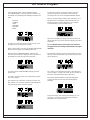
6.0 How to Program
The keypad will (under normal conditions) display
"SYSTEM NORMAL" on the top line and, "SELECT:" on
the bottom line, followed by the following scrolling menu
items:
• PROG/0
• CMND/#
• TEST
• HISTORY
• DISABLE
• DRILL
To select one of the menu items, simply press its corre-
sponding key on the keypad at any time.
When a menu item is selected, the Trouble LED will begin
to flash and the display's backlighting will turn on.
When PROG/0, CMND/#, DISABLE, and TEST are
selected, the menu item is displayed on the top line and
the bottom line scrolls through sub-menu items.
To return to the SYSTEM NORMAL display, press the
[Clear/*] key.
To select a sub-menu, press the corresponding number
key on the keypad.
The keypad may, at this time, prompt you to enter your
PIN number. If so, enter the number and the display will
automatically go to the sub-menu display.
To return to a previous screen at any time, press the
[Clear/*] key. Doing so deep within a sub-menu will
eventually return you to the SYSTEM NORMAL display.
When a sub-menu item prompts you to enter data, do so
followed by the [Cmnd/#] key. If data already exits at a
particular location, it will be displayed. You can either
accept that data or enter new data over it.
When the [Cmnd/#] key is pressed to enter the data, the
display will return you to the sub-menu display you were in
previously.
For a complete listing of each menu and sub-menu,
see pages 19-21. For a listing of the Defaults, see pages
24 and 25.
The HISTORY option is not menu driven; rather it is a list.
After you press the HISTORY key, the latest system event
will be displayed.
The "12/12" in our example means this is the 12th event
out of 12. DRILL: OVER is the event, 08:13 is the time of
the event, and 101196 is the date of the event.
The display will automatically scroll back through the
events until it reaches the end, then will display the
following:
At any time during your viewing of the history, you can
press the 7 or 9 keys to move forward or backward
through the list of system events.

Page 18 Copyright © 1997 Radionics, Inc. D7024 Reference Guide
6.0 How to Program (continued)
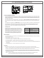
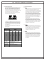
6.1 ALPHA Programming
When programming the Point Descriptions (4- PROG
INPUTS / 1- POINT NUMBER / 4- DESCRIPTION),
the numeric keys are used to enter alpha-numeric
information similar to the way telephone buttons are
used to process information over the phone lines: each
key representing 4 or more letters or symbols.
When you enter the Description programing section,
the display will show the following:
Characters are displayed on the second line as they
are entered. As each numeric key is pressed, it will
enter a different character each time it is pressed. For
example: repeatedly pressing the [2] key will enter A,
B, C, 2, A, B, etc.
The numeric keys and their values are shown in the
following table.
6.2 Format Programming
6.2.1
4/2
When 4/2 format is used, reports generated by points
consist of an event type (first digit) and a point
number (second digit). Digits may be programmed for
the following events: fire alarm, fire restoral, waterflow
alarm, supervisory alarm, point trouble, trouble
restore, point disable, disable restoral, and monitor
alarm. The same event type (first digit) will be sent for
any point. The point number is the second digit. Each
point may be programmed to a different digit. This
programming is done under 7- PROG FORMATS, 1-
4/2 POINT RPT.
Additionally, 18 system events may each be pro-
grammed with a unique two digit code. Events that
may be programmed this way include, for example:
system silence, fire drill, phone 1 trouble, and phone 2
restoral. This programming is done under 7- PROG
FORMATS, 2- 4/2 RPT CODS.
6.2.2
BFSK
Similar to the programming of system events for 4/2
formats, five system events may be programmed for
two unique digits each when the BFSK format is
used. This programming is done under 7- PROG
FORMATS, 3- BFSK RPT CODS.
6.2.3
SIA
The report that is sent by the SIA format when the
panel is silenced may be programmed. By default, the
panel will send "KB" when it is silenced. Any letters
may be programmed to be sent for this condition. To
program this, the number keys take the same letter
assignments as they have for programming point
descriptions.
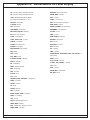
Numeric Key Values
1 Space 1 , ‘ & / # ! -
2 ABC2
3DEF3
4GHI4
5JKL5
6MNO6
7PRS7
8TUV8
9WXY9
0QZ0
#/CMD
enters the description and returns to
programming menu
*/CLEAR
returns to programming menu without
entering changes
SILENCE
moves cursor one space right
DISABLE
moves cursor one space left

D7024 Reference Guide Copyright © 1997 Radionics, Inc. Page 19
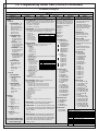
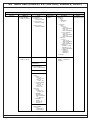
7.0 Programming Menu Tree (PROG/0)
For defaults, see page 24
SELECT:
PROG/0 CMND/# TEST HISTORY DISABLE DRILL
1- PROG TIME 2- SECURITY 3- PROG SYSTEM 4- PROG INPUTS
1- SYSTEM
MMDDYY
HHMM
2- AUTO TEST
1- TEST TIME
: Time of day
the automatic test occurs.
2- TEST FREQ
: Intervals the
automatic test reports are
sent. e.g. 7 days. The first
report will be sent when the
test time occurs, then every
7 days thereafter.
1- PINS
1- PROGRAMR
: Code used
by installer to configure and
operate the panel. Factory
default code is “9876” and
may be changed at any
time.
2- USERS
: Up to 15
additional user codes can
be programmed for the unit
to protect the system form
unauthorized operation and
allow a record to be kept of
actions by individual
system users.
2- AUTHORITY
: Determines
which system actions a user
can perform.
USER (01 - 15)
0- NONE
1- MAXIMUM
2- MEDIUM
3- MINIMUM
1- CITY BOX
: Reconfigures the
system to use notification
appliance circuit 2 as a signaling
circuit to drive a city box interface
for a municipal fire alarm reporting
system.
YES (1) NO (0)
2- TIMERS
1- SMOKE RESET
: Time the
smoke detector power is turned
off after reset. No alarms are
registered by the system for 5
seconds after power is tuned
back on.
(01 - 16 seconds)
2- AC FAIL DLY
: The # of hours
the control will wait after an AC
failure before sending and AC
Fail report. A setting of “1”
causes the system to send a
report when the battery reaches
25% of capacity.
1- WAIT FOR TIME
2- ENTER TIME
(00 - 24 Hours)
3- AUTO SILENCE
: Sets the time
for an autosilence NAC to
activate until it silences itself.
The same setting applies to all
NACs.
(00 - 99 Minutes)
4- (reserved)
5- DISPLAY RATE
: The speed
menus are shown on the LCD
screen, in units of 1/4 second.
(01 - 16 x .25)
3- (reserved)
4- OPTION BUS
1- UPDATE BUS
: Queries both
option buses and updates list of
connected devices.
2- SETUP KEYPAD
: Tells the
system how many keypads
should be supervised.
(0 - 4 Keypads)
5- PIN REQUIRED?
: A PIN can be
required before operations can be
performed.
1- LOCAL
YES (1) NO (0)
2- REMOTE
YES (1) NO (0)
6- REPORT/MONI
.: Communicator
and phone monitoring hardware
can be disabled or enabled.
YES (1) NO (0)
7- (reserved)
1- POINT NUMBER
(1 - 4/8) Note: Point 4 has different defaults than the
other points. See page 24.
0- ALARM/TROUBLE
1- ALARM
: When a point goes into an open circuit state,
the system alarms.
2- TROUBLE
: When point wiring is cut, AC power fails,
etc., the system responds with a trouble condition.
1- LATCHING
: If a zone is non-latching, the system
will reset alarm status automatically (but not reset
smoke power) when the input restores to the
standby condition. Other-wise, the system must be
manually reset.
YES (1) NO (0)
2- VERIFICATION
: Resets the detector once to see if
the alarm recurs before annunciating or sending a
signal.
YES (1) NO (0)
3- ZONE ASSIGN
: Each input can be assigned to
only one zone; however, multiple inputs can be
assigned to the same zone.
(00 - 63)
4- DESCRIPTION
: Each input (initiating circuit) can
be labeled with a 16 character description to identify
input.
5- (reserved)
6- LOOP RESPONSE
: Configure points to activate
with standard response time (setting 1) or one
system-wide programmed response time (setting 2).
1- FAST
: (500 ms)
2- PROGRAMMED
7- SILENCABLE
: Determines if a user can silence
the system or not. When an output device is
controlled by more than one point, if any non-
silenceable point is active, the output becomes non-
silenceable.
YES (1) NO (0)
8- LOCAL ONLY
: The input point gives local
annunciation only, with no communicator report.
YES (1) NO (0)
9- CONFIGURE
1- FIRE
: When activated, point displays “ALARM” on panel
and keypads, activates selected output devices, and
sends a fire alarm report (if programmed). Fire points
have “silenceable,” “latching,” and “output zone 0”
characteristics.
2- WATERFLOW
: When activated, point displays
“WATERFLOW ALARM” on panel and keypads,
activates selected output devices, and sends a waterflow
alarm report (if programmed). Waterflow points have
“non-silenceable,” “latching,” and “output point 0”
characteristics.
3- SUPERVISORY
: When activated, point displays
“SUPERVISORY ALARM” on panel and keypads, and
sends a supervisory alarm report (if programmed).
Supervisory points have “silenceable,” and “non-
latching,” characteristics with no output points.
4- MONITOR
: When activated, point displays “MONITOR
ALARM” on panel and keypads, activates selected
output devices, and sends a fire alarm report (if
programmed). If using the SIA format for communication
to the central station, a “UA” alarm will be sent instead of
a “FA” alarm. Monitor points have “silenceable” and
“latching” characteristics with no output zones.
5- RESET
: When activated, point initiates a panel reset
operation to clear alarms and reset smoke detectors.
6- SILENCE
: When activated, point initiates a panel silence
operation to turn off sounders.
7- (reserved)
8- (reserved)

Page 20 Copyright © 1997 Radionics, Inc. D7024 Reference Guide
SELECT:
PROG/0 CMND/# TEST HISTORY DISABLE DRILL
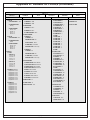
5- PROG OUTPUTS 6- PROG ACCOUNTS 7- PROG FORMATS 8- HISTORY DEFAULTS
1- NACS
1- NAC #1
1- AUTOSILENCE?
: The
NAC will silence itself
after a specified time
period. The system will
remain in alarm,
however, and must be
manually reset.
YES (1) NO (0)
2- CONFIGURATION
:
1- STEADY
: Output
programmed to turn
on steady for a fire
alarm.
2- PULSING
: Output
programmed to pulse
for a fire alarm in the
normal manner.
3- TEMPORAL
: Output
programmed to pulse
for a fire alarm in
Temporal 3.
4- CALIFORNIA
: Output
programmed to pulse
for a fire alarm in the
California Time
cadence.
3- ZONE ASSIGNS
Each output can be
assigned to up to 4
zones.
ZONE A, B, C, or D
(00=disabled)
(1-63)
2- NAC #2
1- AUTOSILENCE
2- CONFIGURATION
1- STEADY
2- PULSING
3- TEMPORAL
4- CALIFORNIA
3- ZONE ASSIGNS
Each output can be
assigned to up to 4
zones.
ZONE A, B, C, or D
(00=disabled)
(1-63)
2- RELAYS
1- LOCAL
1- RELAY #1
ZONE A, B, C, or D
(00 - 63)
2- RELAY #2
ZONE A, B, C, or D
(00 - 63)
2- REMOTE 1
(D7035)
1 - 8- RELAY #1 - #8
ZONE A, B, C, or D
(00 - 63)
3- REMOTE 2
SAME 1-8 OPTIONS AS
REMOTE 1
1- ACCOUNT NUMS
: The system can be programmed to
report different account codes to each of the two reporting
numbers. Account code 1 is used w/phone #1; account
code 2 is used w/phone #2.
1- NUMBER 1: New Number
2- NUMBER 2: New Number
2- PHONE NUMS
: The system can be programmed with 2
reporting phone #’s. Phone #1 is used w/line #1; phone #2
is used w/line #2. Downloading occurs on phone #3.
1- PHONE #1
Phone Number 1
2- PHONE #2
Phone Number 2
3- COMPTR PHONE:
Sets the number to
call for downloading.
3- PHON CONTROL
1- PHONE #1
: Selects which communication format to use or
disables communication for the phone number.
1- FORMAT
0- DISABLE
1- SIA, 110
2- CONTACT ID
3- BFSK
4- 4/2 TONE BST
5- 3/1 TONE BST
6- SIA, 300
2- MONITOR LINE
: Phone line monitor feature can be disabled
for each phone line.
YES (1) NO (0)
3- TONE FREQ
:
Determines data and
acknowledge frequency.
1- 19D, 14A, 10PS
2- 18D, 23A, 10PS
3- 19D, 14A, 20PS
4- 18D, 23A, 20PS
5- 19D, 14A, 40PS
6- 18D, 23A, 40PS
4- DIALING TYPE
: Determines what format the panel will dial
phone #’s 1,2, and 3.
1- PULSE ONLY
2- TONE ONLY
3- TONE PULSE
2- PHONE #2
SAME 1-5 OPTIONS AS PHONE #1
4- RPT STEERING
: Different classes of reports can be
directed to different phone numbers.
1- NONSUP ALRM
1- PHONE 1 ONLY: Report sent to phone #1 only.
2- PHONE 2 ONLY: Report sent to phone #2 only.
3- PHONE 1 AND 2: Report sent to ph #’s 1 and 2.
4- PHONE 2 BACKUP: Report sent to phone #1, then to phone
#2 if #1 fails.
5- NO REPORT: No report sent.
2- SUPVSRY ALRM
3- NONSUP RSTR
4- SUPVSRY RSTR
5- TROUBLE
6- TESTS
7- SILENCE
8- RESET
9- FIRE DRILL: Options 2 - 9 have the same choices as 1.
5- RING COUNT
: The number of phone rings before the
panel will seize the line to attempt downloading.
6- COMM. TRIES
: The system will always attempt 10 times
to communicate an event. The parameter determines after
which attempt the system will indicate a communication
failure condition.
(01 - 10)
7- MACH. BYPASS
: The downloading computer dials back
if an answering machine answers the phone before the
control. If the control detects the phone line ringing within
one minute of when the last ringing cycle stopped, then it
will answer on the first ring and seize the phone line.
YES (1) NO (0)
This section requires the used of
hex digits (0 through F). Because
the specific keys A through F are
not available on the keypad, the
following keys have been
substituted:
[History] = A
[Test] = B
[Disable] = C
[Drill] = D
[Silence] = E
[Reset] = F
1- 4/2 POINT RPT
0- FIRE ALRM D1
1- FIRE RSTR D1
2- WATERFLOW D1
3- SUPERVISE D1
4- TROUBLE D1
5- TRBL RSTR D1
6- DISABLE D1
7- DSBL RSTR D1
8- MONITOR D1
9- MORE
1- POINT 1 D2
2- POINT 2 D2
3- POINT 3 D2
4- POINT 4 D2
5- POINT 5 D2
6- POINT 6 D2
7- POINT 7 D2
8- POINT 8 D2
9- MORE
2- 4/2 RPT CODS
0- SYSTM IN TST
1- SYS TEST RST
2- SILENCE
3- FIRE DRILL
4- FIRE DRL RST
5- OPEN RST RPT
6- LOW BATTERY
7- LOW BATT RST
8- AC FAILURE
9- MORE
0- AC FAIL RST
1- TEST REPORT
2- OFF NORM TST
3- PHONE 1 TRBL
4- PN 1 TRB RST
5- PNONE 2 TRBL
6- PN 2 TRB RST
7- SYSTEM TROUB
8- SYS TRB RST
3- BFSK RPT CDS
1- OFF NRM TST
2- OPEN/RESET
3- SILENCE
4- FIRE DRILL
5- FIR DRIL RSTR
4- SIA SIL RPT
1- LEFT BYTE
2- RIGHT BYTE
1- CLEAR HSTRY
The history buffer holds the
latest 99 events. It
automatically deletes the
oldest items when it fills to 99.
If you want to manually clear
the history buffer, use this
menu item.
2- DEFAULT EE
This menu item sets the
EEPROM memory to the
factory default values.
3- ALT 4/2 CDES
This menu item defaults the
4/2 reporting codes to an
alternate industry-standard set
of reports.
The alternate default is as
follows (see page 25 for the
standard defaults):
4/2 POINT RPT
0- FIRE ALRM:
0
1- FIRE RSTR:
2
2- WATERFLOW:
0
3- SUPERVISE:
0
4- TROUBLE:
6
5- TRBL RSTR:
7
6- DISABLE:
5
7- DSBL RSTR:
2
8- MONITOR:
0
9- MORE
1- POINT 1:
1
2- POINT 2:
2
3- POINT 3:
3
4- POINT 4:
4
5- POINT 5:
5
6- POINT 6:
6
7- POINT 7:
7
8- POINT 8:
8
9- MORE
4/2 RPT CODS
0- SYSTM IN TST:
33
1- SYS TEST RST:
37
2- SILENCE:
9F
3- FIRE DRILL:
33
4- FIRE DRL RST:
37
5- OPEN RST RPT:
9F
6- LOW BATTERY:
69
7- LOW BATT RST:
79
8- AC FAILURE:
60
9- MORE
0- AC FAIL RST:
70
1- TEST REPORT:
30
2- OFF NORM TST:
33
3- PHONE 1 TRBL:
31
4- PN 1 TRB RST:
35
5- PNONE 2 TRBL:
32
6- PN 2 TRB RST:
36
7- SYSTEM TROUB:
33
8- SYS TRB RST:
37
7.0 Programming Menu Tree (PROG/0 continued)
For defaults, see page 25
19D 1900 Hz data tone
18D 1800 Hz data tone
14A 1400 Hz acknowledge tone
23A 2300 Hz acknowledge tone
10PS 10 pulses per second
20PS 20 pulses per second
40PS 40 pulses per second
For pre-assigned zones,
see chart in lower right
corner of this page.
Pre-assigned Zones
Zone 63 General Alarm
Zone 62 General Trouble
Zone 61 General Waterflow
Zone 60 No AC
Zone 59 Alarm Verification
Zone 58 General Supervisory Alarm
Zone 57 Communication Trouble
Zone 56 Pre-signal or Alarm Investigation Delay Active
Zone 55 Releasing Cycle Started
Zone 54 Activates for Ground Start
Zone 53 General Fire
These special digits can be entered by
pressing [Test] followed by a number key.
Press See Action
[Test] [1] * Touch Tone
2
“*” digit
[Test] [2] # Touch Tone
2
“#” digit
[Test] [3] / 3 second delay
[Test] [4] > Wait for dial tone
Page is loading ...
Page is loading ...
Page is loading ...
Page is loading ...
Page is loading ...
Page is loading ...
Page is loading ...
Page is loading ...
-
 1
1
-
 2
2
-
 3
3
-
 4
4
-
 5
5
-
 6
6
-
 7
7
-
 8
8
-
 9
9
-
 10
10
-
 11
11
-
 12
12
-
 13
13
-
 14
14
-
 15
15
-
 16
16
-
 17
17
-
 18
18
-
 19
19
-
 20
20
-
 21
21
-
 22
22
-
 23
23
-
 24
24
-
 25
25
-
 26
26
-
 27
27
-
 28
28


Ask a question and I''ll find the answer in the document
Finding information in a document is now easier with AI
Other documents
-
Radionics D7024 Operating instructions
-
Bosch D7024 User manual
-
-
 SILENT KNIGHT SK-2-E Fire Alarm Control Panel User manual
-
Mircom LT-1040 FX-350 Programming Manual
-
-
Niko 10-870 User manual
-
 Digital Monitoring Products PowerCom Fire Installation & Programming Guides
-
 Digital Monitoring Products XF6 Series User guide
-


