Page is loading ...

1511162-12MA
MATACTT1 TIG TORCH
OWNER’S MANUAL
12/2015
WARNING:
Read carefully and understand all ASSEMBLY AND OPERATION
INSTRUCTIONS before operating. Failure to follow the safety rules and other
basic safety precautions may result in serious personal injury.

Page of 11
1511162-12MA
2
MATCO TOOLS
EFFECTIVE DECEMBER 1, 2015
LIMITED WARRANTY
This warranty applies to the original purchaser and is subject to the terms and conditions listed below. This Limited Warranty is for
new equipment sold after the above date, providing coverage for defects in material and workmanship at the time it is shipped from
the factory.
Limited to the warranty periods below, Matco Tools will repair or replace the item under warranty that fails due to defects in material
and workmanship. Matco Tools must be notified within 30 days of the failure, so as to provide instructions on how to proceed with
the repair of your welder and warranty claim processing. Warranty period begins at the time the welder is purchased from an
Authorized Matco Tools distributor. Keep your receipt as proof of purchase.
Warranty Periods
Limited Warranty is divided into three categories. No Warranty, 1 year and 3 year.
No Warranty
Normal wear items, MIG gun parts (contact tips, nozzle, contact tip adapter, MIG gun liner), drive roll, electrode holder, ground
clamps, plasma torch parts (nozzle, electrode, diffuser, cover), and TIG torches are considered consumable items and are not
covered under warranty.
1 Year Accessories Warranty
Parts and Labor on MIG gun parts (except those listed under normal wear items), cables, regulator, and plasma torch (except those
listed under normal wear items) are covered for 1 year. Any shipping related to warranty repair is the responsibility of the
customer.
1 Year/3 Year Welder Warranty
Please see your product information to determine if your product has a 1 year or 3 year warranty. This warranty covers Parts and
Labor on items such as: transformer, reactor, rectifier, solenoid valve, PC board, switches, controls, gas valve, drive motor, drive
system other than drive roll and any other component that requires the removal of the sheet metal to access. Any shipping related
to warranty repair is the responsibility of the customer.
Voiding Warranty
Warranty does not apply to: shipping damage, misuse and abuse of the unit and alteration of the unit in any way.
Warranty Claim
This is a Parts and Labor warranty. Contact the Matco Tools distributor you purchased the unit from. Retain your receipt in the
case a warranty claim is needed. No warranty will be provided without the original receipt from an authorized Matco Tools
distributor. To make a warranty claim, contact your Matco Tools distributor. That Matco Tools distributor will contact the customer
service department for warranty instructions.

Page of 11
1511162-12MA
3
GENERAL SAFETY RULES
WARNING: Read and understand all instructions. Failure to follow all instructions listed
below may result in serious injury or death.
CAUTION: Do not allow persons to operate or assemble this unit until they have read
this manual and have developed a thorough understanding of how this unit works.
WARNING: The warnings, cautions, and instructions discussed in this instruction
manual cannot cover all possible conditions or situations that could occur. It must be
understood by the operator that common sense and caution are factors which cannot be built into
this product, but must be supplied by the operator.
SAVE THESE INSTRUCTIONS
IMPORTANT SAFETY CONSIDERATIONS
1.1 Your Welding Environment
-Keep the environment you will be welding in free from flammable materials.
-Always keep a fire extinguisher accessible to your welding environment.
-Always have a qualified person install and operate this equipment.
-Make sure the area is clean, dry and ventilated. Do not operate the welder in humid, wet or poorly
ventilated areas.
-Always have your welder maintained by a qualified technician in accordance with local, state and
national codes.
-Always be aware of your work environment. Be sure to keep other people, especially children,
away from you while welding.
-Keep harmful arc rays shielded from the view of others.
-Mount the welder on a secure bench or cart that will keep the welder secure and prevent it from
tipping over or falling.
1.2 Your Welder’s Condition
-Check ground cable, power cord and welding cable to be sure the insulation is not damaged.
Always replace or repair damaged components before using the welder.
-Check all components to ensure they are clean and in good operating condition before use.
1.3 Use of Your Welder
Do not operate the welder if the output cable, electrode, torch, wire or wire feed system is wet. Do
not immerse them in water. These components and the welder must be completely dry before
attempting to use them.
-Follow the instructions in this manual.

Page of 11
1511162-12MA
4
-Keep welder in the off position when not in use.
-Connect ground lead as close to the area being welded as possible to ensure a good ground.
-Do not allow any body part to come in contact with the welding wire if you are in contact with the
material being welded, ground or electrode from another welder.
-Do not weld if you are in an awkward position. Always have a secure stance while welding to
prevent accidents. Wear a safety harness if working above ground.
-Do not drape cables over or around your body.
-Wear a full coverage helmet with appropriate shade (see ANSI Z87.1 safety standard) and safety
glasses while welding.
-Wear proper gloves and protective clothing to prevent your skin from being exposed to hot metals,
UV and IR rays.
-Do not overuse or overheat your welder. Allow proper cooling time between duty cycles.
-Keep hands and fingers away from moving parts and stay away from the drive rolls.
-Do not point torch at any body part of yourself or anyone else.
-Always use this welder in the rated duty cycle to prevent excessive heat and failure.
1.4 Specific Areas of Danger, Caution or Warning
Electrical Shock
Electric arc welders can produce a shock that can cause injury or death. Touching
electrically live parts can cause fatal shocks and severe burns. While welding, all metal
components connected to the wire are electrically live. Poor ground connections are a hazard, so
secure the ground lead before welding.
-Wear dry protective apparel: coat, shirt, gloves and insulated footwear.
-Insulate yourself from the work piece. Avoid contacting the work piece or ground.
- Do not attempt to repair or maintain the welder while the power is on.
-Inspect all cables and cords for any exposed wire and replace immediately if found.
-Use only recommended replacement cables and cords.
-Always attach ground clamp to the work piece or work table as close to the weld area as possible.
-Do not touch the torch and the ground or grounded work piece at the same time.
-Do not use a welder to thaw frozen pipes.
Fumes and Gases
-Fumes emitted from the welding process displace clean air and can result in injury or
death.
-Do not breathe in fumes emitted by the welding process. Make sure your breathing air is clean and
safe.
-Work only in a well-ventilated area or use a ventilation device to remove welding fumes from the
environment where you will be working.
-Do not weld on coated materials (galvanized, cadmium plated or containing zinc, mercury or
barium). They will emit harmful fumes that are dangerous to breathe. If necessary use a ventilator,
respirator with air supply or remove the coating from the material in the weld area.
-The fumes emitted from some metals when heated are extremely toxic. Refer to the material safety
data sheet for the manufacturer’s instructions.
-Do not weld near materials that will emit toxic fumes when heated. Vapors from cleaners, sprays
and degreasers can be highly toxic when heated.

Page of 11
1511162-12MA
5
UV and IR Arc Rays
The welding arc produces ultraviolet (UV) and infrared (IR) rays that can cause injury to
your eyes and skin. Do not look at the welding arc without proper eye protection.
-Always use a helmet that covers your full face from the neck to top of head and to the back of each
ear.
-Use a lens that meets ANSI standards and safety glasses. For welders under 160 amp output, use
a shade 10 lens; for above 160 amp, use a shade 12. Refer to the ANSI standard Z87.1 for more
information.
-Cover all bare skin areas exposed to the arc with protective clothing and shoes. Flame-retardant
cloth or leather shirts, coats, pants or coveralls are available for protection.
-Use screens or other barriers to protect other people from the arc rays emitted from your welding.
-Warn people in your welding area when you are going to strike an arc so they can protect
themselves.
Fire Hazards
Do not weld on containers or pipes that contain or have had flammable, gaseous or liquid
combustibles in them. Welding creates sparks and heat that can ignite flammable and
explosive materials.
-Do not operate any electric arc in areas where flammable or explosive materials are present.
-Remove all flammable materials within 35 feet of the welding arc. If removal is not possible, tightly
cover them with fireproof covers.
-Take precautions to ensure that flying sparks do not cause fires or explosions in hidden areas,
cracks or areas you cannot see.
-Keep a fire extinguisher close in the case of fire.
-Wear garments that are oil-free with no pockets or cuffs that will collect sparks.
-Do not have on your person any items that are combustible, such as lighters or matches.
-Keep work lead connected as close to the weld area as possible to prevent any unknown,
unintended paths of electrical current from causing electrical shock and fire hazards.
Hot Materials
Welded materials are hot and can cause severe burns if handled improperly.
-Do not touch welded materials with bare hands.
-Do not touch the torch after welding until it has had time to cool down.
Sparks/Flying Debris
Welding creates hot sparks that can cause injury. Chipping slag off welds creates flying
debris.
-Wear protective apparel at all times: ANSI-approved safety glasses or shield, welder’s hat and ear
plugs to keep sparks out of ears and hair.

Page of 11
1511162-12MA
6
Electromagnetic Field
-Electromagnetic fields can interfere with various electrical and electronic devices such as
pacemakers.
-Consult your doctor before using any electric arc welder or cutting device.
-Keep people with pacemakers away from your welding area when welding.
-Do not wrap cable around your body while welding.
-Wrap the torch and ground cable together whenever possible.
-Keep the torch and ground cables on the same side of your body.
Shielding Gas Cylinders Can Explode
High pressure cylinders can explode if damaged, so treat them carefully.
-Never expose cylinders to high heat, sparks, open flames, mechanical shocks or arcs.
-Do not touch cylinder with the torch.
-Do not weld on the cylinder
-Always secure cylinder upright to a cart or stationary object.
-Keep cylinders away from welding or electrical circuits.
-Use the proper regulators, gas hose and fittings for the specific application.
-Do not look into the valve when opening it.
-Use protective cylinder cap whenever possible.
1.5 Proper Care, Maintenance and Repair
-Always have power disconnected when working on internal components.
- Do not touch or handle PC board without being properly grounded with a wrist strap. Put PC board
in static proof bag to move or ship.
-Do not put hands or fingers near moving parts such as drive rolls of fan.
USE AND CARE
Do not modify this unit in any way. Unauthorized modification may impair the function and/or
safety and could affect the life of the equipment. There are specific applications for which this
unit was designed.
Always check for damaged or worn out parts before using this unit. Broken parts will affect
the operation. Replace or repair damaged or worn parts immediately.
Store idle. When this unit is not in use, store it in a secure place out of the reach of children.
Inspect it for good working condition prior to storage and before re-use.
TECHNICAL SPECIFICATIONS
Item
Description
Max Amperage
150 amp
Cooling Method
Air-Cooled
Duty Cycle
35% @ 150 amp
Suggested Tungsten
.020 to 1/16"
Torch Cable Length
10 ft.
Torch Style
17V
Weight
3 lbs.

Page of 11
1511162-12MA
7
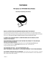
KNOW YOUR TORCH
Description
This Air Cooled TIG torch is designed to operate with the MP140 AND MP240 welders for DC lift
start TIG welding on steels or stainless steels. This torch may also be used on other TIG welding
units with Dinse 10-25 twist lock style weld terminals.
The Air Cooled TIG torch is rated at 150A at 35% duty cycle. This torch is ideal for light fabrication,
welding repair and maintenance operations.
Torch Cable
The 10 ft. long torch cable delivers the welding current and shielding gas to the arc.
Gas Flow Valve
This torch gas connection goes directly to the inert regulator/flowgauge connected to your bottle of
shielding gas. This valve controls the flow of shielding gas for welding.
Nozzle
Three nozzles are supplied with this TIG torch. These nozzles direct the flow of the shielding gas
from the TIG torch to the arc
Collet
Three collets are supplied with the TIG Torch. They are sized to the size of the tungsten you will be
using. They hold the tungsten into the TIG Torch.
Inert Gas Connection
This connection is used to connect your source of shielding gas to the TIG torch. Connect this
connection to your shielding gas regulator.
Torch
Cable
Gas Flow
Valve
Nozzle
Collet
Inert Gas
Connection

Page of 11
1511162-12MA
8
INSTALLATION
EXPOSURE TO A WELDING ARC IS EXTREMELY HARMFUL TO THE EYES AND SKIN!
Prolonged exposure to the welding arc can cause blindness and burns. Never strike an arc
or begin welding until you are adequately protected. Wear flame-proof welding gloves, a
heavy long sleeved shirt, trousers without cuffs, high topped shoes, and an ANSI approved
welding helmet.
1. INSTALLATION OF TIG TORCH
1.1 Remove the ground cable and the electrode holder from the weld output connections. Install the
ground cable to the Positive (+) weld output connection.
1.2 Secure the ground clamp to the work piece
1.3 Connect a regulator to a bottle of ARGON gas. Then connect the gas connection from the TIG
torch to the regulator.
1.4 Connect the TIG torch weld cable to the Negative (-) weld output connection.
1.5 Set desired amperage on the amperage control knob on the front panel of the welder.
1.6 Turn on the input power switch on the welder.
Be aware that the TIG torch will be electrically HOT when the Input Power Switch on the welder is
turned on.
1.7 Turn on the regulator on the bottle of shielding gas and adjust the regulator to approximately 20
CFH. Then open the shielding gas valve on the torch to start the flow of shielding gas.
1.8 Touch the tungsten that is installed in the TIG torch, to the work piece and quickly pull away
approximately 1/4" to create an arc.
DC TIG OPERATION
EXPOSURE TO A WELDING ARC IS EXTREMELY HARMFUL TO THE EYES AND SKIN!
Prolonged exposure to the welding arc can cause blindness and burns. Never strike an arc
or begin welding until you are adequately protected. Wear flame-proof welding gloves, a
heavy long sleeved shirt, trousers without cuffs, high topped shoes, and an ANSI approved
welding helmet.
Be aware that the TIG torch will be electrically HOT when the Input Power Switch on the welder is
turned on.
1. Remove the ground cable and the electrode holder from the weld output connections. Install the
ground cable to the Positive (+) weld output connection.
2. Secure the ground clamp to the work piece
3. Connect a regulator to a bottle of ARGON gas. Then connect the gas connection from the TIG
torch to the regulator.

Page of 11
1511162-12MA
9
4. Connect the TIG torch weld cable to the Negative (-) weld output connection.
5. Set desired amperage on the amperage control knob on the front panel of the welder.
6. Turn on the input power switch on the welder.
7. Turn on the regulator on the bottle of shielding gas and adjust the regulator to approximately 20
CFH. Then open the shielding gas valve on the torch to start the flow of shielding gas.
8. Follow these steps for striking an arc while TIG welding.
8.1 Open the shielding gas valve on the torch handle to begin gas flow.
8.2 Rest the TIG torch nozzle on the work piece taking care to not touch the installed tungsten
electrode.
8.3 Twist the torch to make contact between the work piece and the tungsten.
8.4 Lift torch away from the work piece about 1/8 inch.
8.4 Move down the joint to be welded by pushing the torch.
8.5 Insert filler metal in the leading edge of the weld puddle as needed.
MAINTENANCE
• Maintain your MATCO TIG TORCH. It is recommended that the general condition of MATCO
TIG TORCH be examined before it is used. Keep MATCO TIG TORCH in good repair by
adopting a program of conscientious repair and maintenance. Have necessary repairs made by
qualified service personnel.
• Periodically clean dust, dirt, grease, etc. from your torch.
• Replace power cord, ground cable, ground clamp, or electrode assembly when damaged or
worn.

Page of 11
1511162-12MA
10
DIAGRAM & PARTS LIST
Reference #
Part#
Description
Qty.
1
105500001
DINSE CONNECTOR 10-25
1
2
105500002
GAS CONNECTOR CAP
1
3
105500003
GAS CONNECTOR
1
4
105500004
TORCH BODY
1
5-1
105500005
LONG BACK CAP
1
5-2
105500006
SHORT BACK CAP
1
6
105500007
TORCH STOCK
1
7
105500008
COLLET CAP
1
8-1
105500009
COLLET 1.0
1
8-2
105500010
COLLET 1.6
1
8-3
105500011
COLLET 2.0
1
9-1
105500012
NOZZLE #4
1
9-2
105500013
NOZZLE #5
1
9-3
105500014
NOZZLE #6
1
165500001
OWNER’S MANUAL
1
For technical questions contact our welder help line at 1-888-762-4045

Page of 11
1511162-12MA
11
Distributed by
MATCO TOOLS
4403 ALLEN ROAD
STOW OH 44224
www.matcotools.com
Made in China
/