Garmin VHF 315 Marine Radio Installation guide

Category
Telephone handsets
Type
Installation guide

This manual is also suitable for

VHF 315 SERIES
INSTALLATION
INSTRUCTIONS
Important Safety Information
WARNING
See the Important Safety and Product Information guide in the
product box for product warnings and other important
information.
CAUTION
Always wear safety goggles, ear protection, and a dust mask
when drilling, cutting, or sanding.
NOTICE
When drilling or cutting, always check what is on the opposite
side of the surface.
Registering Your Device
Help us better support you by completing our online registration
today. Keep the original sales receipt, or a photocopy, in a safe
place.
1
Go to my.garmin.com.
2
Sign in to your Garmin
®
account.
Tools Needed
Pencil
Drill
22 mm (
7
/
8
in.) drill bit or hole saw
3 mm (
1
/
8
in.) drill bit
13 mm (
1
/
2
in.) drill bit
4.76 mm (
3
/
16
in.) wrench (for mounting the handset
connector)
Additional drill bits appropriate for the surface and hardware
Phillips screwdriver
Rotary cutting tool or jigsaw (for mounting the active speaker)
Marine sealant (optional)
Mounting Considerations
NOTICE
This device should be mounted in a location that is not exposed
to extreme temperatures or conditions. The temperature range
for this device is listed in the product specifications. Extended
exposure to temperatures exceeding the specified temperature
range, in storage or operating conditions, may cause device
failure. Extreme-temperature-induced damage and related
consequences are not covered by the warranty.
You must mount the device in a location where it will not be
submerged.
You must mount the device in a location with adequate
ventilation where it will not be exposed to extreme
temperatures.
If possible, you should mount the device horizontally, with the
top of the device facing upward.
If you must mount the device vertically, you should orient it so
the connectors do not point upward. This helps avoid
potential water retention around the connectors.
Antenna Mounting and EME Exposure
WARNING
Radio operators with cardiac pacemakers, life-support
machines, or electrical medical equipment should not be
exposed to excessive radio-frequency (RF) fields, because the
RF field may interfere with the function of their medical
equipment.
CAUTION
This device generates and radiates radio frequency (RF)
electromagnetic energy (EME). Failure to observe these
guidelines may expose people to RF radiation absorption
exceeding the maximum permissible exposure (MPE).
Garmin declares a MPE radius of 2.48 m (97.64 in.) for this
system, which was determined using 25 W output to an omni-
directional, 6 dBi gain antenna. The antenna should be installed
to maintain a distance of 2.48 m (97.64 in.) between the antenna
and all people.
Mounting the Device
NOTICE
If you are mounting the device in fiberglass, when drilling the
pilot holes, it is recommended to use a countersink bit to drill a
clearance counterbore through only the top gel-coat layer. This
will help to avoid cracking in the gel-coat layer when the screws
are tightened.
Before you mount the device, you must select a mounting
location and determine the mounting hardware needed for the
surface.
NOTE: Mounting hardware is included with the device, but it
may not be suitable for the mounting surface.
1
Place the device in the mounting location and mark the
location of the pilot holes.
2
Using a bit appropriate for the surface and the mounting
hardware, drill a pilot hole for one corner of the device.
3
Loosely fasten the device to the surface with one corner and
examine the other three pilot-hole marks.
4
Mark new pilot-hole locations if necessary.
5
Remove the device from the mounting surface.
6
Drill the appropriate pilot holes for the other three marks.
7
Secure the device to the mounting location.
Active Speaker Mounting Considerations
NOTICE
This device should be mounted in a location that is not exposed
to extreme temperatures or conditions. The temperature range
for this device is listed in the product specifications. Extended
exposure to temperatures exceeding the specified temperature
range, in storage or operating conditions, may cause device
failure. Extreme-temperature-induced damage and related
consequences are not covered by the warranty.
The included active speaker is optional, and is not required
when installing the VHF 315 device. When selecting a mounting
location for the active speaker, observe these considerations.
To avoid interference with a magnetic compass, do not install
the active speaker closer than 50 cm (19.6 in.) to a compass.
You must install the active speaker inline with a GHS
11
handset.
You must install the active speaker within 1.2 m (48 in.) of the
location you want to connect the GHS 11 handset.
You must install the active speaker connected to the primary
handset (connected to the GHS 11 STATION 1 port) in the
wheelhouse or an adjacent room, in accordance with FCC
law.
May 2018
190-02416-02_0A
You can use the included 10 m (32 ft.) extension cable to
connect the active speaker to the VHF radio. You must select
a mounting location for the speaker where you can connect
the extension cable to the active speaker and to the GHS 11
STATION 1 port on the VHF radio. If needed, additional
extension cables are available from your Garmin dealer.
Mounting the Active Speaker
NOTICE
Be careful when cutting the hole to mount the speaker. There is
only a small amount of clearance between the case and the
mounting holes, and cutting the hole too large could
compromise the stability of the speaker after it is mounted.
Before you can mount the speaker, you must select a mounting
location.
1
Trim the template and make sure it fits at the mounting
location.
2
Secure the template to the mounting surface.
3
Using a 13 mm (
1
/
2
in.) drill bit, drill a hole inside the corner of
the line on the template to prepare the mounting surface for
cutting.
4
Using a rotary-cutting tool or jigsaw, cut the mounting surface
along the inside of the dashed line on the template.
5
Place the speaker in the cutout to test the fit.
6
If necessary, use a file and sandpaper to refine the size of
the cutout.
7
After the speaker fits correctly in the cutout, ensure the
mounting holes on the speaker line up with the pilot holes on
the template.
8
If the mounting holes on the speaker do not line up, mark the
new pilot-hole locations.
9
Using a 3 mm (
1
/
8
in.) drill bit, drill the pilot holes.
10
Remove the template from the mounting surface.
11
Install the included mounting gasket
À
on the back of the
speaker.
12
Make the necessary wiring connections (Connecting the
Active Speaker to the VHF Radio and Handset, page 3).
13
Place the speaker in the cutout.
14
Secure the speaker to the mounting surface using the
included M4 screws
Á
.
15
Snap the screw cover
Â
in place.
Installing the Handset Connector in the Mounting Surface
Before drilling a hole to mount the handset connector from the
active speaker, you should mount the active speaker and verify
that the cable from the active speaker is long enough to reach
the handset-connector mounting location (Mounting the Active
Speaker, page 2).
If you do not install the active speaker, you must verify that the
included extension cable is long enough to connect to the GHS
11 STATION 1 port on the VHF radio and to the handset-
connector mounting location.
You can use the included hardware to mount the handset
connector from the active speaker on the dashboard or other
mounting surface. If you do not install the active speaker, you
can use the hardware to mount the handset connector from the
included extension cable on the dashboard or other mounting
surface.
1
Using the mounting plate
À
as a template, trace the cable
hole in the center of the mounting plate and mark the screw
locations.
2
Set the mounting plate aside.
Do not drill through the mounting plate.
3
Using a 22 mm (
7
/
8
in.) drill bit or hole saw, drill the center
cable hole
Á
in the mounting surface.
4
Using a 3 mm (
1
/
8
in.) drill bit, drill the pilot holes.
5
Apply marine sealant between the mounting plate and the
mounting surface to help seal the holes (optional).
6
Using the included screws, attach the mounting plate to the
mounting surface.
7
Select an option:
If you installed the active speaker, route the long cable
from the active speaker to the connector mounting
location.
If you did not install the active speaker, connect the
female end of the included extension cable to the GHS 11
STATION 1 port on the VHF radio, and route the male end
of the extension cable to the connector mounting location.
8
Feed the connector
Â
through the back of the mounting
surface.
9
Apply marine sealant around the connector in the mounting
plate to help seal the hole (optional).
10
Secure the connector to the mounting plate using the
weather cap
Ã
and the nut
Ä
.
GHS 11 Mounting Considerations
NOTICE
This device should be mounted in a location that is not exposed
to extreme temperatures or conditions. The temperature range
for this device is listed in the product specifications. Extended
exposure to temperatures exceeding the specified temperature
range, in storage or operating conditions, may cause device
failure. Extreme-temperature-induced damage and related
consequences are not covered by the warranty.
You must install the primary handset (connected to the GHS
11 STATION 1 port) in the wheelhouse or an adjacent room,
in accordance with FCC law.
To avoid interference with a magnetic compass, do not install
the handset closer than 60 cm (23.6 in.) to a compass.
If you do not install the active speaker, you can use the
included 10 m (32 ft.) extension cable to connect the handset
to the VHF radio. You must select a mounting location for the
handset where you can connect the extension cable to the
handset and to the GHS 11 STATION 1 port on the VHF
radio. If needed, additional extension cables are available
from your Garmin dealer.
You can use the included screws to mount the handset
connector and the handset cradle mount on your boat. If the
2
included screws are not appropriate for the mounting surface,
you must purchase suitable hardware.
Installing the Handset Cradle
You should install the handset connector in the mounting
surface before installing the handset cradle (Installing the
Handset Connector in the Mounting Surface, page 2).
1
Select a mounting location for the handset cradle near the
handset connector.
TIP: To help determine the best location, you can place the
handset in the cradle, connect the handset to the connector,
and hold it against the mounting surface.
2
Using the cradle as a template, mark the screw locations.
3
Set the cradle aside.
Do not drill through the cradle.
4
Using a 3 mm (
1
/
8
in.) drill bit, drill the pilot holes.
5
Using the included M3.5 screws, secure the cradle to the
mounting surface.
Connection Considerations
You must connect the VHF 315 radio to power, to a GHS 11
handset, a VHF antenna, and a GPS source. When making
connections to the device, observe the following considerations.
You must connect the primary handset (installed in the
wheelhouse or adjacent room, in accordance with FCC law)
to the GHS 11 STATION 1 port.
You can connect up to three handsets to the radio. You can
purchase additional handsets from your Garmin dealer.
You can install the included active speaker (optional) in-line
with any handset connected to the radio. You can purchase
additional active speakers from your Garmin dealer.
You can connect the radio to a GPS source through the
NMEA 2000
®
network or through an external GPS antenna
(not included).
Connecting the Wiring Harness to Power
1
Route the wiring harness to the power source and to the
device.
2
Connect the red wire to the positive (+) battery terminal, and
connect the black wire to the negative (-) battery terminal.
Additional Grounding Considerations
This device should not need any additional chassis grounding in
most installation situations. If interference is experienced, the
grounding screw on the housing can be used to connect the
device to the water ground of the boat to help avoid the
interference.
Connecting a VHF Antenna
1
Mount the VHF antenna (sold separately) according to the
installation instructions provided with the antenna.
2
Connect the VHF antenna to the ANT port on the back of the
device.
Connecting the Active Speaker to the VHF Radio and
Handset
Before you connect the active speaker to the VHF radio and
handset, you should mount the active speaker (Active Speaker
Mounting Considerations, page 1).
1
Route the female end of the included extension cable from
the speaker mounting location to the VHF radio.
2
Connect the extension cable to the GHS 11 STATION 1 port
on the VHF radio.
3
Connect the male end of the extension cable to the short
cable from the active speaker.
4
Route the long cable from the active speaker to the handset
connector mounting location.
5
If necessary, install the cable from the active speaker in the
mounting surface (Installing the Handset Connector in the
Mounting Surface, page 2).
6
Connect the handset to the long cable from the active
speaker.
Connecting the Handset to the VHF Radio Using an
Extension Cable
If you install an active speaker with the handset, the handset
connects to the radio through the active speaker (Connecting
the Active Speaker to the VHF Radio and Handset, page 3).
1
Route the female end of the included extension cable from
the handset mounting location to the VHF radio.
2
Connect the extension cable to the GHS 11 STATION 1 port
on the VHF radio.
3
If necessary, install the handset connector on the extension
cable in the mounting surface (Installing the Handset
Connector in the Mounting Surface, page 2).
4
Connect the handset to the extension cable.
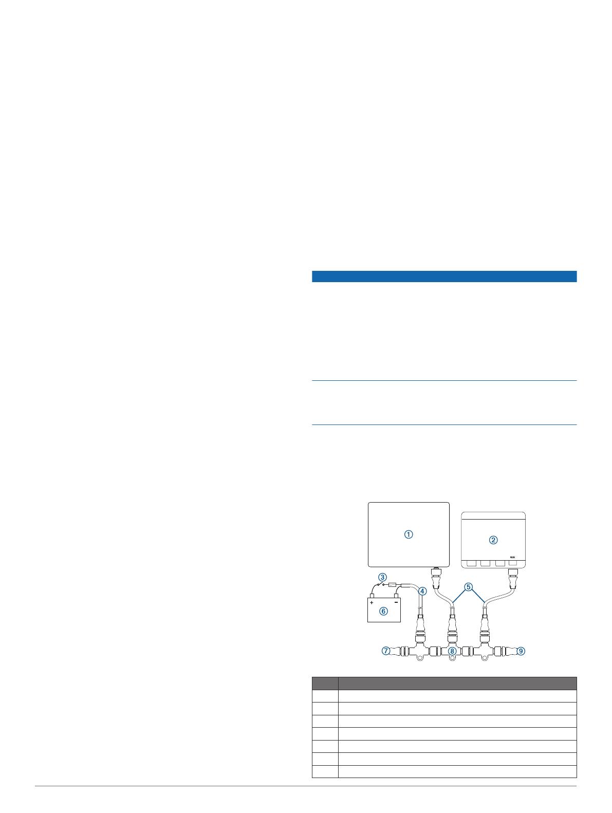
NMEA 2000 Device Connections
NOTICE
If you are connecting this device to an existing NMEA 2000
network, the NMEA 2000 network should already be connected
to power. Do not connect the NMEA 2000 power cable to an
existing NMEA 2000 network, because only one power source
should be connected to a NMEA 2000 network.
If you are connecting this device to an existing NMEA 2000
network or engine network by another manufacturer, you should
install a NMEA 2000 Power Isolator (010-11580-00) between
the existing network and the Garmin devices.
If you are installing a NMEA 2000 power cable, you must
connect it to the boat ignition switch or through another in-line
switch. NMEA 2000 devices will drain your battery if the NMEA
2000 power cable is connected to the battery directly.
To connect this device to your existing NMEA 2000 network, you
must purchase a NMEA 2000 cable and connector.
If you are unfamiliar with NMEA 2000, you should read the
“NMEA 2000 Network Fundamentals” chapter of the Technical
Reference for NMEA 2000 Products. Go to www.garmin.com
/manuals/VHF315/.
Item Description
À
Compatible NMEA 2000 chartplotter or other device
Á
VHF 315 device
Â
Ignition or in-line switch
Ã
NMEA 2000 power cable
Ä
NMEA 2000 drop cable
Å
12 Vdc power source
Æ
NMEA 2000 terminator or backbone cable
3
Item Description
Ç
NMEA 2000 T-connector
È
NMEA 2000 terminator or backbone cable
Connecting the Device to a Remote GPS Antenna
This device must receive GPS information for proper
functionality. You can connect the device to a NMEA 2000
network with a GPS antenna, or you can install a remote GPS
antenna (not included) and connect it to the device.
1
Follow the instructions provided with your external GPS
antenna to install it on your boat correctly.
2
Route the antenna cable to the back of your device, away
from sources of electrical interference.
3
Connect the antenna cable to the GPS port on your device.
Connecting to a Hailer Horn or PA Speaker
You can connect the VHF radio to a hailer horn or public
address (PA) speaker (not included) to use a handset to make
announcements.
1
If necessary, mount the hailer horn or PA speaker according
to the installation instructions provided with the device.
NOTE: To avoid feedback, you should mount the hailer horn
or PA speaker at least 3 m (10 ft.) away from, and facing
away from, a handset.
2
Route or extend the wire from the hailer horn or PA speaker
to the radio.
3
Connect the white wire on the radio wiring harness to the
positive (+) wire from the hailer horn or PA speaker.
4
Connect the green wire on the radio wiring harness to the
negative (-) wire from the hailer horn or PA speaker.
5
Cover the connections with waterproof tape or heat-shrink
tubing.
NMEA
®
0183 Device Connections
This diagram illustrates two-way connections for both sending
and receiving data. You can also use this diagram for one-way
communication. To receive information from a NMEA 0183
device, refer to items
Ê
,
Ë
,
Ì
,
Í
, and
Î
when connecting the
Garmin device. To transmit information to a NMEA 0183 device,
refer to items
Ê
,
Ë
,
Ì
,
Ï
, and
Ð
when connecting the Garmin
device.
Item Description
À
Power source
Á
Power/NMEA 0183 cable
Â
NMEA 0183 device
Item Garmin Wire
Function
Garmin Wire
Color
NMEA 0183
Device Wire
Function
Ê
Power Red Power
Ë
Power ground Black Power ground
Ì
N/A N/A Data ground
Í
RxA (+) Purple TxA (+)
Î
RxB (-) Gray TxB (-)
Ï
TxA (+) Blue RxA (+)
Ð
TxB (-) Brown RxB (-)
Appendix
VHF 315 Series Specifications
Dimensions (H x W x D) 6 x 20.5 x 18.1 cm (2.36 x 8.07 x 7.13 in.)
Weight 1.527 kg (3.37 lb.)
Temperature range Operating: From -15° to 70°C (from 5° to
158°F)
Storage: From -20° to 70°C (from -4° to
158°F)
Compass-safe distance 50 mm (2 in.)
Water rating* IEC 605290 IPX7
Antenna connector S0-239 (50 ohm)
Operating voltage 12.0 Vdc
Current draw Standby: 350 mA
Receive: 600 mA
Transmit: From 2.0 A to 6.0 A (from 1 W to
25 W)
Maximum antenna gain 9 dBi
Antenna port impedance 50 ohm
Hailer output power 20 W at 4 ohm
Hailer horn impedance 4 ohm
NMEA 2000 LEN 1 (50 mA)
*The device withstands incidental exposure to water of up to 1 m
for up to 30 min. For more information, go to www.garmin.com
/waterrating.
GHS 11 Specifications
Dimensions (H×W×D) 154 × 69 × 40 mm (6.1 × 2.7 × 1.6 in.)
Weight (including
cable)
0.698 kg (1.54 lb.)
Temperature range Operating: From -15° to 70°C (from 5° to
158°F)
Storage: From -20° to 70°C (from -4° to
158°F)
Compass-safe distance 70 cm (27.5 in.)
Water rating IEC 60529 IPX7*
Audio output power MEASUREMENT NEEDED ex. 1 W (with
4 ohm at 10% distortion)
*The device withstands incidental exposure to water of up to 1 m
for up to 30 min. For more information, go to www.garmin.com
/waterrating.
Active Speaker Specifications
Dimensions (H×W×D) 111 × 111 × 56.5 mm (6.1 × 2.7 × 1.6 in.)
Weight 349 g (11.22 oz.)
Temperature range Operating: From -15° to 70°C (from 5° to
158°F)
Storage: From -20° to 70°C (from -4° to
158°F)
Compass-safe distance 50 cm (19.6 in.)
Water rating* IEC 60529 IPX7
Audio output power 2.5 W nominal, 4 W max.
*The device withstands incidental exposure to water of up to 1 m
for up to 30 min. For more information, go to www.garmin.com
/waterrating.
© 2018 Garmin Ltd. or its subsidiaries
Garmin
®
and the Garmin logo are trademarks of Garmin Ltd. or its subsidiaries,
registered in the USA and other countries. GHS
is a trademark of Garmin Ltd. or its
subsidiaries. These trademarks may not be used without the express permission of
Garmin.
NMEA
®
and NMEA 2000
®
are registered trademarks of the National Marine Electronics
Association. Other trademarks and trade names are those of their respective owners.
4
support.garmin.com
  • Page 1 1
  • Page 2 2
  • Page 3 3
  • Page 4 4
  • Page 5 5
  • Page 6 6

Garmin VHF 315 Marine Radio Installation guide

Category
Telephone handsets
Type
Installation guide
This manual is also suitable for

Ask a question and I''ll find the answer in the document

Finding information in a document is now easier with AI