Page is loading ...

'HOO
3R ZHU(GJH
&OXVWHU3RZHU(GJH
,167$//$7,21$1'7528%/(6+227,1**8,'(
®
0RGHO&6


'HOO
3RZHU(GJH
&OXVWHU3RZHU(GJH
,167$//$7,21$1'7528%/(6+227,1**8,'(
®

_______________
Information in this document is subject to change without notice.
1997 Dell Computer Corporation. All rights reserved.
Reproduction in any manner whatsoever without the written permission of Dell Computer Corporation is strictly forbidden.
Trademarks used in this text: Dell, the DELL logo, and PowerEdge are registered trademarks and DellWare is a registered service mark of Dell
Computer Corporation; Intel, Pentium, and LANDesk are registered trademarks of Intel Corporation; Microsoft, Windows NT, and MS-DOS are
registered trademarks of Microsoft Corporation; 3Com is a registered trademark of 3Com Corporation.
Other trademarks and trade names may be used in this document to refer to either the entities claiming the marks and names or their products.
Dell Computer Corporation disclaims any proprietary interest in trademarks and trade names other than its own.
December 1997 P/N 17088

v
Safety Instructions
U
se the following safety guidelines to help protect
your computer system from potential damage and to
ensure your own personal safety. See the Preface in this
guide for information about the notational conventions
used in this manual, including the distinction between
warnings, cautions, and notes.
B
efore You Begin
Observe the following warnings while servicing this
system:
WARNING: The power supplies in this computer
system produce high voltages and energy hazards,
which can cause bodily harm. Only trained service
technicians are authorized to remove the computer
covers and access any of the components inside the
computer.
WARNING: This system may have more than one
power supply cable. To reduce the risk of electrical
shock, a trained service technician must disconnect
all power supply cables before servicing the system.
ADVARSEL: Dette system kan have mere end et
strømforsyningskabel. For at reducere risikoen for
elektrisk stød, bør en professionel servicetekniker
frakoble alle strømforsyningskabler, før systemet
serviceres.
VAROITUS: Tässä järjestelmässä voi olla useampi
kuin yksi virtajohto. Sähköiskuvaaran pie-
nentämiseksi ammattitaitoisen huoltohenkilön on
irrotettava kaikki virtajohdot ennen järjestelmän
huoltamista.
ADVARSEL! Det er mulig at dette systemet har
mer enn én strømledning. Unngå fare for støt: En
erfaren servicetekniker må koble fra alle strømled-
ninger før det utføres service på systemet.
VARNING: Detta system kan ha flera nätkablar.
En behörig servicetekniker måste koppla loss alla
nätkablar innan service utförs för att minska
risken för elektriska stötar.

vi
W
hen Working Inside the
Computer
Before taking the covers off of the computer, perform the
following steps in the sequence indicated:
1. Turn off the computer and any peripherals.
2. Disconnect the computer and peripherals from
their power sources. Also, disconnect any tele-
phone or telecommunications lines from the
computer.
Doing so reduces the potential for personal injury or
shock.
3. Touch an unpainted metal surface on the com-
puter chassis, such as the power supply, before
touching anything inside the computer.
While you work, periodically touch an unpainted
metal surface on the computer chassis to dissipate
any static electricity that might harm internal
components.
In addition, take note of these safety guidelines when
appropriate:
•
To help avoid possible damage to the system board,
wait 5 seconds after turning off the system before
removing a component from the system board or dis-
connecting a peripheral device from the computer.
•
When you disconnect a cable, pull on its connector
or on its strain-relief loop, not on the cable itself.
Some cables have a connector with locking tabs; if
you are disconnecting this type of cable, press in on
the locking tabs before disconnecting the cable. As
you pull connectors apart, keep them evenly aligned
to avoid bending any connector pins. Also, before
you connect a cable, make sure both connectors are
correctly oriented and aligned.
•
Handle components and cards with care. Don’t touch
the components or contacts on a card. Hold a card by
its edges or by its metal mounting bracket. Hold a
component such as a microprocessor chip by its
edges, not by its pins.
P
rotecting Against Electrostatic
Discharge
Static electricity can harm delicate components inside the
computer. To prevent static damage, discharge static elec-
tricity from your body before you touch any of the
computer’s electronic components, such as the micro-
processor. You can do so by touching an unpainted metal
surface on the computer chassis.
As you continue to work inside the computer, periodi-
cally touch an unpainted metal surface to remove any
static charge your body may have accumulated.
You can also take the following steps to prevent damage
from electrostatic discharge (ESD):
•
When unpacking a static-sensitive component from
its shipping carton, do not remove the component’s
antistatic packing material until you are ready to
install the component in the computer. Just before
unwrapping the antistatic packaging, be sure to dis-
charge static electricity from your body.
•
When transporting a sensitive component, first place
it in an antistatic container or packaging.
•
Handle all sensitive components in a static-safe area.
If possible, use antistatic floor pads and workbench
pads.
The following caution may appear throughout this docu-
ment to remind you of these precautions:
WAR NI NG
There is a danger of a new battery exploding if it is
incorrectly installed. Replace the battery only with
the same or equivalent type recommended by the
manufacturer. Discard used batteries according to
the manufacturer’s instructions.
CAUTION: See “Protecting Against Electrostatic
Discharge” in the safety instructions at the front of
this guide.

vii
W
hen Using the Computer
System
As you use the computer system, observe the following
safety guidelines:
•
If your computer has a voltage selection switch on
the power supply, be sure the switch is set to match
the alternating current (AC) power available at your
location:
— 115 volts (V)/60 hertz (Hz) in most of North and
South America and some Far Eastern countries
such as Japan, South Korea, and Taiwan
— 230 V/50 Hz in most of Europe, the Middle
East, and the Far East
•
Be sure the monitor and attached peripherals are
electrically rated to operate with the AC power avail-
able in your location.
•
To help prevent electric shock, plug the computer
and peripheral power cables into properly grounded
power sources. These cables are equipped with
three-prong plugs to ensure proper grounding. Do
not use adapter plugs or remove the grounding prong
from a cable. If you must use an extension cable, use
a three-wire cable with properly grounded plugs.
•
To help protect the computer system from sudden,
transient increases and decreases in electrical power,
use a surge suppressor, line conditioner, or un-
interruptible power supply (UPS).
•
Be sure nothing rests on the computer system’s
cables and that the cables are not located where they
can be stepped on or tripped over.
•
Do not push any objects into the openings of the
computer. Doing so can cause fire or electric shock
by shorting out interior components.
•
Keep the computer away from radiators and heat
sources. Also, do not block cooling vents. Avoid
placing loose papers underneath the computer, and
do not place the computer in a closed-in wall unit or
on a rug.

viii

ix
Preface
A
bout This Guide
This guide provides information about installing, config-
uring, and troubleshooting the hardware and software
components of the Dell PowerEdge Cluster. This docu-
ment addresses the use of two PowerEdge 4200 server
systems and one or two PowerEdge Scalable Disk Sys-
tem 100 (SDS 100) storage systems in the PowerEdge
Cluster. Dell plans future clustering products that will
incorporate other products in the Dell server family. User
documentation specific to those systems will be available
as new cluster products are released.
This guide addresses two audience levels:
•
Users and system installers who will perform general
setup, cabling, and configuration of the PowerEdge
Cluster
•
Trained service technicians who will perform more
extensive installations such as firmware upgrades
and installation of required expansion cards
This guide identifies the appropriate audience for each
topic being discussed.
The chapters and appendixes in this guide are summa-
rized as follows:
•
Chapter 1, “Getting Started,” provides an overview
of the PowerEdge Cluster and outlines the steps for
installing a new PowerEdge Cluster system or modi-
fying an existing PowerEdge system into a
PowerEdge Cluster.
•
Chapter 2, “Cabling the Cluster Hardware,” provides
instructions for properly cabling the system hard-
ware components.
•
Chapter 3, “Configuring the Cluster Software,”
describes the software configuration options that
must be specified to properly set up the cluster
system.
•
Chapter 4, “Running Applications on a Cluster” pro-
vides general information about running applications
on the PowerEdge Cluster.
•
Chapter 5, “Troubleshooting,” provides information
to help you troubleshoot problems with the cluster’s
installation and configuration.
•
Appendix A, “Upgrading to a Cluster Configura-
tion,” provides specific information to service
technicians about upgrading existing system hard-
ware and software to a cluster configuration.
•
Appendix B, “Stand-Alone and Rack Configura-
tions,” lists the Dell-supported stand-alone and rack
configurations and provides instructions for install-
ing the network switch in a rack.
•
Appendix C, “Cluster Data Sheet,” provides a form
for gathering and recording important information
about your PowerEdge Cluster.
•
Appendix D, “PowerEdge Cluster Configuration
Matrix,” describes the configuration matrix form,
which is used to record information about the cluster
hardware such as service tag numbers and types of
adapters installed in the cluster node PCI slots.
•
Appendix E, “Regulatory Compliance,” lists the
regulatory standards with which the PowerEdge
Cluster has been tested and certified for compliance.
•
Appendix F, “Safety Information for Technicians,”
provides important safety warnings about electro-
static discharge (ESD).

x
•
Appendix G, “Warranties and Return Policy,”
describes the warranty information pertaining to the
system.
O
ther Documentation You May
Need
You may need to reference the following documentation
when performing the procedures in this guide:
•
The Dell PowerEdge 4200 Systems User’s Guide,
which describes system features and technical speci-
fications, small computer system interface (SCSI)
device drivers, the System Setup program, software
support, and the system configuration utility.
•
The Dell PowerEdge SDS 100 Storage System
Installation and Service Guide, which provides
installation and operation instructions for the
PowerEdge SDS 100 storage system.
•
The Intel LANDesk Server Manager software,
which includes a CD containing the server manager
software and the following documents: LANDesk
Server Manager Setup Guide, LANDesk Server
Manager User’s Guide, LANDesk Server Control
Installation and User’s Guide, and LANDesk Server
Monitor Module Installation and User’s Guide.
•
The Dell Hardware Instrumentation Package for
Intel LANDesk Server Manager User’s Guide, which
provides installation and configuration procedures as
well as the alert messages issued by this server man-
agement software.
•
The Using the Dell Server Assistant CD document,
which provides instructions for using the Dell Server
Assistant CD.
You may also have one or more of the following
documents:
•
The Dell PowerEdge Rack-Mountable Solutions
Installation Guide, Dell PowerEdge 4xxx and 6xxx
Systems Rack Kit Installation Guide, and Dell
PowerEdge SDS 100 Storage System Rack Installation
Guide, which provide detailed instructions for install-
ing the cluster components in a rack.
•
The following documents accompany the Dell
PowerEdge Expandable Redundant Array of Inex-
pensive Disks (RAID) Controller: Dell PowerEdge
Expandable RAID Controller User’s Guide, Dell
PowerEdge Expandable RAID Controller Client
User’s Guide, Dell PowerEdge Expandable RAID
Controller General Alert Server User’s Guide, and
Dell PowerEdge Expandable RAID Controller Bat-
tery Backup Module User’s Guide.
•
Documentation for the Microsoft Windows NT
Server Enterprise Edition operating system is
included with the system if you ordered the operat-
ing system software from Dell. This documentation
describes how to install (if necessary), configure,
and use the operating system software.
•
Documentation is included with any options you
purchase separately from the system. This documen-
tation includes information that you need to
configure and install these options in the Dell
computer.
•
Technical information files—sometimes called
“readme” files—may be installed on the hard-disk
drive to provide last-minute updates about technical
changes to the system or advanced technical refer-
ence material intended for experienced users or
technicians.
NOTE: Documentation updates are sometimes included
with the system to describe changes to the system or soft-
ware. Always read these updates
before
consulting any
other documentation because the updates often contain infor-
mation that supersedes the information in the other
documents.
N
otational Conventions
The following subsections list notational conventions
used in this document.
Warnings, Cautions, and Notes
Throughout this guide, there may be blocks of text
printed in bold type within boxes or in italic type. These
blocks are warnings, cautions, and notes, and they are
used as follows:
WARNING: A WARNING indicates the potential
for bodily harm and tells you how to avoid the
problem.

xi
NOTE: A NOTE indicates important information that
helps you make better use of the computer system.
Typographical Conventions
The following list defines (where appropriate) and illus-
trates typographical conventions used as visual cues for
specific elements of text throughout this document:
•
Keycaps, the labeling that appears on the keys on a
keyboard, are enclosed in angle brackets.
Example: <Enter>
•
Key combinations are a series of keys to be pressed
simultaneously (unless otherwise indicated) to per-
form a single function.
Example: <Ctrl><Alt><Enter>
•
Commands presented in lowercase bold are for refer-
ence purposes only and are not intended to be typed
when referenced.
Example: “Use the format command to . . . ”
In contrast, commands presented in the Courier New
font are part of an instruction and intended to be
typed.
Example: “Type format a: to format the diskette
in drive A.”
•
Filenames and directory names are presented in
lowercase bold.
Examples: autoexec.bat and c:\windows
•
Syntax lines consist of a command and all its
possible parameters. Commands are displayed in
lowercase bold; variable parameters (those for which
you substitute a value) are displayed in lowercase
italics; constant parameters are displayed in lower-
case bold. The brackets indicate items that are
optional.
Example: del [drive:] [path] filename [/p]
•
Command lines consist of a command and may
include one or more of the command’s possible
parameters. Command lines are presented in the
Courier New font.
Example: del c:\myfile.doc
•
Screen text is text that appears on the screen of your
monitor or display. It can be a system message, for
example, or it can be text that you are instructed to
type as part of a command (referred to as a command
line). Screen text is presented in the Courier New
font.
Example: The following message appears on your
screen:
No boot device available
Example: “Type md c:\dos and press <Enter>.”
•
Variables are placeholders for which you substitute a
value. They are presented in italics.
Example: SIMMn (where n represents the SIMM socket
designation)
CAUTION: A CAUTION indicates either poten-
tial damage to hardware or loss of data and tells
you how to avoid the problem.

xii

xiii
Contents
Chapter 1
Getting Started. . . . . . . . . . . . . . . . . . . . . . . . . . . . . . . . . . . . . . . . . 1-1
PowerEdge Cluster Components. . . . . . . . . . . . . . . . . . . . . . . . . . . . . . . . . . . . . . . . . 1-1
Minimum System Requirements. . . . . . . . . . . . . . . . . . . . . . . . . . . . . . . . . . . . . . . . . 1-2
Basic Installation Procedure . . . . . . . . . . . . . . . . . . . . . . . . . . . . . . . . . . . . . . . . . . . . 1-3
Adding Peripherals Required for Clustering . . . . . . . . . . . . . . . . . . . . . . . . . . . . 1-4
Setting Up the Cluster Hardware . . . . . . . . . . . . . . . . . . . . . . . . . . . . . . . . . . . . . 1-5
Cabling the Cluster Hardware . . . . . . . . . . . . . . . . . . . . . . . . . . . . . . . . . . . . . . . 1-5
Updating System BIOS/Firmware for Clustering . . . . . . . . . . . . . . . . . . . . . . . . 1-5
Setting Up the Shared Storage Subsystem Hard-Disk Drives . . . . . . . . . . . . . . . 1-6
Setting Up the Internal SCSI Hard-Disk Drives . . . . . . . . . . . . . . . . . . . . . . . . . 1-6
Installing and Configuring Windows NT Server Enterprise Edition. . . . . . . . . . 1-6
Installing and Configuring the Microsoft Cluster Server Software. . . . . . . . . . . 1-6
Installing PowerEdge Cluster Applications . . . . . . . . . . . . . . . . . . . . . . . . . . . . . 1-6
Checking the System . . . . . . . . . . . . . . . . . . . . . . . . . . . . . . . . . . . . . . . . . . . . . . 1-6
Chapter 2
Cabling the Cluster Hardware. . . . . . . . . . . . . . . . . . . . . . . . . . . . . 2-1
Cluster Cabling . . . . . . . . . . . . . . . . . . . . . . . . . . . . . . . . . . . . . . . . . . . . . . . . . . . . . . 2-1
One Shared Storage Subsystem Cabled to a Cluster. . . . . . . . . . . . . . . . . . . . . . . . . . 2-1
Two SDS 100 Storage Systems Cabled to a Single RAID Controller . . . . . . . . . . . . 2-3
Two SDS 100 Storage Systems Cabled to Dual RAID Controllers . . . . . . . . . . . . . . 2-4
SMB Cabling. . . . . . . . . . . . . . . . . . . . . . . . . . . . . . . . . . . . . . . . . . . . . . . . . . . . . . . . 2-5
NIC Cabling . . . . . . . . . . . . . . . . . . . . . . . . . . . . . . . . . . . . . . . . . . . . . . . . . . . . . . . . 2-5
Power Cabling. . . . . . . . . . . . . . . . . . . . . . . . . . . . . . . . . . . . . . . . . . . . . . . . . . . . . . . 2-7
Mouse, Keyboard, and Monitor Cabling. . . . . . . . . . . . . . . . . . . . . . . . . . . . . . . . . . . 2-7
Disconnecting SCSI Cables While the Cluster Is Running. . . . . . . . . . . . . . . . . . . . . 2-7

xiv
Chapter 3
Configuring the Cluster Software . . . . . . . . . . . . . . . . . . . . . . . . . 3-1
Low-Level Software Configuration . . . . . . . . . . . . . . . . . . . . . . . . . . . . . . . . . . . . . . 3-1
Important System Warning . . . . . . . . . . . . . . . . . . . . . . . . . . . . . . . . . . . . . . . . . 3-1
SCSI Host Adapter IDs . . . . . . . . . . . . . . . . . . . . . . . . . . . . . . . . . . . . . . . . . . . . 3-2
Disabling a RAID Controller BIOS . . . . . . . . . . . . . . . . . . . . . . . . . . . . . . . . . . 3-2
RAID Level for the Shared Storage Subsystem(s) . . . . . . . . . . . . . . . . . . . . . . . 3-2
RAID Level for the Internal Hard-Disk Drives (Optional). . . . . . . . . . . . . . . . . 3-2
High-Level Software Configuration. . . . . . . . . . . . . . . . . . . . . . . . . . . . . . . . . . . . . . 3-3
Installing Intel LANDesk
Server Manager . . . . . . . . . . . . . . . . . . . . . . . . . . . . . 3-3
Choosing a Domain Model . . . . . . . . . . . . . . . . . . . . . . . . . . . . . . . . . . . . . . . . . 3-3
Static IP Addresses . . . . . . . . . . . . . . . . . . . . . . . . . . . . . . . . . . . . . . . . . . . . . . . 3-3
IPs and Subnet Masks . . . . . . . . . . . . . . . . . . . . . . . . . . . . . . . . . . . . . . . . . . . . . 3-3
Configuring Separate Networks on a Cluster . . . . . . . . . . . . . . . . . . . . . . . . . . . 3-3
Changing the IP Address of a Cluster Node . . . . . . . . . . . . . . . . . . . . . . . . . . . . 3-4
Naming and Formatting Shared Drives. . . . . . . . . . . . . . . . . . . . . . . . . . . . . . . . 3-4
Driver for the RAID Controller. . . . . . . . . . . . . . . . . . . . . . . . . . . . . . . . . . . . . . 3-4
Updating the NIC Driver. . . . . . . . . . . . . . . . . . . . . . . . . . . . . . . . . . . . . . . . . . . 3-5
Adjusting the Paging File Size and Registry Sizes. . . . . . . . . . . . . . . . . . . . . . . 3-5
Verifying the Cluster Functionality . . . . . . . . . . . . . . . . . . . . . . . . . . . . . . . . . . . . . . 3-5
1 x 8 Mode on the SDS 100 Storage System . . . . . . . . . . . . . . . . . . . . . . . . . . . 3-5
SCSI Controller IDs . . . . . . . . . . . . . . . . . . . . . . . . . . . . . . . . . . . . . . . . . . . . . . 3-6
Cluster Domain . . . . . . . . . . . . . . . . . . . . . . . . . . . . . . . . . . . . . . . . . . . . . . . . . . 3-6
RAID Controller Driver . . . . . . . . . . . . . . . . . . . . . . . . . . . . . . . . . . . . . . . . . . . 3-6
Shared Storage Subsystem Drive Letters . . . . . . . . . . . . . . . . . . . . . . . . . . . . . . 3-6
Cluster Network Communications . . . . . . . . . . . . . . . . . . . . . . . . . . . . . . . . . . . 3-6
Cluster Service . . . . . . . . . . . . . . . . . . . . . . . . . . . . . . . . . . . . . . . . . . . . . . . . . . 3-7
Availability of Cluster Resources . . . . . . . . . . . . . . . . . . . . . . . . . . . . . . . . . . . . 3-7
Uninstalling Microsoft Cluster Server . . . . . . . . . . . . . . . . . . . . . . . . . . . . . . . . . . . . 3-7
Removing a Node From a Cluster . . . . . . . . . . . . . . . . . . . . . . . . . . . . . . . . . . . . . . . 3-7
Setting Up the Quorum Resource. . . . . . . . . . . . . . . . . . . . . . . . . . . . . . . . . . . . . . . . 3-8
Using the ftdisk Driver. . . . . . . . . . . . . . . . . . . . . . . . . . . . . . . . . . . . . . . . . . . . . . . . 3-8
Cluster RAID Controller Functionality . . . . . . . . . . . . . . . . . . . . . . . . . . . . . . . . . . . 3-8
Rebuild Function Does Not Complete After Reboot or Power Loss . . . . . . . . . 3-8
Rebuild Rate Not Adjustable on
Cluster-Enabled RAID Controller. . . . . . . . . . . . . . . . . . . . . . . . . . . . . . . . . . . . 3-8
Using the Maximize Feature in PowerEdge RAID Console. . . . . . . . . . . . . . . . 3-8
Rebuild Operation in RAID Console . . . . . . . . . . . . . . . . . . . . . . . . . . . . . . . . . 3-9

xv
Chapter 4
Running Applications on a Cluster . . . . . . . . . . . . . . . . . . . . . . . . 4-1
Setting Up Applications
Software to Run on the Cluster . . . . . . . . . . . . . . . . . . . . . . . . . . . . . . . . . . . . . . . . . . 4-1
Internet Information Server Service. . . . . . . . . . . . . . . . . . . . . . . . . . . . . . . . . . . 4-1
File Share Service . . . . . . . . . . . . . . . . . . . . . . . . . . . . . . . . . . . . . . . . . . . . . . . . 4-2
Print Spooler Service . . . . . . . . . . . . . . . . . . . . . . . . . . . . . . . . . . . . . . . . . . . . . . 4-3
Using the Rediscovery Application in Intel LANDesk. . . . . . . . . . . . . . . . . . . . . . . . 4-4
Running chkdsk /f on a Quorum Disk. . . . . . . . . . . . . . . . . . . . . . . . . . . . . . . . . . . . . 4-5
Tape Backup for Clustered Systems . . . . . . . . . . . . . . . . . . . . . . . . . . . . . . . . . . . . . . 4-5
Chapter 5
Troubleshooting. . . . . . . . . . . . . . . . . . . . . . . . . . . . . . . . . . . . . . . . 5-1
Appendix A
Upgrading to a Cluster Configuration . . . . . . . . . . . . . . . . . . . . . . A-1
Checking Your Existing Hardware . . . . . . . . . . . . . . . . . . . . . . . . . . . . . . . . . . . . . . .A-1
Adding Expansion Cards for a Cluster Upgrade. . . . . . . . . . . . . . . . . . . . . . . . . . . . .A-1
Mounting, Cabling, and Configuring the Cluster Hardware. . . . . . . . . . . . . . . . . . . .A-2
Installing and Configuring the Cluster Software. . . . . . . . . . . . . . . . . . . . . . . . . . . . .A-3
Upgrading the PowerEdge 4200 Firmware . . . . . . . . . . . . . . . . . . . . . . . . . . . . .A-3
Upgrading the PowerEdge SDS 100 Storage System Firmware . . . . . . . . . . . . .A-3
Setting the Cluster Mode With BIOS Setup . . . . . . . . . . . . . . . . . . . . . . . . . . . .A-3
Installing and Configuring NICs. . . . . . . . . . . . . . . . . . . . . . . . . . . . . . . . . . . . . . . . .A-3
Appendix B
Stand-Alone and Rack Configurations . . . . . . . . . . . . . . . . . . . . . B-1
Power Requirements of the PowerEdge Cluster . . . . . . . . . . . . . . . . . . . . . . . . . . . . .B-1
Supported Stand-Alone Configurations . . . . . . . . . . . . . . . . . . . . . . . . . . . . . . . . . . .B-2
Rack Safety Notices . . . . . . . . . . . . . . . . . . . . . . . . . . . . . . . . . . . . . . . . . . . . . . . . . .B-2
Kit Installation Restrictions . . . . . . . . . . . . . . . . . . . . . . . . . . . . . . . . . . . . . . . . .B-2
Rack Stabilizer Feet . . . . . . . . . . . . . . . . . . . . . . . . . . . . . . . . . . . . . . . . . . . . . . .B-2
Supported Rack Configuration . . . . . . . . . . . . . . . . . . . . . . . . . . . . . . . . . . . . . . . . . .B-5
Rack-Mounting the Network Switch. . . . . . . . . . . . . . . . . . . . . . . . . . . . . . . . . . . . . .B-6
Appendix C
Cluster Data Sheet. . . . . . . . . . . . . . . . . . . . . . . . . . . . . . . . . . . . . . C-1
Appendix D
PowerEdge Cluster Configuration Matrix . . . . . . . . . . . . . . . . . . . D-1

xvi
Appendix E
Regulatory Compliance. . . . . . . . . . . . . . . . . . . . . . . . . . . . . . . . . . E-1
Regulatory Standards . . . . . . . . . . . . . . . . . . . . . . . . . . . . . . . . . . . . . . . . . . . . . . . . . E-1
CE Notice . . . . . . . . . . . . . . . . . . . . . . . . . . . . . . . . . . . . . . . . . . . . . . . . . . . . . . . . . . E-1
Safety Standard . . . . . . . . . . . . . . . . . . . . . . . . . . . . . . . . . . . . . . . . . . . . . . . . . . E-1
EMC Standards . . . . . . . . . . . . . . . . . . . . . . . . . . . . . . . . . . . . . . . . . . . . . . . . . . E-1
Appendix F
Safety Information for Technicians . . . . . . . . . . . . . . . . . . . . . . . . F-1
Appendix G
Warranties and Return Policy. . . . . . . . . . . . . . . . . . . . . . . . . . . . . G-1
Limited Three-Year Warranty (U.S. and Canada Only) . . . . . . . . . . . . . . . . . . . . . . G-1
Coverage During Year One. . . . . . . . . . . . . . . . . . . . . . . . . . . . . . . . . . . . . . . . . G-1
Coverage During Years Two and Three . . . . . . . . . . . . . . . . . . . . . . . . . . . . . . . G-2
General . . . . . . . . . . . . . . . . . . . . . . . . . . . . . . . . . . . . . . . . . . . . . . . . . . . . . . . . G-2
“Total Satisfaction” Return Policy (U.S. and Canada Only) . . . . . . . . . . . . . . . . . . . G-2
Index
Figures
Figure 1-1. PowerEdge Cluster Layout . . . . . . . . . . . . . . . . . . . . . . . . . . . . . . . . 1-2
Figure 1-2. Back View of a PowerEdge 4200 Cluster Node . . . . . . . . . . . . . . . . 1-5
Figure 2-1. Cabling a Clustered System With One PowerEdge SDS 100
Storage System. . . . . . . . . . . . . . . . . . . . . . . . . . . . . . . . . . . . . . . . . . 2-2
Figure 2-2. Cabling Single RAID Controllers to Two PowerEdge SDS 100
Storage Systems. . . . . . . . . . . . . . . . . . . . . . . . . . . . . . . . . . . . . . . . . 2-3
Figure 2-3. Cabling Dual RAID Controllers to Two PowerEdge SDS 100
Storage Systems. . . . . . . . . . . . . . . . . . . . . . . . . . . . . . . . . . . . . . . . . 2-4
Figure 2-4. SMB Cable Connected to One SDS 100 Storage System . . . . . . . . . 2-5
Figure 2-5. SMB Cables Connected to Two SDS 100 Storage Systems . . . . . . . 2-5
Figure 2-6. Cabling the Network Switch . . . . . . . . . . . . . . . . . . . . . . . . . . . . . . . 2-6
Figure 2-7. PowerEdge Cluster Power Cabling . . . . . . . . . . . . . . . . . . . . . . . . . . 2-8
Figure A-1. Back View of a PowerEdge 4200 Cluster Node . . . . . . . . . . . . . . . . A-2
Figure B-1. Supported Stand-Alone Configurations With One SDS 100
Storage System. . . . . . . . . . . . . . . . . . . . . . . . . . . . . . . . . . . . . . . . . . B-3
Figure B-2. Supported Stand-Alone Configurations With Two SDS 100
Storage Systems. . . . . . . . . . . . . . . . . . . . . . . . . . . . . . . . . . . . . . . . . B-4
Figure B-3. Supported Rack Configuration . . . . . . . . . . . . . . . . . . . . . . . . . . . . . B-5

xvii
Figure B-4. Attaching the Rack-Mounting Hardware on the Network Switch . . .B-6
Figure D-1. PowerEdge Cluster Configuration Matrix . . . . . . . . . . . . . . . . . . . . .D-2
Table
Table 5-1. Troubleshooting . . . . . . . . . . . . . . . . . . . . . . . . . . . . . . . . . . . . . . . . . 5-1

xviii

Getting Started 1-1
Chapter 1
Getting Started
T
he Dell
®
PowerEdge
®
Cluster is an enterprise system
that implements clustering technology based on the
Microsoft
®
Windows NT
®
Server, Enterprise Edition 4.0
operating system and Microsoft Windows NT Cluster
Server. The Dell PowerEdge Cluster provides the follow-
ing benefits in meeting the needs of mission-critical
network applications:
•
High availability of system services and resources to
network clients
•
Redundant storage of application data
•
Failure recovery for cluster applications
•
Capability to repair, maintain, or upgrade a cluster
server without taking the whole cluster off-line
•
Sharing of processing and communication work load
between the two servers
The term cluster refers to two or more server systems
(referred to as nodes) that are interconnected with appro-
priate hardware and software to provide a single point of
continuous access to network services (for example, file
service, database applications, resources, and so on) for
network clients. Each cluster node is configured with
software and network resources that enable it to interact
with the other node to provide a mutual redundancy of
operation and application processing. Because the servers
interact in this way, they appear as a single system to the
network clients.
As an integrated system, the PowerEdge Cluster is
designed to handle most hardware failures and downtime
dynamically. In the event that one of the cluster nodes
fails or experiences downtime, the processing work load
of the failed node switches over (or fails over) to the
remaining node in the cluster. This fail-over capability
enables the cluster system to keep network resources and
applications up and running on the network while the
failed node is taken off-line, repaired, and brought back
online. The overall impact of a node failure to network
operation is minimal.
P
owerEdge Cluster Components
The Dell PowerEdge Cluster consists of two Dell Power-
Edge 4200 systems (the cluster nodes) equipped with one
or two Dell PowerEdge Expandable redundant array of
inexpensive disks (RAID) Controllers and two network
interface controllers (NICs) to provide a dedicated node-
to-node network interconnection and a regular Ethernet
local area network (LAN) connection. Each server has
shared Ultra/Wide small computer system interface
(SCSI) connections to one or more Dell PowerEdge
Scalable Disk System (SDS 100) storage system(s).
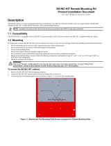
Figure 1-1 shows a layout of the PowerEdge Cluster
components and their interconnections.
Each component of the PowerEdge Cluster has a mini-
mum system requirement. The following section lists and
describes the minimum system requirements for the
PowerEdge Cluster.

1-2 Dell PowerEdge Cluster (PowerEdge 4200) Installation and Troubleshooting Guide
Figure 1-1. PowerEdge Cluster Layout
M
inimum System Requirements
NOTE: If you are upgrading an existing system to a
PowerEdge Cluster, check this list to ensure that your
upgrade meets these requirements.
The PowerEdge Cluster requires the following minimum
system hardware configuration:
•
Two PowerEdge 4200 systems with the following
configuration:
— One or two 233-megahertz (MHz), one or two
266-MHz, or one or two 300-MHz Intel
®
Pentium
®
II microprocessors with at least
512 kilobytes (KB) of level 2 (L2) cache.
—
128 megabytes (MB) of random-access memory
(RAM).
— A minimum of one PowerEdge Expandable
RAID Controller in each PowerEdge system
with 16 MB of
single in-line memory module
(SIMM) memory. This controller must have
cluster-specific firmware and must be installed
in Peripheral Component Interconnect [PCI]
slot 7. A second cluster RAID controller can be
added to slot 5, but the first cluster RAID
controller must be installed in slot 7.
— Two 4-GB internal SCSI hard-disk drives (three
drives are required for an internal RAID 5
configuration).
— Two Ethernet NICs, installed in PCI slots 4 and
8. The LAN-connected NIC resides in PCI slot
8, and the node-to-node interconnect NIC occu-
pies slot 4.
•
Power cabling and distribution components required:
— For the Americas: Two Power Techniques
power strips with Type B plugs, Model P905200
— For Europe: One or two Marway power distri-
bution units (PDUs), Model MPD-411013 or
two Power Techniques power strips with Type B
plugs, Model P906200
•
One or two SDS 100 storage system(s) for the shared
disk resource with the following configuration:
— Cluster-specific basic input/output system
(BIOS) upgrade for the PowerEdge systems for
turning the SDS 100 storage system backplane
into a 1 x 8 mode (one SCSI channel with up to
eight hard-disk drives) when two RAID control-
lers are present.
3Com SuperStack II
Switch 3000 TX
PowerEdge 4200
systems (2)
PowerEdge SDS 100
storage systems (1 or 2)
with RAID
/