LCD8205

NEC LCD8205 Miscellaneous Information

  • Hello! I am an AI chatbot trained to assist you with the NEC LCD8205 Miscellaneous Information. I’ve already reviewed the document and can help you find the information you need or explain it in simple terms. Just ask your questions, and providing more details will help me assist you more effectively!
NEC MultiSync LCD8205
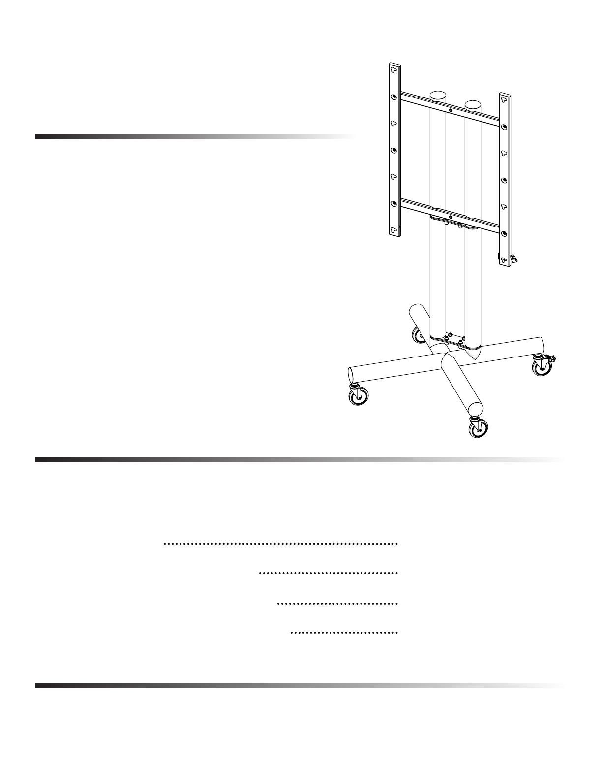
LCD8205-FSK Floor Stand Kit
User Instructions
-It is the responsibility of the installer to ensure this
product is properly assembled.
-The Floor Stand Kit is designed to allow exible
placement of the LCD8205, in a variety of location.
Highlights
-Ultra-sturdy, all-steel construction.
-Black powdercoat nish.
-Includes leveling feet or castors.
-For use with the LCD8205 in landscape or
portrait mode.
-Easily disassembles into three main pieces.
Page 1
Contents
Components Page 2
Assembling the Floor Stand Kit Pages 3-4
Installing the LCD8205 mount rails Pages 5-6
Installing, and securing, the LCD8205 Pages 6-7
Components
Page 2
Includes all pieces shipped with Floor Stand Kit
9
2
1
3
10
11
7
8
5
6
4
ITEM NO
QTY
DESCRIPTION
1 1
MIDDDLE SECTION
2 1
TOP SECTION
3 1
BASE
4 2
KEYHOLE MOUNT TUBE
5 1
LOCK PIN
6 1
PADLOCK
7 4
1/2”-13 HEX NUT
8 14
1/2” FLAT WASHER
9 14
1/2”-13 x 1 1/4” BOLT
10 2
5” CASTOR w/BRAKE
11 2
5” CASTOR
Assembling The Floor Stand Kit
Process begins with installation of castors or leveling feet.
Page 3
-Step One
Conrm that 1/2”-13 hex-nuts are threaded onto the stem of the castors. If not,
be sure to do so. Once the hex-nuts are installed, the castors can be threaded
into the base of the Floor Stand Kit. Reminder, installation of leveling feet is
identical, except the feet need to be adjusted to ensure the stand will sit level.
-Step Two
Attach middle-section to the base. Slip the middle-section onto the positioning
cylinders. Install the four 1/2”-13 Allen head bolts, and 1/2” at washers.
Assembling The Floor Stand Kit
Continued from previous page.
Page 4
-Step Three
Attach top-section to the middle-section. Slip the top-section onto the position-
ing cylinders. Install the four 1/2”-13 Allen head bolts, and 1/2” at washers.
Installing The LCD8205 Mount Rails
Continued from previous page.
Page 5
-Step Four
Before the display mounts can be installed, the orientation of the LCD8205 must
be determined.
-Step Five
Installing the display mounts in portrait orientation. Use six 1/2”-13 Allen head
bolts and at washers. Be sure that keyholes match the illustration.
Portrait
Landscape
Installing The LCD8205 Mount Rails
Continued from previous page.
Page 6
-Step Six
Installing the display mounts in landscape orientation. Use six 1/2”-13 Allen
head bolts and at washers. Be sure that keyholes match the illustration.
-Step Seven
Install the display in the appropriate orientation.
Securing The LCD8205
Continued from previous page.
Page 7
-Step Eight(nal step)
Install lock pin, and padlock. Shown without display mounted for ease of visualization.
/