USERS’ INSTALLATION
OPERATION and
MAINTENANCE MANUAL
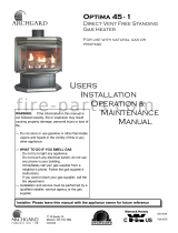
Optima 45 - 3
Direct Vent Free Standing
Gas Heater
For use with Natural Gas or Propane*
Do not store or use gasoline or other flammable
vapors and liquids in the vicinity of this or any
other appliance.
WHAT TO DO IF YOU SMELL GAS:
* Do not try to light any appliance.
* Do not touch any electrical switch; do not use
any phone in your building.
* Immediately call your gas supplier from a
neighbor’s phone. Follow the gas supplier’s
instructions.
* If you cannot reach your gas supplier, call the
fire department.
Installation and service must be performed by a
qualified installer, service agency or the gas
supplier.
WARNING: If the information in this manual is
not followed exactly, fire or explosion may result
causing property damage, personal injury or loss
of life.
Installer: Please leave this manual with the appliance owner for future reference
200-0169
FEBRUARY 2005
This appliance may be installed in an after-market,
permanently located, manufactured home (USA
only) or mobile home, where not prohibited by local
codes.
This appliance is only for use with the type of gas
indicated on the rating plate. This appliance is not
convertible for use with other gases, unless a
certified kit is used.
7116 Beatty Dr
Mission, BC V2V 6B4
Canada
*Conversion Kit Required for Propane Use


INTRODUCTION
Congratulations on choosing an Archgard fireplace!
The Optima 45-3 is one of the most advanced direct vent fireplace heaters available. It is
solidly designed using the latest technology and manufactured to the highest quality. It is our
aim to provide you with an appliance for many trouble-free years of reliable service.
The following are just some of the many features within your new gas fireplace:
Heater Classification The Optima 45-3 is classified as a heating appliance. In
conjunction with an optional thermostat, the Optima 45-3 can
be operated continuously for zone heating.
High Efficiency The Optima 45-3 has one of the highest efficiencies of any gas
fireplace, which means that it is less expensive to operate.
Adjustable Fan Speed Heat circulation fan can be fully adjusted from high, medium or
low speeds to suit your comfort level.
Adjustable Flame The flame aesthetics and heat output can be adjusted to suit
your heating needs.
Solid Construction The Optima 45-3 is constructed mainly of 14 and 18 gauge
galvanized and aluminized steel for long life and durability.
Millivolt Control System The gas control system is “thermostat-ready” for any optional
millivolt wall thermostat or wireless remote control.
Please read this manual carefully prior to installation and operation of the appliance.
Proper installation, operation and maintenance of the appliance will provide you with
many years of enjoyment.
We recommend you record the following information:
Fireplace Model Number
Fireplace Serial Number
Date of Installation
Type of Gas Used by the Fireplace
Dealer’s Name

TABLE OF CONTENTS
Caution and Safety Instructions
5
Appliance Certification / Installation Codes / Specifications / High Altitude Installation
6
Gas Connections
7
Appliance Dimensions / Description
8
Dimensions / Clearances / Alcove Installation
9
Locating Gas Heater / Vent Termination Locations
10
Allowable Termination Locations
11
Approved Vent Components / Venting Connection
12
Venting - Restrictor Placement
13
Venting Chart
14
Venting - Vertical Termination using Simpson Dura-Vent Pipe
15
Venting - Horizontally using Archgard Vent Kit (TVK-FSU)
17
Venting - Below Grade using Archgard Snorkel Kit (SNK-24)
18
Venting - Horizontally using Simpson Dura-Vent Direct Vent Systems
19
Log Placement
23
Optional Wall Switch or Thermostat
29
Final Installation Check / Initial Operation
30
First Fire and Lighting Instructions
31
Lighting Instructions on Rating Plate
32
Glass Door Removal / If your Glass Breaks
33
Troubleshooting Guide
34
Maintenance / Cleaning the Appliance
36
Servicing Under Warranty / Adjusting Primary Air
37
Changing Main Burner Orifice
38
Checking Inlet / Outlet Gas Pressure / Adjusting Pilot / Convertible Pilot Orifice
39
Replacing Convection Blower / Wiring Diagram
40
Valve Tray Assembly / Parts List
41
Parts List - Ceramic Logs & Burner Pan
42
Replacement Parts List
43
Archgard Warranty
44
Frequently Asked Questions
45
Notes
46
Warranty Registration Card
48

Optima 45 - 3 5
Due to high temperatures, the appliance should be located out of traffic and away from furniture
and draperies.
Children and adults should be alerted to the hazards of high surface temperature and stay
away to avoid burns or clothing ignition.
Young children should be carefully supervised when they are in the same room as the
appliance.
Clothing or other flammable material should not be placed on or near the appliance.
Do not operate with cracked or broken glass. Be careful not to strike or slam the glass.
Any safety screen or guard removed for servicing an appliance must be replaced prior to
operating.
Installation and Repair should be done by a qualified service person. The appliance should be
inspected before use and at least annually by a professional service person. More frequent
cleaning may be required due to excessive lint from carpeting, bedding materials, et cetera. It is
imperative that the control compartments, burners and circulating air passageways of the
appliance are kept clean.
CAUTION
FOR YOUR SAFETY - Do not install or operate your Archgard Optima 45-3 Direct Vent Gas
Fireplace without reading and understanding this manual. Any installation or operational
deviation from this instruction manual voids the Archgard Industries Warranty and may prove
hazardous.
This appliance must be installed by a qualified gas installer and the installation must conform to
the installation codes.
Provide adequate clearance around air openings of the appliance.
Never obstruct front openings.
Provide adequate clearances for proper operation and servicing of the appliance.
This appliance must be properly connected to an approved venting system and must not be
connected to a chimney flue serving a separate solid fuel burning appliance.
SAFETY

Optima 45 - 3 6
SPECIFICATIONS
Natural Gas (NG) Propane (LP)
Manifold Pressure
1.6 - 3.5 in. W.C. (0.4 - 0.9 kPa) 6.3 - 10.0 in. W.C. (1.6 - 2.5 kPa)
Minimum Supply
Pressure for Purpose of
Input Adjustment
4.5 in. w.c. (1.2 kPa) 11.0 in. w.c. (2.8 kPa)
Orifice Size
#37 DMS (2.64 mm dia.) #52 DMS (1.60 mm dia.)
Altitude
0-4500 ft (0 - 1372 M) 0 - 4500 ft (0 - 1372 M)
Primary Air Opening
3/16” (5 mm) 3/8” (9 mm)
Nominal Input Rating
18,750 - 28,000 BTU/hr
(5.5 - 8.2 kW)
19,600 - 28,000 BTU/hr
(5.7 - 8.2 kW)
This appliance is tested and safety approved under the following US and Canadian gas
appliance standards:
- ANSI Z21.88b-2003 / CSA 2.33b-2003, Vented Gas Fireplace Heaters
- CAN/CGA-2.17-M91, Gas-Fired Appliances for Use at High Altitudes
Please contact Archgard Industries Ltd., if you have any questions regarding the certification of
this appliance.
APPLIANCE CERTIFICATION
INSTALLATION CODES
This appliance must be installed by a qualified gas appliance installer. The installation must
conform with the local codes or, in the absence of local codes, with the current National Fuel Gas
Code, ANSI Z223.1/ NFPA 54, in the US or Installation Code, CAN/CGA-B149, in Canada.
Electrical connections and grounding must conform with local code, or current National Electrical
code, ANSI/NFPA No. 70-1987, in the US and in Canada, the current Canadian Electrical Code,
CSA C22.1.
HIGH ALTITUDE INSTALLATION
When installing this appliance beyond 4500 ft. (1372 M) above sea level, the appliance must
be properly de-rated and installed according to local codes, in the absence of local codes, with
the current National Fuel Gas Code, ANSI Z223.1/ NFPA 54, in the US or Installation Code,
CAN/CGA-B149, in Canada.

Optima 45 - 3 7
Before connecting the appliance to the gas supply line, double check that the appliance you
have purchased is designed for the gas type you are using. The gas type markings are located
on the certification label and also on the appliance’s gas valve.
Adequate clearance for proper installation and checking of the gas connections must be
provided. All gas connections must be checked for gas leaks.
GAS CONNECTIONS
Have your gas supplier or a qualified gas fitter run a gas supply line into the heater.
The line must be properly sized and fitted according to the installation codes. Immediately
upstream of the supply connection, the fitter shall provide an accessible manual shut-off valve
and a ⅛” (3 mm) NPT plugged tapping accessible for connection to a test gauge. When
connecting the supply line to the gas valve, the installer shall brace the gas valve to ensure that
gas valve is not moved from its bracket. If the valve is not braced when the supply line is
connected, the valve may be moved and cause a “break” in the main burner supply line. Such
damage is not covered by the manufacturer’s warranty.
CAUTION: The appliance and its individual shutoff valve must be disconnected from the gas
supply piping system during any pressure-testing of that system at test pressures in excess of ½
psig (3.5 kPa). The appliance must be isolated from the gas supply piping system by closing its
individual manual shutoff valve during any pressure-testing of the gas supply piping system at
test pressures equal to or less than ½ psig (3.5 kPa). Failure to do so will damage the appliance’s
gas valve. Such damage is not covered by the manufacturer’s warranty.
Natural Gas Pressure Settings:
The inlet supply or line pressure must be a minimum of 4.5” w.c. (1.1 kPa) and a maximum of 8”
w.c. (2 kPa). The orifice is a #37 DMS (2.66 mm) drill size.
ELEVATION INPUT RATING
0-4500 ft (0-1372 M) 28,000 BTU/hr (8.2 kW)
4500 ft (1372 M) and above 28,000 BTU/hr (8.2 kW) less 4% per 1000 ft. (305 M)
Please contact your local utility company or distributor for the appropriate orifice size you require.
Propane Pressure Settings:
The inlet supply or line pressure must be a minimum of 11” w.c. (2.8 kPa) and a maximum of 14”
w.c. (3.5 kPa). The orifice is a #52 DMS (1.60 mm) drill size.
ELEVATION INPUT RATING
0-4500 ft. (0-1372 M) 28,000 BTU/hr (8.8 kW)
4500 ft. (1372 M) and above. 28,000 BTU/hr (8.8 kW) less 4% per 1000 ft. (305 M)
Please contact your local utility company or distributor for the appropriate orifice size you require
NOTE: THE INPUT RATING SHOULD ALWAYS BE CHECKED WHEN FIRST RUNNING THIS
APPLIANCE. To do this, reduce the background flow rate, time the meter, light the fireplace and
take another reading after 15 minutes of operation. Check with your gas supplier for the gas BTU
content at your elevation. Input is the rate of flow multiplied by the heating value of the gas (cubic
feet/hour x BTU per cubic feet). Adjust the manifold pressure so that the unit does not operate
above the rated input.

Optima 45 - 3 8
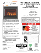
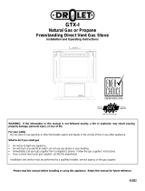
APPLIANCE DIMENSIONS
APPLIANCE DESCRIPTION
MAIN CONTROL PANEL
UPPER LOUVERS
GLASS DOOR
LOWER LOUVERS
DIMENSIONS
A HEIGHT 30” (762 mm)
B WIDTH 27” (685 mm)
C DEPTH 17 ½” (444 mm)
A
C
B

Optima 45 - 3 9
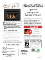
DIMENSIONS AND CLEARANCES
ALCOVE INSTALLATION
* Side and back clearances for the alcove installation is the same as the straight and the corner installations
TOP VIEW
4” (101 mm)
4” (101 mm)
4” (101 mm)
STRAIGHT INSTALLATION
CORNER INSTALLATION
11” (280 mm)
11” (280 mm)
SIDEWALL
BACKWALL
SIDE VIEW
2” (50 mm) to top, 1” (25 mm) to
bottom and side surfaces of the vent
4” (101 mm) minimum
clearance required
BACKWALL
FLOOR
24” (610 mm) minimum clearance
required from top of the appliance
to a combustible material
1” (25 mm) to the surface of the vent
NOTE: The Optima 45-3 does
not require a non-combustible
hearth pad and can be installed
directly on the floor.

Optima 45 - 3 10
LOCATING GAS HEATER
This appliance must be installed in a location that is free of plumbing, electrical wiring and
heating or air conditioning ducts. Select a location that is accessible for venting.
See ALLOWABLE TERMINATION LOCATIONS listed in this manual.
VENT TERMINATION LOCATIONS
1. See ALLOWABLE TERMINATION LOCATIONS and establish a suitable vent termination location.
2. In heavy snowfall areas make sure the vent termination is located where it can not be blocked by
snow and from snowfall or snow removal equipment.
3. Locate the vent termination away from plants, bushes or any other object near the vent termination
that will interfere or obstruct the air flow around it.
4. DO NOT recess vent termination into walls, sidings or planters.
5. Vent terminations located below 7ft (2.13 M) from grade level or anywhere that it can be a burn
hazard to the public, such as patios and balconies, must be protected with an approved termination
cage. If using Archgard Venting System order (Part # C-1).
NOTE: See venting chart for maximum and minimum vertical/horizontal venting configurations.

Optima 45 - 3 11
ALLOWABLE TERMINATION LOCATIONS
Canadian Installations (1) US Installations (2) Canadian Installations (1) US Installations (2)
A= Clearance above grade,
veranda, porch, deck, or
balcony
12 inches (30 cm) 12 inches (30 cm) J= Clearance to non-mechanical air
supply inlet to building or the
combustion air inlet o any other
appliance
12 inches (30 cm) 9 inches (23 cm)
B= Clearance to window or
door that may be opened
12 inches (30 cm) 12 inches (30 cm) K= Clearance to a mechanical
air supply inlet
6 feet (1.83 m) 3 feet (91 cm) above if
within 10 feet (3 m) hori-
zontally
C= Clearance to permanently
closed window
* * L= Clearance above paved
sidewalk or paved driveway
located on public property
7 feet (2.13 m) + *
D= Vertical clearance to
ventilated soffit located
above the terminal within a
horizontal distance of 2 feet
(61 cm) from the center line
of the terminal
* * M= Clearance under veranda,
porch, deck, or balcony
12 inches (30 cm) ++ *
E= Clearance to unventilated soffit * *
F= Clearance to outside corner * *
G= Clearance to inside corner * *
H= Clearance to each side of
center line extended above
meter/regulator assembly
3 feet (91 cm) within a
height 15 feet (4.5 m)
above the
meter/regulator assembly
*
L= Clearance to service
regulator vent outlet
3 feet (91 cm) *
(1) In accordance with the current CSA B149.1, National Gas and Propane Installation
Code
(2) In accordance with the current ANSI Z223.1/NFPA 54, National Fuel Gas Code
(+) A vent shall not terminate directly above a side walk or paved driveway that is located
between two single family dwellings and serves both dwellings
(++) Permitted only if veranda, porch, deck, or balcony is fully open on a minimum of two
sides beneath the floor.
(*) For clearances not specified in ANSI Z223.1/NFPA 54 or CSA B149.1, “Clearances shall
be in accordance with local installation codes and the requirements of the gas supplier.”

Optima 45 - 3 12
APPROVED VENT COMPONENTS
For best and safe venting performance, here are some general venting rules:
• Use only Archgard or Simpson Dura-Vent direct vent systems and components.
• Maintain a minimum of 1” (25 mm) clearance to combustibles from the outside surfaces of
vertical vents and minimum of 1” (25 mm) sides and bottom, and 2” (50 mm) from top surfaces
of horizontal vents.
• Observe local code restrictions, if any, regarding the installation of this type of gas appliance.
• Observe the venting charts given in this manual
• Use vent spacers between the inside 4” (101 mm) and outside 7” (178 mm) vents at 3 ft (915
mm) intervals (Archgard Direct Vent System ONLY).
• Never slope horizontal vents downwards, towards the vent termination.
• Maintain a minimum ¼” rise (6mm) for every linear foot (305 mm) of horizontal vent.
• Terminate (Horizontally) the vent only with an approved vent termination supplied by Archgard
Part # TK-1 or Simpson Dura-Vent Termination Cap.
• Terminate (Vertically) the vent only with Simpson Dura-Vent Vertical Termination Cap.
• Support horizontal vents every 3 ft (915 mm) to prevent sagging.
VENTING CONNECTION
The appliance will not function without being connected to a proper venting system.
This appliance may only use direct vent system supplied by Archgard, or Simpson Dura-Vent
direct vent systems with the appropriate Adaptor dependent upon the venting guidelines within
this manual.
Please, strictly follow the venting instructions for optimum performance from
the appliance, and to avoid sooting and/or service calls.
PART # DESCRIPTION
TVK-FSU Archgard Top Vent Kit. Kit includes 9 ft (2.74 M) of 4” (101 mm) gas flex
liner, 36” (914 mm) of 7” (178 mm) black stove pipe, 24” (610 mm) of
7” (914 mm) black stove pipe, 90
o
deg. black elbow, wall sleeve, firestop
and horizontal termination cap (TK-1)
TK-1 Archgard Horizontal termination head only
C-1 Archgard Safety Cage for Horizontal termination head (TK-1)
VSD-1 Archgard Vinyl siding deflector
SNK-24 Archgard Snorkel termination head only
C-2 Archgard Safety Cage for Snorkel termination head (SNK-24)
SDA-U Adapter, Appliance to Simpson Dura-Vent
DV-GS Simpson Dura-Vent venting system
NOTE: Only venting components listed below are approved for the Optima 45-3

Optima 45 - 3 13
VENTING - RESTRICTOR PLACEMENT
NOTE: Vent restrictors are designed to reduce vertical stack action for vent
terminations which will reduce the velocity of incoming combustion air and
not adversely affect the standing pilot or the efficiency of the appliance.
RESTRICTOR PLACEMENT FOR SIDEWALL VENTED APPLICATIONS ONLY
WARNING: These restrictors are only to be installed in the vent system if the vent exceeds 10’ in
vertical height. See below which restrictor to use.
Installing them under any other circumstances may cause hazardous venting
conditions and may result in personal injury, property damage or death.
NOT FOR USE IN VERTICALLY VENTED APPLICATIONS
Restrictor Number #1
Sidewall Venting - Above
Ten Feet (10’)
Restrictor Number #2
Sidewall Venting - Above
Eighteen Feet (18’)
Archgard System
Archgard System
In the Archgard system, the
restrictors are placed on the
exhaust outlet on the appliance.
Simpson Dura-Vent
Simpson Dura-Vent
With Simpson Dura-Vent,
locate the restrictor in the exhaust
section fitting into the formed lip.

Optima 45 - 3 14
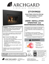
VENTING CHART
The appliance will not function without being connected to a proper venting system.
This appliance may only use direct vent system supplied by Archgard, or Simpson Dura-
Vent direct vent systems with Archgard SDK-3 adapter.
Please strictly follow the venting instructions for optimum performance
from the appliance and to avoid sooting and/or service calls.
V
E
R
T
I
C
A
L
H
E
I
G
H
T
7.93 M
7.32 M
6.71 M
6.10 M
5.49 M
4.88 M
4.27 M
3.66 M
3.05 M
2.44 M
1.83 M
1.22 M
610 mm
Note: No Installations are
permitted outside of this
range.
610
mm
1.22 1.83 2.44 3.05
3.66
Meters
• A minimum of 3’ (914 mm) of vertical vent to center of elbow is required for a maximum horizontal
run of 3’ (914 mm).
• Chart is for one 90° bend, with ¼” (7 mm) vertical raise minimum per foot of horizontal length.
• For each additional 90° or two 45°, add one foot of vertical height.
• Maximum three 90º bends, or equivalent.
• Minimum 2 ft (610 mm) straight length between bends.
Note: See instructions on page
13 for restrictor placement.
Feet
VENTING ABOVE ROOF OF THE HOUSE USING A VERTICAL TERMINATION
Use Simpson Dura-Vent listed direct vent system caps for all vertical vent termination
applications (through the roof).
No restrictors are to be used
in vertical vent installations.
Sidewall installation only
Sidewall
installation only

Optima 45 - 3 15
1. Maintain 1” (25 mm) clearance (air space) to combustibles when passing through ceilings
walls, roof, enclosures, attic rafter, or other nearby combustible surfaces. Do not pack air
spaces with insulation. Check page 14 (Venting Chart) for the maximum vertical rise of the
venting system.
2. Set the gas appliance in its desired location. Drop a plum bob down from the ceiling to the
position of the appliance flue exit, and mark the location where the vent will penetrate the
ceiling. Drill a small hole at this point. Next, drop a plumb bob from the roof to the hole pre-
viously drilled in the ceiling, and mark the spot where the vent will penetrate the roof.
NOTE: you may wish to relocate the appliance to avoid cutting load-bearing members.
3. A Firestop spacer must be installed in the floor or ceiling of every level. To install the
Firestop spacer in a flat ceiling cut a 10” (254 mm) square hole. Frame the hole as shown
Fig. 1 and install the firestop.
4. Assemble the desired lengths of pipe and elbows as outlined in the Venting Chart, neces-
sary to reach from the Appliance adaptor (SDA-U), if using Simpson Dura-Vent from the ap-
pliance up through the roof. Ensure that all Simpson Dura-Vent and/or flexible is connected
and sealed accordingly.
5. Cut a hole in the roof centered on the small drill hole placed in the roof as outlined in Step 2.
6. The hole should be of sufficient size to meet the minimum requirements for each combusti-
bles of 1” (25 mm). Slip the flashing under the shingles (shingles should overlap half of the
flashing) as per Fig.2.
7. Continue to assemble pipe lengths and/or flexible gas venting.
8. Ensure vent is vertical and secure the base of the flashing to the roof with roofing nails,
slide storm collar over the section and seal with a mastic.
9. Install the vertical termination cap by twist-locking it.
NOTE: Apply high temperature sealant to inner and outer pipe on every Simpson Dura-Vent
twist-lock joint. See Fig. 3
10” (254mm)
square hole
framing
firestop
spacer
Fig. 1 Fig. 2
Female
Locking Lugs
Male
Locking Lugs
Fig. 3
Sealant
VENTING - VERTICAL TERMINATION USING SIMPSON DURA-VENT PIPE
The Optima 45-3 can be vented vertically using Simpson Dura-Vent Direct Vent System. To
vent using Simpson Dura-Vent exclusively, you must use the Archgard SDA-U Adaptor and
connect the (SDA-U) adaptor to the top of flue outlet on the Optima 45-3 gas fireplace.

Optima 45 - 3 16
NOTE:
• Galvanized pipe is desirable above the roofline
due to its higher corrosion resistance. Continue
to add pipe sections throughout the flashing until
the height of the vent cap meets the minimum
height requirements specified in Fig. 5 or local
codes.
• For steep roof pitches, the vertical height must
be increased. A poor draft, or down drafting can
result in high wind conditions, trees or neighbor's
roof lines. In these cases increasing the height
may solve a drafting problem. REMEMBER to
check that you are within the maximum vertical
height restrictions, and are placing the appropri-
ate vent restrictors as outlined in the venting
chart within this manual.
• Any storage spaces or closets which the vent
must pass through must be enclosed.
Flat to 7/12 2 Feet 0.61 Meters
Over 7/12-8/12 2 Feet 0.61 Meters
Over 8/12-9/12 2 feet 0.61 Meters
Over 9/12-10/12 2.5 Feet 0.76 Meters
Over 10/12-11/12 3.25 Feet 1.00 Meters
Over 11/12-12/12 4 Feet 1.22 Meters
Over 12/12-14/12 5 Feet 1.52 Meters
Over 14/12-16/12 6 Feet 1.83 Meters
Over 16/12-18/12 7 Feet 2.13 Meters
Over 18/12-20/12 7.5 Feet 2.29 Meters
Over 20/12-21/12 8 Feet 2.44 Meters
Roof Pitch Minimum Vent Height
Vertical Termination
Cap
Storm Collar
Flashing
Ceiling Firestop
Round Support
Box/wall Thimble
Length of Pipe
Length of Pipe
SDA-U adaptor
VENTING - VERTICAL TERMINATION USING SIMPSON DURA-VENT PIPE
Simpson Dura-Vent venting
components are listed on page 21
Typical Vertical venting
configuration using Simpson
Dura-Vent Direct Vent System
Fig. 5
H-represents vent
height
H

Optima 45 - 3 17
NOTES: This Vent Kit must be installed directly onto the flue outlet of the heater. Maintain a
minimum of 1” (25mm) sides and bottom, and 2” (50 mm) from the top surfaces of the horizontal
vent. Use the vent spring spacers (Fig. 1) between the inner and outer vents at 3 ft (900 mm)
intervals. Maintain at least a ¼ “ (6 mm) rise for every 12” (305 mm) horizontal vent. Use the
included pipe joint compound and 3 self tapping screws at every vent connection.
1. Locate where the vent will pass though the wall, and cut and frame an 10” (25 mm) wide x
11” (279 mm) high hole.
2. Apply pipe joint compound on the 4” (101 mm) crimp end of the vent cap and slip on one end
of the flex vent. Fasten with 3 self-tapping screws.
3. Place the horizontal section of the 7” (179 mm) diameter rigid pipe over the flex vent so that
the non-crimped end fits over the corresponding crimped end on the vent cap, and screw it
in place.
4. Check the thickness of the wall and cut the 10” (25 mm) dia. x 12” (305 mm) pipe to the
thickness of the wall.
5. Place the 10” (25 mm) diameter pipe (thimble) over the other two, and screw it onto the
standoffs of the termination.
6. From the outside, pass the vents and the thimble through the hole so that the 2” (50 mm)
standoff is on the top.
7. Screw the vent cap to the wall using the 2” (50 mm) screws.
8. From the inside, place the firestop over the pipes, so that the standoffs fit into the hole and
screw it in place using the 1 ¼” (32 mm) screws. Seal with silicone sealer around pipe.
9. Similarly place the decorative trim collar over the firestop and screw it in place with
1 ¼“ (32 mm) screws.
10. Install the 1” (25 mm) diameter spring spacers, elbow, and vertical rigid pipe as shown.
11. Move the heater into place and screw the flex, then the rigid pipe onto its collars.
VENTING - HORIZONTALLY USING ARCHGARD TVK-FSU VENT KIT
NOTE:
Be sure
to include
¼” (6 mm)
rise per foot
(305 mm)
of horizontal
length.
Termination Framing
11” (279 mm)
10”
(254 mm)
Elbow
Spacer
Flex vent
Rigid pipe
Spring Spacers
Fig. 1
Insulation
Standoff
Heater
Outside wall
Flex vent
Spring spacer
Black Rigid Pipe
90° elbow
Vent cap
Collars
Wall Thimble
Firestop
Interior wall

Optima 45 - 3 18
VENTING - BELOW GRADE USING FLEXIBLE DIRECT VENT SYSTEMS
INSTALLATION PROCEDURES FOR ARCHGARD SNORKEL KIT (Part # SNK-24)
IMPORTANT: Do not locate termination head
where excessive snow or ice build up may oc-
cur. Check termination head area after every
snow fall, and clear if necessary to prevent
blockage. If using snow blowers, make sure
snow is not directed at the termination head.
1. Follow all other venting instructions in the manual regarding minimum vertical rise to hori-
zontal runs, recommended pitch, and clearances to combustible materials.
2. Locate the centerline of the termination and mark the wall. Cut an 11” x 10” (279mm x
254mm) hole in the wall. NOTE: a 2” (50mm) x 1 ½” (13mm) around the 7” (178mm) liner
is required. See Fig. 1 for termination framing.
3. Drill holes and insert the anchors as required.
4. Gently pull the coaxial vent through the hole. Apply a small bead of high temperature fur-
nace cement around the 4” (101mm) collar on the snorkel and secure the 4” (101mm) flex
vent with a stainless steel hose clamp and at least 3 screws. Make certain you have not
pulled the vent too hard and accidentally disconnected it from the appliance.
5. Securely attach the 7” (178 mm) air intake pipe to the 7” (178 mm) collar on the snorkel kit
with a 7” (178 mm) stainless steel hose clamp and three screws.
6. Apply a thick bead of all weather caulking all around the outside edges of the snorkel as-
sembly and flanges.
7. Gently feed the vent back into the opening and push the snorkel up against the wall. Line
up the holes previously drilled and lag the vent assembly to the wall.
8. Wipe off any excess caulking that squeezes out or add more to any areas that you may
suspect will allow water to seep in.
NOTE: The Archgard Snorkel kit is designed for 4” x 7” (101 mm x 178 mm) flexible gas liners
that are NOT supplied with the Snorkel Termination Head and MUST be ordered separately.
• If the Snorkel Termination is installed BELOW GRADE, (I.E. basement application) proper
drainage must be provided to prevent water from entering the Snorkel Termination.
• Do not attempt to enclose the Snorkel in the wall or any other type of enclosure.
• For Snorkel Terminations ABOVE GRADE installations follow national or local code re-
quirements.
Description Size
A Total Protrusion 13 ½” (343 mm)
B Mounting Flange 34 ½” (877 mm)
C Finished Body 33” (838 mm)
D Mounting Flange 10 ½” (267 mm)
E Finished Body 9” (228 mm)
F From Body to start of
exhaust vent
1 ¼” (31 mm)
A
B
C
D
E
F
ABOVE GRADE
Snorkel
BELOW GRADE
Snorkel
Adequate
Drainage

Optima 45 - 3 19
Measure wall thickness from the back of the fireplace standoffs to inside mounting surface of the termination cap. If
a Vinyl siding standoff is required, measure to the outside surface of the wall without siding and add 2” (50 mm).
NOTE: The Termination cap must NOT be recessed into siding. Measure wall thickness including finishing straps.
VENTING - HORIZONTALLY USING SIMPSON DURA-VENT DIRECT VENT SYSTEMS
The Optima 45-3 can be vented horizontally using Simpson Dura-Vent Direct Vent System. To vent using Simpson
Dura-Vent exclusively, you must use the Archgard SDA-U Adaptor and connect the SDA-U adaptor to the top of the
Optima 45-3 as shown in Fig. 1.
NOTE: Apply high temperature sealant to the SDA-U adaptor and the flue connection on the Optima 45-3. Seal all
pipe joints and follow all venting instructions within this manual.
NOTE: Call your local Authorized Archgard Dealer to purchase Simpson Dura-Vent Direct Vent Kits and/or venting
components.
Wall Thickness (inches) Vent Length Required (inches) Wall Thickness (mm) Vent Length Required (mm)
4” - 5 ½” 6” 101 mm - 140 mm 152 mm
7” - 8 ½” 9” 178 mm - 216 mm 228 mm
10” - 11 ½” 12” 254 mm - 292 mm 305 mm
9” - 14 ½” 11” - 14 ⅝” Adj. Pipe 228 mm - 368 mm 228 mm - 371 mm
15” - 23 ½” 17” - 24” Adj. Pipe 381 mm - 597 mm 432 mm - 610 mm
Flat Wall Installation
Wall Thickness (inches) Vent Length Required (inches) Wall Thickness (mm) Vent Length Required (mm)
3 ¼” - 6 ¾” 11” - 14 ⅝” Adj. Pipe 82 mm - 171 mm 228 mm - 371 mm
7 ¾” - 16 ¼” 17” - 24” Adj. Pipe. 197 mm - 412 mm 432 mm - 610 mm
7 ¼” - 8 ¾” 6” + 12”
Or 9” + 9”
184 mm - 222 mm 101 mm + 305 mm
Or 228 mm + 228 mm
4 ¼” - 5 ¾” 6” + 9” 108 mm - 146 mm 152 mm - 228 mm
Corner Installations
Minimum components required for horizontal termination using Simpson Dura-Vent:
1 SDA-U (Appliance adaptor) 1 90 Deg. Elbow
1 Horizontal Termination Cap 1 Wall Thimble
1 Length of pipe for top of appliance 1 Length of pipe to suit wall thickness
Part # Description
971 Horiz. Term. Kit Includes; 90
0
. Blk elbow, wall thimble
cover, Horiz. square term. Cap, 24” (610 mm) blk pipe
and 11”-14” (279 mm x 356 mm) adj. blk pipe.
970 Basic Horiz. Term. Kit Includes; 90
0
. blk elbow, wall
thimble cover, Horiz. square term. cap.
987 Vertical Termination Kit Includes;
0/12- 6/12 pitch adj. flashing, storm collar, low profile
term. cap.
908B 6” (152 mm) Pipe Length - Black
907B 9” (228 mm) Pipe Length - Black
906 12” (305 mm) Pipe Length - Galv.
906B 12” (305 mm) Pipe Length - Black
904 24” (610 mm) Pipe Length - Galv.
904B 24” (610 mm) Pipe Length - Black
903 36” (914 mm) Pipe Length - Galv.
903B 36” (914 mm) Pipe Length - Black
Part # Description
902 48” (1.22 M) Pipe Length - Galv.
902B 48” (1.22 M) Pipe Length - Black
911B 11” - 14 ⅝” (228 mm x 371 mm) Adj. Pipe
Length - Black
917B 17”’ - 24” (432 mm) x (610mm) Adj. Pipe
Length - Black
945 45
0
Elbow - Galv.
945B 45
0
Elbow - Black
945G 45
0
Elbow - Swivel - Galv.
945BG 45
0
Elbow - Swivel - Black
990 90
0
Elbow - Galv.
990B 90
0
Elbow - Black
990G 90
0
Elbow - Swivel - Galv.
990BG 90
0
Elbow - Swivel - Black
991 Vertical Termination Cap High Wind
980 Vertical Termination Cap
Part # Description
984 Horizontal (Square) Termination Cap
985 Horiz. (SQ) Term. Cap. High Wind.
982 Snorkel - 14” (356 mm) Rise Term. Cap
981 Snorkel - 36” (914 mm) Rise Term. Cap
940 Wall Thimble - Support Box
941 Cathedral/Ceiling - Support Box
3951 Brass Trim for Wall Thimble/Ceiling Sup.
963 Firestop Spacer
943 Flashing 0/12 - 6/12
943S Flashing 7/12 - 12/12
953 Storm Collar
950 Vinyl Siding Standoff
988 Wall Strap
942 Wall Thimble
SIMPSON DURA-VENT DIRECT VENT PARTS LIST 6 ⅝” x 4” (168 mm x 101 mm)
See your Authorized Archgard Dealer for price and availability.

Optima 45 - 3 20
VENTING - HORIZONTALLY USING SIMPSON DURA-VENT DIRECT VENT SYSTEMS
1. Set the Optima 45-3 in its desired location.
Determine if wall studs or roof rafters are in
the way the when venting system is at-
tached. You may want to adjust the location
of the unit to compensate.
2. Simpson Dura-Vent Venting System is de-
signed with special twist-lock connections to
connect to the appliance. An Archgard adap-
tor (SDA-U) is required. The adaptor will al-
low Simpson Dura-Vent System to be used.
3. Apply a bead of silicone inside the outer sec-
tion of the SDA-U adaptor (crimped side).
Slip the adaptor over the existing inner and
outer flue collar and fasten it to the outer col-
lar only with 3 screws (drill pilot holes first).
Level the appliance and fasten it to the fram-
ing using nails or screws through the nailing
strips.
4. Assemble the desired combination of pipe
and elbows to the appliance adaptor and
twist lock the pipe.
NOTE: Twist-lock procedure: Four indenta-
tions, located on the female ends of the pipes
and fittings, are designed to slide straight onto
the male ends of adjacent pipes and fittings by
orientating the four pipe indentations so they
match and slide in to the four entry slots on the
male ends (Fig. 2). Push the pipe sections
completely together, then twist-lock one sec-
tion clockwise approximately one quarter turn,
until the two sections are fully locked. The fe-
male locking lugs will not be visible from the
outside, on the pipe or fittings. They may be
located by examining the inside of the female
ends. Horizontal vent runs MUST be supported
every three feet (76 mm). Wall straps are avail-
able for this purpose.
INSTALLATION PROCEDURES FOR SIMPSON DURA-VENT DIRECT VENT SYSTEM
Female
Locking
Lugs
Sealant
Male
Locking
Lugs
Fig. 2
#1
#2
#3
#4
#5
#6
#7
#8
Fig. 1
#1 Vertical Termination
#2 Vinyl Siding Standoff
(Optional)
#3 Wall Thimble
#4 Round Support Box
#5 Adj. Length of pipe
#6 90
0
Elbow
#7 Pipe Length
#8 SDA-U Adaptor 3” (76mm)
Refer to Venting Chart on Page 16
Page is loading ...
Page is loading ...
Page is loading ...
Page is loading ...
Page is loading ...
Page is loading ...
Page is loading ...
Page is loading ...
Page is loading ...
Page is loading ...
Page is loading ...
Page is loading ...
Page is loading ...
Page is loading ...
Page is loading ...
Page is loading ...
Page is loading ...
Page is loading ...
Page is loading ...
Page is loading ...
Page is loading ...
Page is loading ...
Page is loading ...
Page is loading ...
Page is loading ...
Page is loading ...
Page is loading ...
Page is loading ...
Page is loading ...
/