Page is loading ...

200-0191-14
October 11, 2023
− Do not store or use gasoline or other flammable
vapors and liquids in the vicinity of this or any other
appliance.
WHAT TO DO IF YOU SMELL GAS:
• Do not try to light any appliance.
• Do not touch any electrical switch; do not use any
phone in your building.
• Leave the building immediately.
• Immediately call your gas supplier from a neighbor’s
phone. Follow the gas supplier’s instructions.
• If you cannot reach your gas supplier, call the fire
department.
− Installation and service must be performed by a
qualified installer, service agency or the gas supplier.
WARNING:
FIRE OR EXPLOSION HAZARD
Failure to follow safety warnings exactly could result in
serious injury, death, or property damage.
INSTALLATION, OPERATION,
AND MAINTENANCE MANUAL
Optima 34
Model: 34-DVI34N-2
Direct Vent Fireplace Insert
Serial Numbers 44918 and higher
This appliance may be installed in an aftermarket
permanently located, manufactured home (USA only) or
mobile home where not prohibited by local codes.
This appliance is only for use with the type of gas indicated on
the rating plate. This appliance is not convertible for use with
other gases, unless a certified kit is used.
Archgard Fireplace Products
7116 Beatty Dr
Mission, BC V2V 6B4
Canada
Gas Fireplace
Efficiency Rating
52.23%
Based on CSA P.4.1-15
INSTALLER:
LEAVE THIS MANUAL WITH THE
APPLIANCE.
CONSUMER:
RETAIN THIS MANUAL FOR FUTURE
REFERENCE.
For use with natural gas or propane
(Conversion kit required for Propane use)

TABLE OF CONTENTS
Caution and Safety Instructions 5
Appliance Certification, Installation Codes and Specifications 6
Appliance Dimensions and Minimum Requirements for Fireplace Dimensions 8
Clearance to Combustibles 9
Gas Connections 11
Appliance Description, Leveling the Appliance and Electrical Requirements 12
Venting Instructions 13 - 15
Surround Installation and Rocker Switch Wiring 16
Optional Wall Switch, Thermostat or Remote Control. Suggested wiring. 17
Brick and Log Placement 18 - 25
Final Installation Check and Initial Operation 26
First Fire and Lighting Instructions (CAUTION) 27
Lighting Instructions on Rating Plate 28
Glass Door Removal / If Your Glass Should Break
Safety Screen Barrier Installation
29
Troubleshooting Guide 31 - 32
Maintenance and Cleaning the Appliance 33
Servicing Under Warranty and Adjusting Primary Air 34
Adjusting Primary Air (Continued) and Changing Main Burner Orifice 35
Checking Inlet/Outlet gas pressures, Adjusting Pilot and Convertible Pilot Orifice 36
Replacing Convection Blower & Wiring Diagram 37
Valve Tray Assembly and Parts List 38
Fiber Logs & Pan Burner Assembly and Parts List 39
Replacement Parts List - General Parts 40 - 41
Warranty 42
Frequently Asked Questions 43
Warranty Registration Card 47
30

INTRODUCTION
Congratulations on choosing an Archgard Gas Fireplace!
The 34-DVI34N-2 Direct Vent Insert is one of the most advanced Direct Vent Insert heaters
available today. It is solidly designed using the latest technology and manufactured to the
highest quality. It is our aim to provide you with an appliance for many trouble-free years of
reliable service.
Some of the many features of your 34-DVI34N-2 Direct Vent Insert are:
• Heater Classification: The 34-DVI34N-2 is classified as a heating appliance. Therefore,
it uses Direct Vent safety technology and it is suitable for continuously operated zone
heating.
• High Efficiency: The 34-DVI34N-2 has one of the highest efficiencies of any Direct Vent
gas insert, which means that it is less expensive to operate.
• Adjustable Fan Speed: Each 34-DVI34N-2 insert comes complete with a heat-activated
circulation fan with a fully adjustable speed control.
• Adjustable Flame: The flame aesthetics and heat output can be adjusted to suit the
owner’s liking and heating needs.
• Solid Construction: The 34-DVI34N-2 is mainly constructed of 16 and 18 gauge
galvanized and aluminized coated steel for long life and durability.
• Optional Accessories: Check with your Authorized Archgard Dealer for a full
complement of decorative accessories to suit your home’s décor and your tastes. Some
of the accessories available are: 24K Gold Overlay (for the flat window), a variety of
surrounds (faceplates) with gold, black or pewter trims and an overlay bay window that
simply attaches to the front of your fireplace while leaving the flat glass door in place.
• Millivolt Control System: The 34-DVI34N-2 uses a gas control valve that is ready for an
optional wall thermostat, or a hand-held wireless remote control.
Fireplace Serial Number
Date of Installation
Type of Gas Used by the Fireplace
Dealer’s Name
Please complete and submit the warranty registration card included in the back of this manual or by
visiting us at: www.archgard.com/warranty-registration
Model Number Definition (34-DVI34N-2)
34 Number assigned to identify the fireplace
DVI Direct Vent Insert
34 Natural Gas Input Rating in BTU
N Natural Gas / Traditional Log Burner
-2 Revision Number

34-DVI34N-2 4
Safety Informaon
Cauon
FOR YOUR SAFETY - Do not install or operate your 34-DVI34N-2 without reading and understanding this manual.
Any installation or operational deviation from this instruction manual voids the warranty and may prove hazardous.
• This appliance must be installed by a qualified gas installer and the installation must conform to the installation
codes
• Provide adequate clearance around air openings into combustion chamber
• Never obstruct front openings
• Provide adequate clearances for proper operation and servicing of the appliance
• This appliance must be properly connected to an approved venting system and must not be connected to a chim-
ney flue serving a separate solid fuel burning appliance
• Flow of combustion and ventilation air must not be obstructed - always provide adequate combustion and
• ventilation air
• Always provide adequate clearance around the intake and exhaust openings
Safety
• Due to high temperatures, the appliance should be located out of traffic and away from furniture and draperies
• Children and adults should be alerted to the hazards of high surface temperature and stay away to avoid burns or
clothing ignition
• If this appliance is installed directly on carpeting, tile, or other combustible material other than wood flooring, the
appliance shall be installed on a metal or wood panel extending the full width and depth of the appliance
• Young children should be carefully supervised when they are in the same room as the appliance. Toddlers, young
children and others may be susceptible to accidental contact burns. A physical barrier is recommended if there
are at risk individuals in the house. To restrict access to a fireplace or stove, install an adjustable safety gate to
keep toddlers, young children and other at risk individuals out of the room and away from hot surfaces
• Do not store or place combustibles, gasoline, and other flammable vapors and liquids near the appliance
• Clothing or other flammable material should not be placed on or near the appliance
• WARNING: Do not operate appliance with the glass front removed, cracked, or broken. Removal of the glass
should be done by a licensed or qualified service person. Do not to strike or slam the glass
• Any safety screen or guard removed for servicing an appliance must be replaced prior to operating
• Installation and Repair should be done by a qualified service person. The appliance should be inspected before
use and at least annually by a professional service person. More frequent cleaning may be required due to
excessive lint from carpeting, bedding materials, etc. It is imperative that the control compartments, burners and cir-
culating air passageways of the appliance are kept clean
• Under no circumstances should any solid fuel (wood, coal, paper or cardboard, etc.) be used in this appliance
• Keep burner and control compartment clean
• Do not use this appliance if any part has been under water. Immediately call a qualified service technician to in-
spect the appliance and to replace any part of the control system and any gas control which has been under wa-
ter
• California Proposition 65 Warning: This product can expose you to chemicals including Carbon Monoxide,
that is an externally vented by-product of fuel combustion, which is [are] known to the State of California to
cause cancer, birth defects, or other reproductive harm. For more information, visit www.P65Warnings.ca.gov.
Each Archgard Gas Fireplace is checked and tested at the factory prior to being packaged and shipped to our dealers
and finally installed in your home. Before leaving this unit with the customer, the installer must ensure that the appli-
ance is firing correctly and that the electrical system is in working order. The Installation Checklist should be used to
ensure the proper installation of this gas fireplace heater and to document any deviations from a typical install.
Any alteraon to the product that causes carbon or soot deposits that results in any damage or requires cleaning is not the
responsibility of the manufacturer.

34-DVI34N-2 5
This appliance is tested and certified to the following USA and Canadian gas appliance standards.
- ANSI Z21.88-2019 / CSA 2.33-2019 Vented Gas Fireplace Heaters
- CAN / CGA 2.17 – M91 (R2009) Gas Fired Appliances for use at High Altitudes
- CSA – P.4.1-15 – Testing Method for Measuring Annual Fireplace Efficiency
- CSA C22.2 No.3 – M1988(R.2014) – Electrical Features of Fuel-Burning Equipment
The listing label is attached to the appliance on the bottom left side of the appliance. A copy is shown on the
following page.
Commonwealth of Massachusetts: This appliance has been manufactured in accordance with
Massachusetts code 248 CMR 5.00. Approval Code: G1-0319-387 . (https://licensing.reg.state.ma.us/pubLic/
pl_products/pb_pre_form.asp).
Please contact Archgard Industries Ltd., if you have any questions regarding the certification of this appliance.
APPLIANCE CERTIFICATION
INSTALLATION CODES
This appliance must be installed by a qualified gas appliance installer. The installation must conform
with the local codes or, in the absence of local codes, with the current National Fuel Gas Code ANSI
Z223.1/ NFPA 54. Electrical connections and grounding must conform with local code, or current
National Electrical code ANSI/NFPA No. 70-1987.
We recommend that our gas hearth products be installed and serviced by professionals who are
certified in the U.S. by the National Fireplace Institute®(NFI) as NFI Gas Specialists.
SPECIFICATIONS
Natural Gas (NG) Propane (LP)
Manifold Pressure 1.6-3.5 in. W.C. (0.4-0.9 kPa) 6.4-10.0 in. W.C. (1.6-2.5 kPa)
Min. Supply Pressure
Max Supply Pressure
5.0 in. W.C. (1.2 kPa)
14.0 in. W.C. (3.5 kPa) 11.0 in. W.C. (2.7 kPa)
14.0 in. W.C. (3.5 kPa)
Orifice Size #34 DMS (2.8 mm dia) #51 DMS (1.72 mm dia)
Nominal Input Rating 23,000 - 34,000 BTU/hr (6.6- 9.8kW) 26,000 - 34,000 BTU/hr (7.5 -9.8kW)
P.4 Fireplace Efficiency (FE) 52.23% 52.23%
P.4 Steady State Efficiency 65.20% 65.20%
Electrical Rating 120 VAC, 60Hz less than 2 A. 120 VAC, 60Hz less than 2 A.
Gas Control ROBERTSHAW 7000 MVRB ROBERTSHAW 7000 MVRB
Altitude 0 - 4,500 ft. (0 - 1372 M) 0 - 4,500 ft. (0 - 1372 M)
Primary Air Opening ¼” (6 mm) OPEN FULLY OPEN
HIGH ALTITUDE INSTALLATION
When installing this appliance beyond 4500 ft. (1372 M) above sea level, the appliance must be properly de-
rated and installed according to local codes, in the absence of local codes, with the current National Fuel Gas
Code, ANSI Z223.1/ NFPA 54.

34-DVI34N-2 6
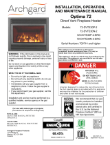
RATING PLATE SAMPLE

34-DVI34N-2 7
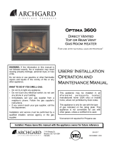
MINIMUM FIREPLACE DIMENSIONS
J
SIDE
VIEW
TOP VIEW
L
M
K
APPLIANCE DIMENSIONS
DIMENSIONS
A 25-5/8” (651 mm) G 19-7/8” (505 mm)
B 16” (406 mm) H 3-3/4” (93 mm)
C 14” (356 mm) I 1-1/4” (32 mm)
D 14-1/8” (359 mm)
DSK-32 or ESK-32
(STANDARD SURROUND)
E 41-1/2” (1054 mm)
F 27-3/4” (705 mm)
LSK-32
(LARGE FLAT SURROUND)
E 47-1/2” (1207 mm)
F 30-3/4” (7457 mm)
DIMENSIONS
J 20” (508 mm)
K 15-3/4” (400 mm)
L 16-1/2” (419 mm)
M 27” (685 mm)
WARNING: Failure to position the parts in accordance with these diagrams or failure to use only parts
specifically approved with this appliance may result in property damage or personal injury.
The installer must mechanically attach the marking supplied with the gas fireplace insert to the inside of the firebox of
the fireplace into which the gas fireplace insert is installed.
Cutting of any sheet-metal parts of the fireplace, in which the gas fireplace insert is to be installed, is prohibited.
If the factory-built fireplace has no gas access hole (s) provided, an access hole of 1 1/2” (37.5 mm) or less may be
drilled through the lower sides or bottom of the firebox in a proper workmanship-like manner. This access hole must
be plugged with non-combustible insulation after the gas supply line has been installed.
The fireplace flue damper can be fully blocked open or removed for installation of the gas fireplace insert.
The fireplace and fireplace chimney must be clean and in good working order and constructed of non-combustible
materials. The chimney cleanouts must fit properly.
Refractory, glass doors, screen rails, screen mesh and log grates can be removed from the fireplace before installing
the gas fireplace insert.
Smoke shelves and baffles may be removed if attached by mechanical fasteners. Trim panels must not seal ventila-
tion openings in the fireplace.
Min flue size required 4” (102) x 7” (178)
Multi-sided Fireplaces:
This fireplace insert may be inserted in a multi-sided masonry fireplace.
The sides not filled with the insert and surround may be covered or closed off using any non-combustible material.
Do not use combustible materials. Do not block ventilation openings.

34-DVI34N-2 8
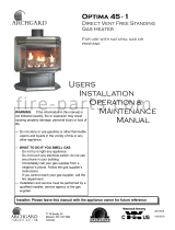
CLEARANCES TO COMBUSTIBLES
TOP VIEW
SIDE VIEW
Clearances to Faceplate
1” (25 mm) 1” (25 mm)
Sidewalls or Mantle Supports
CAUTION: This appliance is designed for use in any masonry or factory-built, wood-burning
fireplace. It cannot be enclosed by combustible material and used as a built-in gas fireplace.
WARNING: Failure to position the parts in accordance with these diagrams or failure to use
only parts specifically approved with this appliance may result in property damage or personal
injury or loss of life.
Combustible mantle allowed in
shaded area. Mantle extension
maybe increased 1” (25 mm) for
each additional 1” (25 mm)
increase in clearance height.
Example: If using a 5” (127 mm)
reduce minimum height to
36” (914 mm).
If using a 4” (100 mm) reduce
minimum height to 35” (889 mm)
Note: With bay window
attached clearances
remain the same.
6” (152 mm)
Minimum Height
From Bottom of
Appliance: 37”
(940 mm) with a
6” (152 mm) mantel.
Minimum 1” (25 mm)
clearance is required from the
faceplate (fireplace surround)
to a sidewall or mantle
support. See APPLIANCE
DIMENSIONS for surround
sizes.
sided masonry
The sides not filled with the insert
and surround may be covered or
combustible material. Do not use

34-DVI34N-2 9
3”
(76.2 mm)
16”
(406 mm)
HEARTH CLEARANCES
WARNING: Failure to position the parts in accordance with these diagrams or failure to use
only parts specifically approved with this appliance may result in property damage or personal
injury or loss of life.
Any Hearth that extends outward in front of the insert must not have any combustible material
closer than 3” (76.2 mm) to the bottom of the gas fireplace insert regardless of whether a
noncombustible material covers the combustible material. This includes any type of framing
underneath a noncombustible material such as tile, marble, or stone. Any material farther than
3” (76.2 mm) to the bottom or 16” (406 mm) from the front of the door of the gas fireplace may
be combustible.
Non Combustible
Zone
28.5” (723.9 mm)
16”
(406 mm)
NOTE: All specified clearances must be maintained from the top surface of carpeting, tile, etc.

34-DVI34N-2 10
Before connecting the appliance to the gas supply line, double check that the appliance you
have purchased is designed for the gas type you are using. The gas type markings are located
on the certification label and also on the appliance’s gas valve.
Adequate clearance for proper installation and checking of the gas connections must be
provided. All gas connections must be checked for gas leaks.
GAS CONNECTIONS
Have your gas supplier or a qualified gas fitter run a gas supply line into the fireplace. The line
must be properly sized and fitted according to the installation codes. Immediately upstream of the
supply connection, the fitter shall provide an accessible manual shut-off valve and a 1/8” (3 mm)
NPT plugged tapping accessible for connection to a test gauge. When connecting the supply line
to the gas valve, the installer shall brace the gas valve to ensure that the gas valve is not moved
from its bracket. If the valve is not braced when the supply line is connected, the valve may be
moved and cause a “break” in the main burner supply line. Such damage is not covered by the
manufacturer’s warranty.
CAUTION: The appliance and its individual shutoff valve must be disconnected from the gas
supply piping system during any pressure-testing of that system at test pressures in excess of 1/2
psig (3.5 kPa). The appliance must be isolated from the gas supply piping system by closing its
individual manual shutoff valve during any pressure-testing of the gas supply piping system at
test pressures equal to or less than 1/2 psig (3.5 kPa). Failure to do so will damage the
appliance’s gas valve. Such damage is not covered by the manufacturer’s warranty.
Natural Gas Pressure Settings:
The inlet supply or line pressure must be a minimum of 5.0” W.C. (1.2 kPa) and a maximum of
14.0” W.C. (3.5 kPa). The orifice is a #34 DMS (2.79 mm) drill size.
ELEVATION INPUT RATING
0-4500 ft (0-1372 M) 34,000 BTU/hr (9.8 kW)
4500 ft (1372 M) and above. 34,000 BTU/hr (9.8 kW) less 4% per 1000 ft. (305 M)
Please contact your local distributor for the appropriate orifice size you require.
Propane Pressure Settings:
The inlet supply or line pressure must be a minimum of 11” W.C. (2.8 kPa) and a maximum of
14.0” W.C. (3.5 kPa). The orifice is a #51 DMS (1.72 mm) drill size.
ELEVATION INPUT RATING
0-4500 ft. (0-1372 M) 34,000 BTU/hr (9.8 kW)
4500 ft. (1372 M) and above. 34,000 BTU/hr (9.8 kW) less 4% per 1000 ft. (305 M)
Please contact your local distributor for the appropriate orifice size you require.
NOTE: THE INPUT RATING SHOULD ALWAYS BE CHECKED WHEN FIRST RUNNING THIS
APPLIANCE. To do this, reduce the background flow rate, time the meter, light the fireplace and
take another reading after 15 minutes of operation. Check with your gas supplier for the gas BTU
content at your elevation. Input is the rate of flow multiplied by the heating value of the gas (cubic
feet/hour x BTU per cubic feet). Adjust the manifold pressure so that the unit does not operate
above the rated input.

34-DVI34N-2 11
LEVELING THE 34DVI34N-2 DIRECT VENT INSERT
Before placing the appliance into the fireplace, check the hearth of the fireplace to see if it is
level with the front of the fireplace. If it is not, measure the depth of the hearth. Loosen the
three screws of the leveling “L” bracket at the back of the appliance. Lower it to the
measurement obtained and tighten the screws.
APPLIANCE DESCRIPTION
ELECTRICAL CONNECTIONS
The 34-DVI34N-2 comes complete with a temperature-activated fan and rheostat installed and
wired to a three-prong (grounding) plug for your protection against shock hazard and should be
plugged in directly into a properly grounded three-prong receptacle. Do not cut or remove the
grounding prong from this plug.
NOTE: This appliance, when installed, must be electrically grounded in accordance with local
codes or, in the absence of local codes, with the National Electrical Code, ANSI / NFPA 70.
FRONT VIEW
Bottom
“grill” louver
Ceramic
Glass with
standard
door frame
Top “grill”
louver
Surround
“Faceplate”
Ceramic Brick
“panel” liner
TOP VIEW
On/Off
Rocker
Switch
Gas Inlet side
and power cord
outlet
Exhaust Fresh Air Intake

34-DVI34N-2 12
The 34-DVI34N-2
requires two flexible
gas flue liners:
Flue Collar (inlet) -
3” (76 mm) diameter
Flue Collar (outlet) -
3” (76 mm) diameter
Caution: Only two 3” (76 mm) “FLEX-MASTER” Model GA gas flex vent liners (or approved equivalent)
and a vent terminal is approved for use with this appliance.
Approved vent terminals are:
Archgard terminal. Part # 999-INS-TK
Simpsons Dura-Vent terminal. Part # 980, 923GK (adaptor with flashing) or 991 (high wind cap)
NO OTHER VENTING SYSTEM OR COMPONENTS MAY BE USED. If you are using “Dura-Vent” verti-
cal termination cap, follow the instructions provided with the “Dura-Vent” cap.
This appliance is designed to attach to two 3” (76 mm) co-linear aluminum flex gas liners running the full
length of the chimney. The flue length must be a minimum of 8’ (2.44 M) and a maximum of 35’ (10.6 M)
(The exhaust vent restrictor provided with this appliance must only be used by installing it in the
exhaust collar, before attaching the flex liner, on Natural gas units with vent heights to 20’ (6.1 M)
restrictor #1 20’ and above restrictor #2). Also refer to the following page for details. The minimum flue
size is 4” x7” (100 mm X 178 mm).
Masonry chimneys may take various contours which the flexible liner will accommodate, however, keep
the flexible liner as straight as possible, avoiding unnecessary bending but at all times keep a minimum of
3” (76 mm) inside bend radius.
The Air Intake Flex Liner must be connected to the inlet air collars of the termination cap and the appli-
ance. The Exhaust Flex Liner must be connected to the exhaust collars of the termination cap and the
appliance. (DO NOT MIX-UP THESE CONNECTIONS).
The Air intake and Exhaust connections are marked on the gas appliance. See Fig. 1.
CAUTION: To ensure that the venting path is not accidentally obstructed or punctured, the damp-
er of the host fireplace must be permanently disabled by either complete removal of the damper,
or welding it in its “open” position. Temporarily disabling the damper with braces, wedges, brack-
ets, etc., is not allowed.
VENTING INSTRUCTIONS
WARNING: Operation of this heater when not connected to a properly installed and main-
tained venting system can result in carbon monoxide (CO) poisoning and possible death.
The appliance must not be connected to a chimney flue serving a separate solid fuel
burning appliance.
Fresh Air Intake Exhaust
The 34-DVI34N-2 showing the Exhaust and Fresh Air Intake locations.
These connections are labeled for you.
Fig. 1
CAUTION
To ensure that the venting is not accidentally obstructed or punctured, the damper of
the host fireplace must be permanently disabled by either complete removal of the
damper, or by being fully blocked open, for the installation of a gas fireplace insert.

34-DVI34N-2 13
Install the termination cap making sure to provide sufficient space (around and on top) so you do not im-
pede the flow of air, both into and out of, the cap. This cap is only to be used for non-combustible installa-
tions. Do not recess into the top of the chimney.
1. Mark each end of one flex liner with “Air Intake”.
2. Mark each end of the second flex liner with “Exhaust”.
3. Pull the liner through the chimney.
4. Install the flashing.
5. Seal and attach the flex liner marked “Air Intake” to the vent terminal pipe marked “Air Intake” with the collar
clamp and stove cement provided with the kit. DO NOT USE SILICONE.
6. Seal and attach the flex liner marked “Exhaust” to the vent terminal pipe marked “Exhaust” with the collar
clamp and stove cement provided with the kit. DO NOT USE SILICONE.
7. Seal and attach the end of the flex liner marked “Air Intake” to the collar marked “Air Intake” on the appliance
with the collar clamp provided with the appliance and stove cement provided with the kit. DO NOT USE
SILICONE.
8. Install exhaust vent restrictors provided with the unit on Natural Gas appliances only. For vent heights
between 14’ (4.25 Meters) and 20’ (6.1 Meters) use restrictor #1, for vent height installations over 20’ (6.1
Meters) use restrictor #2. Seal and attach the end of the flex liner marked “Exhaust” to the collar marked
“Exhaust” on the appliance with the collar clamp provided with the appliance and stove cement provided with
the kit. DO NOT USE SILICONE. Use of silicone voids the warranty of the pilot assembly.
10. Attach the termination head to the termination body using the stove cement and screws provided with the kit.
NOTE: The flex liners must form a complete connection from the appliance flue collars to the vertical termination
cap.
VENTING INSTRUCTIONS 999-INS-TK
The minimum flue (chimney) size required to run the two 3” (76 mm) is 4” x7” (100 mm X 178 mm)
Front view of
DV Insert
Air Intake
Collar
Exhaust
Exhaust
Collar
3” (76 mm)
Flex Liner
Fresh Air
Intake
Min. vent height 8’ (2.44 M)
Max. vent height 35’ (10.6 M)
Vertical Termination cap
Part # 999-INS-TK
Place Vent Restrictor
in the position shown
(on the exhaust collar
before attaching the
Flex Liner) ONLY
when operating with
NATURAL GAS with a
VENT OF 14’ to
20’ (6.1 m) restrictor
#1 AND 20’ (6.1 m)
ABOVE restrictor #2
Note Vent restrictor # 1 is the
item with the notch (restrictor #
2 shown in picture

34-DVI34N-2 14
The gas fireplace can be converted from co-linear to coaxial when it is desired to remove a section of the masonry
fireplace chimney to below the roof line.
Using a Co-linear to Coaxial Adapter
WARNING
This appliance must be installed by a qualified gas appliance installer. The installation must conform with the local
codes or, in the absence of local codes, with the current National Fuel Gas Code ANSI Z223.1/ NFPA 54. Electrical
connections and grounding must conform with local code, or current National Electrical code ANSI/NFPA No. 70-1987.
The sections of coaxial pipe
cannot be longer than
6ft. or 50% of the total
vent length, whichever
is shorter
A sealed flashing must be
placed on top of the
chimney where the co-
linear to coaxial adapter
is seated
The total vent run must be a
minimum of 10ft. from
the top of the gas fire-
place insert
A 1" clearance must be
maintained from the
coaxial pipe to insula-
tion and combustible
material
The termination must be 18"
from the roof to the bottom of
the termination
Fresh air
intake Exhaust

34-DVI34N-2 15
SURROUND INSTALLATION
Make sure the gas and electrical lines are properly connected to the appliance. Slide the unit
into the fireplace and slide the excess flue liner material back onto the chimney. Before the ap-
pliance is fully recessed into the fireplace, attach the surround onto the appliance. The return
flange on the side of the surround fits on the inside of the mounting rails on the appliance.
Attach the surround to the appliance at the locations shown with the four (4) screws provided.
Then finish with the wiring connection to the on/off switch on the side of the trim. Now fully
“seat” the unit into its final position.
SCREW
LOCATIONS
CAUTION: Only Trim kit (s)
supplied by the manufacturer
should be used in the installa-
tion of this appliance.
1. Using the trim clips provided, join the left side trim (which has a notch cut for rocker switch)
to the top trim as shown in (Fig.1). Repeat with the right side trim.
2. Peel the backing from the sticky tape, then slip the assembled trim over the surround.
3. Locate the rocker (on/off) switch (with the ON side up) and push it in the notch located on the
left side.
4. Remove the coiled wires from the left side of the firebox and connect it to the rocker switch
tabs.
5. The switch wires have crimped connections that are factory installed. Simply connect the
crimped connections to the on/off (rocker) switch located on the surround.
TRIM INSTRUCTIONS FOR THE SKCAB & SKLB SURROUNDS
Fig. 2
Fresh Air Intake
On/Off
Rocker
Switch
Exhaust
Gas Inlet side
and power cord
outlet
Fig. 1

34-DVI34N-2 16
If a wall-mounted switch or a wall-mounted thermostat is desired, Archgard recommends that
the device be wired as shown in Fig 1. This will allow the original on/off rocker switch to be
used in case the device that is mounted to the wall becomes inoperable.
Note: Archgard Industries Ltd. does not manufacture or sell any wall switch or wall thermostat,
and will not extend warranty to them.
OPTIONAL WALL SWITCH OR THERMOSTAT
Thermostat / wall switch wire table
Recommended Maximum Lead Length
for two wires.
Wire Size Max. Length
14 GA. 50 Ft. (15.24 M)
16 GA. 32 Ft. (9.75 M)
18 GA. 20 Ft. (6.9 M)
20 GA. 12 Ft. (3.65 M)
22 GA. 9 Ft. (2.74 M)
VALVE CONNECTION FOR MILLIVOLT VALVE
OPTIONAL
REMOTE SWITCH
OR
THERMOSTAT
ON / OFF SWITCH
WIRE TO PIEZO
(SPARKER)
B
A
C
D
SUPPLY TUBE
THERMOCOUPLE LEAD
A ELECTRODE
B THERMOPILE
C PILOT CAP
D THERMOCOUPLE
PILOT ASSEMBLY
TP
THTP
TH

34-DVI34N-2 17
WARNING: Failure to position the parts in accordance with these diagrams or failure to use on-
ly parts specifically approved with this appliance may result in property damage or
personal injury.
Rear Brick Panel Placement as Shown
NOTE: Installing the panels in any other position other than shown will result in flame im-
pingement causing sooting of the logs, brick liner and ceramic glass viewing area.
BRICK PLACEMENT
The Archgard brick and reflective glass panels offer a variety of looks to customize your fire-
place and are purchased separately. Care must be given when first installing the bricks, and if
removed for servicing, as they can be damaged or broken if not handled properly.
After opening the brick or reflective glass panels set package, inspect to ensure that no damage
has occurred inside the package. Please report any damage immediately to your Authorized
Archgard Dealer.
Gas and vent connections must be made before installing the brick and reflective panels.
NOTE: Improper placement of panels may cause sooting on the internal parts and glass, and
will not be covered under warranty. Do not use broken or damaged logs.
The fireplace has panel mounting brackets already in place. Remove the brackets before in-
stalling the panels. Locate the brick or reflective panels and place them in the firebox as
shown. Refer to the pictured instructions on the following pages that will show how to place the
panels.

34-DVI34N-2 18
Right Brick Panel Placement as Shown

34-DVI34N-2 19
Left Brick Panel Placement as Shown
NOTE: Installing the panels in any other position other than shown will result in flame im-
pingement causing sooting of the logs, brick liner and ceramic glass viewing area.

34-DVI34N-2 20
LOG PLACEMENT
WARNING:
Failure to position the parts in accordance with these diagrams or failure to use only parts
specifically approved with this appliance may result in property damage or personal injury.
The Archgard pan burner bed and fiber logs are designed to give a realistic fire package, and cre-
ated to look the same as the day they were originally installed. Care must be given when first in-
stalling the logs, and if removed for servicing, as they can be damaged or broken if not handled
properly.
After opening the log set package, inspect the logs to ensure that no damage has occurred inside
the package. Please report any damage immediately to your Authorized Archgard Dealer.
Gas and vent connection must be made before installing the embers and logs on the pan burner.
NOTE: Improper placement of logs and embers may cause sooting on the internal parts and glass
and will not be covered under warranty. Do not use broken or damaged logs.
Locate the embers, logs and grate and place them on their prospective locations. Refer to the
pictured instructions on the following pages that will show how to place all six (6) logs. The bot-
tom of each log has a 2-digit code that can be used as a reference to help locate the correct log.
Pins and holes must be aligned with logs and burner.
IMPORTANT: Embers should be placed so as not to block burner ports. Separate the material
and spread around the pan as shown below.
NOTE: Installing the fiber logs in any other position other than shown will result in flame
impingement causing sooting of the logs, brick liner and ceramic glass viewing area.
Locator Pins and Embers Shown
LOCATOR PINS
LOG RESTS
/