Page is loading ...
SSE
™
5000
UHF Range 2
(450–488 MHz)
Portable Radio
Service Manual
Note: to be printed in grayscale


Title Page
SSE™ 5000
UHF Range 2 (450–488 MHz)
Portable Radio
Service Manual
Motorola, Inc.
8000 West Sunrise Boulevard
Fort Lauderdale, Florida 33322
6881094C12-A

Foreword
This manual includes all the information necessary to maintain peak product performance and maximum working time of
the SSE 5000 portable radio, using Level 1, 2, and 3 service procedures. (For a description of the different levels of service,
see Section 3.1: “Levels of Service” on page 3-1.) Therefore, the manual contains sections on radio specifications for UHF
Range 2 (450–488 MHz), a general description of the SSE 5000 radio, radio alignment procedures, test equipment, service
aids, general maintenance recommendations, procedures for assembly and disassembly, schematics, board overlays,
parts lists, and service procedures down to the component level
.
For information on user operation of the radio, refer to the applicable publications available separately (see “Related
Publications” on page vii).
Product Safety and RF Exposure Compliance
ATTENTION!
This radio is restricted to occupational use only to satisfy FCC RF energy exposure requirements.
Before using this product, read the RF energy awareness information and operating instructions in the
Product Safety and RF Exposure booklet enclosed with your radio (Motorola Publication part number
6881095C98) to ensure compliance with RF energy exposure limits.
Manual Revisions
Changes which occur after this manual is printed are described in FMRs (Florida Manual Revisions). These FMRs provide
complete replacement pages for all added, changed, and deleted items. To obtain FMRs, contact the Radio Products
Services Division (refer to Appendix B: “Replacement Parts Ordering”).
Computer Software Copyrights
The Motorola products described in this manual may include copyrighted Motorola computer programs stored in
semiconductor memories or other media. Laws in the United States and other countries preserve for Motorola certain
exclusive rights for copyrighted computer programs, including, but not limited to, the exclusive right to copy or reproduce in
any form the copyrighted computer program. Accordingly, any copyrighted Motorola computer programs contained in the
Motorola products described in this manual may not be copied, reproduced, modified, reverse-engineered, or distributed in
any manner without the express written permission of Motorola. Furthermore, the purchase of Motorola products shall not
be deemed to grant either directly or by implication, estoppel, or otherwise, any license under the copyrights, patents or
patent applications of Motorola, except for the normal non-exclusive license to use that arises by operation of law in the
sale of a product.
Document Copyrights
No duplication or distribution of this document or any portion thereof shall take place without the express written permission
of Motorola. No part of this manual may be reproduced, distributed, or transmitted in any form or by any means, electronic
or mechanical, for any purpose without the express written permission of Motorola.
Disclaimer
The information in this document is carefully examined, and is believed to be entirely reliable. However, no responsibility is
assumed for inaccuracies. Furthermore, Motorola reserves the right to make changes to any products herein to improve
readability, function, or design. Motorola does not assume any liability arising out of the applications or use of any product
or circuit described herein; nor does it cover any license under its patent rights nor the rights of others.
Trademarks
MOTOROLA, the Stylized M logo, and FLASHport are registered in the US Patent & Trademark Office. All other products or
service names are the property of their respective owners.
© Motorola, Inc. 2005.
Before using this product, read the operating instructions
for safe usage contained in the Product Safety and RF
Exposure booklet enclosed with your radio.
!
C
a u t i o
n

Table of Contents iii
6881094C12-A November 11, 2004
Table of Contents
Foreword.........................................................................................................ii
Product Safety and RF Exposure Compliance ............................................................................................ii
Manual Revisions ........................................................................................................................................ii
Computer Software Copyrights ...................................................................................................................ii
Document Copyrights ..................................................................................................................................ii
Disclaimer....................................................................................................................................................ii
Trademarks .................................................................................................................................................ii
Commercial Warranty ...................................................................................xi
Special Note on NYPD Warranty Agreement .............................................................................................xi
Limited Warranty ........................................................................................................................................xi
MOTOROLA COMMUNICATION PRODUCTS................................................................................xi
I. What This Warranty Covers And For How Long .....................................................................xi
II. General Provisions ................................................................................................................ xii
III. State Law Rights .................................................................................................................. xii
IV. How To Get Warranty Service ............................................................................................. xii
V. What This Warranty Does Not Cover.................................................................................... xii
VI. Patent And Software Provisions ......................................................................................... xiii
VII. Governing Law................................................................................................................... xiii
Chapter 1 Radio Description ............................................................... 1-1
1.1 Physical Features of the Radio...................................................................................................... 1-1
1.2 FLASHport
®
................................................................................................................................... 1-1
1.3 Portable Radio Model Numbering System..................................................................................... 1-2
1.4 SSE 5000 UHF Range 2 (450–488 MHz) Model Chart ................................................................. 1-3
1.5 Specifications for UHF Range 2 (450–488 MHz) Radios .............................................................. 1-4
1.6 Notations Used in This Manual...................................................................................................... 1-5
Chapter 2 Theory of Operation............................................................ 2-1
2.1 Major Assemblies .......................................................................................................................... 2-1
2.2 Mode of Operation ......................................................................................................................... 2-2
2.2.1 Receiving .......................................................................................................................... 2-2
2.2.2 Transmitting ...................................................................................................................... 2-3
2.3 Power Distribution.......................................................................................................................... 2-4
2.3.1 DC Power Routing—Transceiver Board ........................................................................... 2-5
2.3.2 DC Power Routing—VOCON Board................................................................................. 2-5
2.4 Transceiver Board ......................................................................................................................... 2-7
2.4.1 Interconnections ............................................................................................................... 2-7
2.4.1.1 Battery Connector J3 ............................................................................................... 2-7
2.4.1.2 VOCON Connector P1............................................................................................. 2-7
2.4.1.3 Antenna Ports .......................................................................................................... 2-8
2.4.1.4 Serial EEPROM ....................................................................................................... 2-8
2.4.1.5 Power Conditioning Components ............................................................................ 2-9

iv Table of Contents
November 11, 2004 6881094C12-A
2.4.2 Receiver............................................................................................................................ 2-9
2.4.2.1 Receiver Front-End.................................................................................................. 2-9
2.4.2.2 Receiver Back-End ................................................................................................ 2-10
2.4.3 Transmitter...................................................................................................................... 2-11
2.4.3.1 Power Distribution.................................................................................................. 2-12
2.4.3.2 Driver Amplifier ...................................................................................................... 2-12
2.4.3.3 Power Amplifier Transistor Q107 ........................................................................... 2-12
2.4.3.4 Directional Coupler ................................................................................................ 2-13
2.4.3.5 Antenna Switch ...................................................................................................... 2-13
2.4.3.6 Harmonic Filter....................................................................................................... 2-13
2.4.3.7 RF Detector D101 .................................................................................................. 2-14
2.4.3.8 Power-Control IC (PCIC) U104.............................................................................. 2-14
2.4.4 Frequency Generation Unit (FGU).................................................................................. 2-16
2.4.4.1 Reference Oscillator Y200 ..................................................................................... 2-16
2.4.4.2 Fractional-N Frequency Synthesizer (FracN) IC U202 .......................................... 2-16
2.4.4.3 Loop Filter ..............................................................................................................2-17
2.4.4.4 VCO Buffer IC (VCOBIC)....................................................................................... 2-17
2.5 VOCON Board ............................................................................................................................. 2-17
2.5.1 Interconnections.............................................................................................................. 2-18
2.5.1.1 Transceiver Board Connector P201....................................................................... 2-18
2.5.1.2 Universal Flex Connector J102.............................................................................. 2-18
2.5.1.3 Internal Speaker and Microphone Flex Connector M102 ...................................... 2-19
2.5.1.4 Control Top Flex Connector J707 .......................................................................... 2-19
2.5.1.5 Encryption Module Connector J701....................................................................... 2-19
2.5.1.6 Display Module Connector J301 ............................................................................ 2-19
2.5.2 Functional Blocks............................................................................................................ 2-19
2.5.2.1 Controller and Memory .......................................................................................... 2-19
2.5.2.2 Audio and Power.................................................................................................... 2-23
2.5.2.3 Interface Support ................................................................................................... 2-26
2.5.3 Display Module ............................................................................................................... 2-31
2.5.4 Controls and Control Top Flex ........................................................................................ 2-31
2.5.5 VOCON Audio Paths ...................................................................................................... 2-32
2.5.5.1 Transmit Audio Path .............................................................................................. 2-32
2.5.5.2 Receive Audio Path ............................................................................................... 2-33
2.5.6 Radio Power-Up/Power-Down Sequence ....................................................................... 2-34
Chapter 3 Test Equipment and Service Aids ..................................... 3-1
3.1 Levels of Service............................................................................................................................ 3-1
3.2 Test Equipment.............................................................................................................................. 3-1
3.3 Service Aids ................................................................................................................................... 3-3
3.4 Field Programming......................................................................................................................... 3-6
Chapter 4 Performance Checks .......................................................... 4-1
4.1 Test Equipment Setup ................................................................................................................... 4-1
4.2 Radio Test Mode............................................................................................................................ 4-2
4.2.1 Access the Test Mode ...................................................................................................... 4-2
4.2.2 RF Test Mode ................................................................................................................... 4-4
4.2.3 Control Top Test Mode ..................................................................................................... 4-5
4.3 Receiver Performance Checks ...................................................................................................... 4-6
4.4 Transmitter Performance Checks .................................................................................................. 4-7

Table of Contents v
6881094C12-A November 11, 2004
Chapter 5 Radio Alignment Procedures............................................. 5-1
5.1 Radio Alignment Test Setup .......................................................................................................... 5-1
5.2 Reading the Radio ......................................................................................................................... 5-2
5.3 Tuner Menu ................................................................................................................................... 5-2
5.4 Radio Information .......................................................................................................................... 5-2
5.5 Transmitter Alignments.................................................................................................................. 5-3
5.5.1 Softpot .............................................................................................................................. 5-3
5.5.2 Reference Oscillator Alignment ........................................................................................ 5-3
5.5.3 Transmit Power Alignment................................................................................................ 5-4
5.5.4 Transmit Deviation Balance Alignment ............................................................................. 5-7
5.5.5 Transmit Deviation Limit Alignment .................................................................................. 5-8
5.6 Performance Testing ..................................................................................................................... 5-9
5.6.1 Transmitter Test Pattern ...................................................................................................5-9
5.6.2 Battery Reading Calibration .............................................................................................. 5-9
Chapter 6 Encryption ........................................................................... 6-1
6.1 Load an Encryption Key................................................................................................................. 6-1
6.2 Multikey Feature ............................................................................................................................ 6-1
Chapter 7 Disassembly/Reassembly Procedures ............................. 7-1
7.1 General Maintenance .................................................................................................................... 7-1
7.1.1 Inspection ......................................................................................................................... 7-1
7.1.2 Cleaning............................................................................................................................ 7-1
7.2 Handling Precautions..................................................................................................................... 7-2
7.3 SSE 5000 Exploded View.............................................................................................................. 7-3
7.4 Disassembly/Reassembly Procedures for Accessories................................................................. 7-6
7.4.1 Antenna ............................................................................................................................ 7-6
7.4.1.1 Attach the Antenna .................................................................................................. 7-6
7.4.1.2 Remove the Antenna ............................................................................................... 7-6
7.4.2 Battery .............................................................................................................................. 7-6
7.4.2.1 Attach the Battery .................................................................................................... 7-7
7.4.2.2 Remove the Battery ................................................................................................. 7-7
7.4.3 Belt Clip ............................................................................................................................ 7-7
7.4.3.1 Attach the Belt Clip .................................................................................................. 7-7
7.4.3.2 Remove the Belt Clip ............................................................................................... 7-8
7.4.4 Carry Case........................................................................................................................ 7-9
7.4.5 Universal Connector Dust Cover .................................................................................... 7-10
7.4.5.1 Remove the Universal Connector Dust Cover....................................................... 7-10
7.4.5.2 Attach the Universal Connector Dust Cover .......................................................... 7-10
7.5 Disassembly/Reassembly Procedures for Radio Knobs ............................................................. 7-10
7.5.1 Channel Select Knob ...................................................................................................... 7-11
7.5.1.1 Remove the Channel Select Knob......................................................................... 7-11
7.5.1.2 Install the Channel Select Knob............................................................................. 7-11
7.5.2 Volume Knob .................................................................................................................. 7-11
7.5.2.1 Remove the Volume Knob..................................................................................... 7-11
7.5.2.2 Install the Volume Knob......................................................................................... 7-12
7.6 Disassembly Procedures for SSE 5000 Radio ............................................................................ 7-12
7.6.1 Separate the Chassis and Housing Assemblies ............................................................. 7-12
7.6.2 Disassemble the Chassis Assembly............................................................................... 7-12

vi Table of Contents
November 11, 2004 6881094C12-A
7.6.3 Disassemble the Control Top.......................................................................................... 7-13
7.6.4 Disassemble the Housing Baseplate .............................................................................. 7-14
7.7 Reassembly Procedures for SSE 5000 Radio ............................................................................. 7-15
7.7.1 Reassemble the Control Top .......................................................................................... 7-15
7.7.2 Reassemble the Chassis Assembly................................................................................ 7-16
7.7.3 Join the Chassis and Housing Assemblies ..................................................................... 7-16
7.7.4 Reassemble the Housing Baseplate............................................................................... 7-17
Chapter 8 Troubleshooting.................................................................. 8-1
8.1 Voltage Measurement and Signal Tracing..................................................................................... 8-1
8.2 Standard Bias Table ...................................................................................................................... 8-1
8.3 Power-Up Error Codes................................................................................................................... 8-2
8.4 Operational Error Codes ................................................................................................................ 8-3
8.5 Receiver Troubleshooting .............................................................................................................. 8-3
8.6 Transmitter Troubleshooting .......................................................................................................... 8-4
8.7 Encryption Troubleshooting ........................................................................................................... 8-4
Chapter 9 Troubleshooting Charts ..................................................... 9-1
9.1 List of Troubleshooting Charts ....................................................................................................... 9-1
9.2 Main Troubleshooting Flowchart.................................................................................................... 9-2
9.6 Volume Set Error ......................................................................................................................... 9-11
9.7 Channel Select Error.................................................................................................................... 9-12
9.8 Button Test................................................................................................................................... 9-13
9.9 Top/Side Button Test ................................................................................................................... 9-14
9.10 VCO TX/RX Unlock...................................................................................................................... 9-15
9.15 Keyload Failure ............................................................................................................................ 9-28
9.16 Secure Hardware Failure ............................................................................................................. 9-29
Chapter 10 Troubleshooting Tables ................................................... 10-1
10.1 List of Board and IC Signals ........................................................................................................ 10-1
Chapter 11 Troubleshooting Waveforms ........................................... 11-1
11.1 List of Waveforms ........................................................................................................................ 11-1
11.2 13 MHz Clock............................................................................................................................... 11-2
11.3 16.8 MHz Buffer Input and Output ............................................................................................... 11-3
11.4 32.768 kHz Clock Outputs ........................................................................................................... 11-4
11.5 SPI B Data ................................................................................................................................... 11-5
11.6 Receive Serial Audio Port (SAP) ................................................................................................. 11-6
11.7 Receive Baseband Interface Port (RX BBP)................................................................................ 11-7
11.8 Transmit Baseband Interface Port (TX BBP) ............................................................................... 11-8
Chapter 12 Schematics, Board Layouts, and Parts Lists ................. 12-1
12.1 Transceiver (RF) Board ............................................................................................................... 12-2
12.2 VOCON Board ........................................................................................................................... 12-17

Table of Contents vii
6881094C12-A November 11, 2004
12.3 Control Flex ............................................................................................................................... 12-33
12.4 Universal Flex ............................................................................................................................ 12-35
12.5 UCM........................................................................................................................................... 12-37
Appendix A Accessories .........................................................................A-1
A.1 Antennas........................................................................................................................................A-1
A.2 Batteries.........................................................................................................................................A-1
A.3 Carrying Accessories.....................................................................................................................A-1
A.4 Chargers and Charger Accessories...............................................................................................A-1
A.5 Dust Cover.....................................................................................................................................A-1
A.6 Keyload Accessories .....................................................................................................................A-2
A.7 Microphones and Microphone Accessories ...................................................................................A-2
A.8 Programming Cables .....................................................................................................................A-2
A.9 Surveillance Accessories...............................................................................................................A-2
Appendix B Replacement Parts Ordering..............................................B-1
B.1 Basic Ordering Information ............................................................................................................B-1
B.2 Transceiver Board and VOCON Board Ordering Information........................................................B-1
B.3 Motorola Online .............................................................................................................................B-1
B.4 Mail Orders ....................................................................................................................................B-1
B.5 Telephone Orders..........................................................................................................................B-1
B.6 Fax Orders.....................................................................................................................................B-2
B.7 Parts Identification .........................................................................................................................B-2
B.8 Product Customer Service.............................................................................................................B-2
Glossary......................................................................................... Glossary-1
Index..................................................................................................... Index-1
Related Publications
SSE 5000 Portable Radio User Guide....................................................................................... 6881094C11
SSE 5000 Portable Radio User Guide (on CD) ......................................................................... 9985086F04
SSE 5000 Product Listing (Factory Mutual Approval) ............................................................... 6881094C14
SSE 5000 Portable Radio Quick Guide ..................................................................................... 6881094C16
SSE 5000 Interactive End-User Training (on CD) ..................................................................... 6881094C17
SSE 5000 Portable Radio Service Manual (on CD) .................................................................. 9985086F05
FLASHport User Guide.............................................................................................................. 6881094C35
CPS Installation guide ............................................................................................................... 6881095C44

viii
November 11, 2004 6881094C12-A
Notes

List of Figures ix
6881094C12-A November 11, 2004
List of Figures
Figure 1-1. Physical Features of the SSE 5000 Radio............................................................................ 1-1
Figure 2-1. SSE 5000 Overall Block Diagram ......................................................................................... 2-1
Figure 2-2. Receiver Block Diagram ....................................................................................................... 2-2
Figure 2-3. Transceiver (UHF Range) Block Diagram (Power and Control Omitted).............................. 2-3
Figure 2-4. DC Power Distribution—UHF Radios ................................................................................... 2-4
Figure 2-5. Abacus III (AD9874) Functional Block Diagram.................................................................. 2-11
Figure 2-6. Transmitter Block Diagram ................................................................................................. 2-12
Figure 2-7. VOCON Board Block Diagram............................................................................................2-18
Figure 2-8. Dual-Core Processor EIM and Memory Block Diagram...................................................... 2-23
Figure 2-9. Universal Side Connector ................................................................................................... 2-29
Figure 2-10. VOCON Board Connector J102..........................................................................................2-30
Figure 2-11. VOCON Transmit Audio Path ............................................................................................. 2-33
Figure 2-12. VOCON Receive Audio Path .............................................................................................. 2-34
Figure 4-1. Performance Checks Test Setup .......................................................................................... 4-1
Figure 5-1. Radio Alignment Test Setup.................................................................................................. 5-1
Figure 5-2. Tuner Software Main Menu................................................................................................... 5-2
Figure 5-3. Radio Information Screen ..................................................................................................... 5-2
Figure 5-4. Typical Softpot Screen.......................................................................................................... 5-3
Figure 5-5. Reference Oscillator Alignment Screen ................................................................................5-4
Figure 5-6. Transmit Power Alignment Screen (High Power) ................................................................. 5-6
Figure 5-7. Transmit Power Alignment Screen (Low Power) .................................................................. 5-6
Figure 5-8. Transmit Deviation Balance Alignment Screen..................................................................... 5-7
Figure 5-9. Transmit Deviation Limit Alignment Screen .......................................................................... 5-8
Figure 5-10. Transmitter Test Pattern Screen ........................................................................................... 5-9
Figure 5-11. Battery Reading Calibration Screen.................................................................................... 5-10
Figure 7-1. SSE 5000 Exploded View ..................................................................................................... 7-3
Figure 7-2. Attaching/Removing the Antenna ......................................................................................... 7-6
Figure 7-3. Attaching/Removing the Battery ........................................................................................... 7-7
Figure 7-4. Attaching the Belt Clip........................................................................................................... 7-8
Figure 7-5. Removing the Belt Clip ......................................................................................................... 7-8
Figure 7-6. Assembling the Carry Case .................................................................................................. 7-9
Figure 7-7. Attaching the Universal Connector Dust Cover .................................................................. 7-10
Figure 11-1. 13 MHz Clock Waveform .................................................................................................... 11-2
Figure 11-2. 16.8 MHz Buffer Input and Output Waveforms ................................................................... 11-3
Figure 11-3. 32.768 kHz Clock Outputs Waveforms ............................................................................... 11-4
Figure 11-4. SPI B Data Waveforms ....................................................................................................... 11-5
Figure 11-5. Receive Serial Audio Port (SAP) Waveforms ..................................................................... 11-6
Figure 11-6. Receive Baseband Interface Port (RX BBP) Waveforms ................................................... 11-7
Figure 11-7. Transmit Baseband Interface Port (TX BBP) Waveforms ................................................... 11-8

x List of Tables
November 11, 2004 6881094C12-A
List of Tables
Table 2-1. Conventional Batteries.......................................................................................................... 2-4
Table 2-2. Smart Batteries ..................................................................................................................... 2-4
Table 2-3. Transceiver Voltage Regulators ............................................................................................ 2-5
Table 2-4. VOCON Board DC Power Distribution .................................................................................. 2-6
Table 2-5. Battery Connector J3 ............................................................................................................ 2-7
Table 2-6. VOCON Connector P1.......................................................................................................... 2-7
Table 2-7. Local Oscillator and First IF Frequencies .............................................................................2-9
Table 2-8. Power Control IC (U104) Pin Descriptions.......................................................................... 2-14
Table 2-9. Audio PA Status .................................................................................................................. 2-26
Table 2-10. Pin Assignments for Universal Side Connector .................................................................. 2-30
Table 2-11. Option Select Functions ...................................................................................................... 2-31
Table 3-1. Test Equipment ..................................................................................................................... 3-1
Table 3-2. Service Aids .......................................................................................................................... 3-3
Table 4-1. Initial Equipment Control Settings......................................................................................... 4-2
Table 4-2. Test-Mode Displays............................................................................................................... 4-3
Table 4-3. Test Frequencies (MHz)........................................................................................................ 4-4
Table 4-4. Test Environments................................................................................................................. 4-4
Table 4-5. Receiver Performance Checks .............................................................................................4-6
Table 4-6. Transmitter Performance Checks ......................................................................................... 4-7
Table 5-1. Reference Oscillator Alignment ............................................................................................ 5-4
Table 5-2. Transmit Power Settings ....................................................................................................... 5-5
Table 7-1. SSE 5000 Exploded View Parts List ..................................................................................... 7-4
Table 7-2. Tools Used for Disassembly/Reassembly ........................................................................... 7-10
Table 8-1. Standard Operating Bias ....................................................................................................... 8-1
Table 8-2. Power-Up Error Code Displays ............................................................................................. 8-2
Table 8-3. Operational Error Code Displays .......................................................................................... 8-3
Table 8-4. Receiver Troubleshooting Chart ........................................................................................... 8-3
Table 8-5. Transmitter Troubleshooting Chart........................................................................................ 8-4
Table 8-6. Encryption Troubleshooting Chart......................................................................................... 8-4
Table 9-1. Troubleshooting Charts List .................................................................................................. 9-1
Table 10-1. List of Tables of Board and IC Signals ................................................................................ 10-1
Table 10-2. J102 VOCON Board to Universal Flex................................................................................ 10-2
Table 10-3. J707 VOCON Board to Controls Flex Assembly................................................................. 10-2
Table 10-4. J701 VOCON Board to Encryption Module......................................................................... 10-3
Table 10-5. U402 FLASH Pinouts .......................................................................................................... 10-4
Table 10-6. U403 SRAM Pinouts ........................................................................................................... 10-6
Table 10-7. U401 MCU/DSP IC Pinouts ................................................................................................ 10-8
Table 10-8. U301 Digital-Support IC Pinouts ....................................................................................... 10-17
Table 10-9. U501 GCAP II IC Pinouts.................................................................................................. 10-19
Table 11-1. List of Waveforms ............................................................................................................... 11-1
Table 12-1. List of Transceiver Schematics, Board Layouts and Parts Lists ......................................... 12-1
Table 12-2. List of VOCON Schematics, Board Layouts and Parts Lists............................................... 12-1
Table 12-3. List of Control Flex Schematics and Board Layouts ........................................................... 12-1
Table 12-4. List of Universal Flex Schematics and Board Layouts ........................................................ 12-1
Table 12-5. List of UCM Schematics and Board Layouts....................................................................... 12-1

Commercial Warranty
Special Note on NYPD Warranty Agreement
The three-year warranty on the NYPD SSE 5000 portable radio units represents the combination of the
standard one-year product warranty (detailed in this section) and the two-year Motorola Express Service Plus
(ESP) option. ESP is an extended service coverage plan, which provides for the repair of this product for an
additional period of two years beyond the expiration date of the standard warranty. For more information about
ESP, contact the Motorola Radio Support Center at 2200 Galvin Drive, Elgin IL 60123, (800) 422-4210 (U.S.
and Canada) / (847) 538-8023 (international).
Limited Warranty
MOTOROLA COMMUNICATION PRODUCTS
I. What This Warranty Covers And For How Long
MOTOROLA INC. (“MOTOROLA”) warrants the MOTOROLA manufactured Communication
Products listed below (“Product”) against defects in material and workmanship under normal use and
service for a period of time from the date of purchase as scheduled below:
Motorola, at its option, will at no charge either repair the Product (with new or reconditioned parts),
replace it (with a new or reconditioned Product), or refund the purchase price of the Product during
the warranty period provided it is returned in accordance with the terms of this warranty. Replaced
parts or boards are warranted for the balance of the original applicable warranty period. All replaced
parts of Product shall become the property of MOTOROLA.
This express limited warranty is extended by MOTOROLA to the original end user purchaser only
and is not assignable or transferable to any other party. This is the complete warranty for the Product
manufactured by MOTOROLA. MOTOROLA assumes no obligations or liability for additions or
modifications to this warranty unless made in writing and signed by an officer of MOTOROLA.
Unless made in a separate agreement between MOTOROLA and the original end user purchaser,
MOTOROLA does not warrant the installation, maintenance or service of the Product.
MOTOROLA cannot be responsible in any way for any ancillary equipment not furnished by
MOTOROLA which is attached to or used in connection with the Product, or for operation of the
Product with any ancillary equipment, and all such equipment is expressly excluded from this
warranty. Because each system which may use the Product is unique, MOTOROLA disclaims
liability for range, coverage, or operation of the system as a whole under this warranty.
SSE 5000 Portable Units Three (3) Years
Product Accessories One (1) Year

November 11, 2004 6881094C12-A
xii Commercial Warranty
II. General Provisions
This warranty sets forth the full extent of MOTOROLA’S responsibilities regarding the Product.
Repair, replacement or refund of the purchase price, at MOTOROLA’s option, is the exclusive
remedy. THIS WARRANTY IS GIVEN IN LIEU OF ALL OTHER EXPRESS WARRANTIES. IMPLIED
WARRANTIES, INCLUDING WITHOUT LIMITATION, IMPLIED WARRANTIES OF
MERCHANTABILITY AND FITNESS FOR A PARTICULAR PURPOSE, ARE LIMITED TO THE
DURATION OF THIS LIMITED WARRANTY. IN NO EVENT SHALL MOTOROLA BE LIABLE FOR
DAMAGES IN EXCESS OF THE PURCHASE PRICE OF THE PRODUCT, FOR ANY LOSS OF
USE, LOSS OF TIME, INCONVENIENCE, COMMERCIAL LOSS, LOST PROFITS OR SAVINGS
OR OTHER INCIDENTAL, SPECIAL OR CONSEQUENTIAL DAMAGES ARISING OUT OF THE
USE OR INABILITY TO USE SUCH PRODUCT, TO THE FULL EXTENT SUCH MAY BE
DISCLAIMED BY LAW.
III. State Law Rights
SOME STATES DO NOT ALLOW THE EXCLUSION OR LIMITATION OF INCIDENTAL OR
CONSEQUENTIAL DAMAGES OR LIMITATION ON HOW LONG AN IMPLIED WARRANTY
LASTS, SO THE ABOVE LIMITATION OR EXCLUSIONS MAY NOT APPLY.
This warranty gives specific legal rights, and there may be other rights which may vary from state to
state.
IV. How To Get Warranty Service
You must provide proof of purchase (bearing the date of purchase and Product item serial number)
in order to receive warranty service and, also, deliver or send the Product item, transportation and
insurance prepaid, to an authorized warranty service location. Warranty service will be provided by
Motorola through one of its authorized warranty service locations. If you first contact the company
which sold you the Product, it can facilitate your obtaining warranty service. You can also call
Motorola at 1-888-567-7347 US/Canada.
V. What This Warranty Does Not Cover
A. Defects or damage resulting from use of the Product in other than its normal and customary
manner.
B. Defects or damage from misuse, accident, water, or neglect.
C. Defects or damage from improper testing, operation, maintenance, installation, alteration,
modification, or adjustment.
D. Breakage or damage to antennas unless caused directly by defects in material workmanship.
E. A Product subjected to unauthorized Product modifications, disassemblies or repairs
(including, without limitation, the addition to the Product of non-Motorola supplied equipment)
which adversely affect performance of the Product or interfere with Motorola's normal
warranty inspection and testing of the Product to verify any warranty claim.
F. Product which has had the serial number removed or made illegible.
G. Rechargeable batteries if:
- any of the seals on the battery enclosure of cells are broken or show evidence of
tampering.
- the damage or defect is caused by charging or using the battery in equipment or service
other than the Product for which it is specified.
H. Freight costs to the repair depot.

6881094C12-A November 11, 2004
Commercial Warranty xiii
I. A Product which, due to illegal or unauthorized alteration of the software/firmware in the
Product, does not function in accordance with MOTOROLA’s published specifications or the
FCC type acceptance labeling in effect for the Product at the time the Product was initially
distributed from MOTOROLA.
J. Scratches or other cosmetic damage to Product surfaces that does not affect the operation of
the Product.
K. Normal and customary wear and tear.
VI. Patent And Software Provisions
MOTOROLA will defend, at its own expense, any suit brought against the end user purchaser to the
extent that it is based on a claim that the Product or parts infringe a United States patent, and
MOTOROLA will pay those costs and damages finally awarded against the end user purchaser in
any such suit which are attributable to any such claim, but such defense and payments are
conditioned on the following:
A. that MOTOROLA will be notified promptly in writing by such purchaser of any notice of such
claim;
B. that MOTOROLA will have sole control of the defense of such suit and all negotiations for its
settlement or compromise; and
C. should the Product or parts become, or in MOTOROLA’s opinion be likely to become, the
subject of a claim of infringement of a United States patent, that such purchaser will permit
MOTOROLA, at its option and expense, either to procure for such purchaser the right to
continue using the Product or parts or to replace or modify the same so that it becomes
noninfringing or to grant such purchaser a credit for the Product or parts as depreciated and
accept its return. The depreciation will be an equal amount per year over the lifetime of the
Product or parts as established by MOTOROLA.
MOTOROLA will have no liability with respect to any claim of patent infringement which is based
upon the combination of the Product or parts furnished hereunder with software, apparatus or
devices not furnished by MOTOROLA, nor will MOTOROLA have any liability for the use of ancillary
equipment or software not furnished by MOTOROLA which is attached to or used in connection with
the Product. The foregoing states the entire liability of MOTOROLA with respect to infringement of
patents by the Product or any parts thereof.
Laws in the United States and other countries preserve for MOTOROLA certain exclusive rights for
copyrighted MOTOROLA software such as the exclusive rights to reproduce in copies and distribute
copies of such Motorola software. MOTOROLA software may be used in only the Product in which
the software was originally embodied and such software in such Product may not be replaced,
copied, distributed, modified in any way, or used to produce any derivative thereof. No other use
including, without limitation, alteration, modification, reproduction, distribution, or reverse
engineering of such MOTOROLA software or exercise of rights in such MOTOROLA software is
permitted. No license is granted by implication, estoppel or otherwise under MOTOROLA patent
rights or copyrights.
VII. Governing Law
This Warranty is governed by the laws of the State of Illinois, USA.

November 11, 2004 6881094C12-A
xiv Commercial Warranty
Notes
Chapter 1 Radio Description
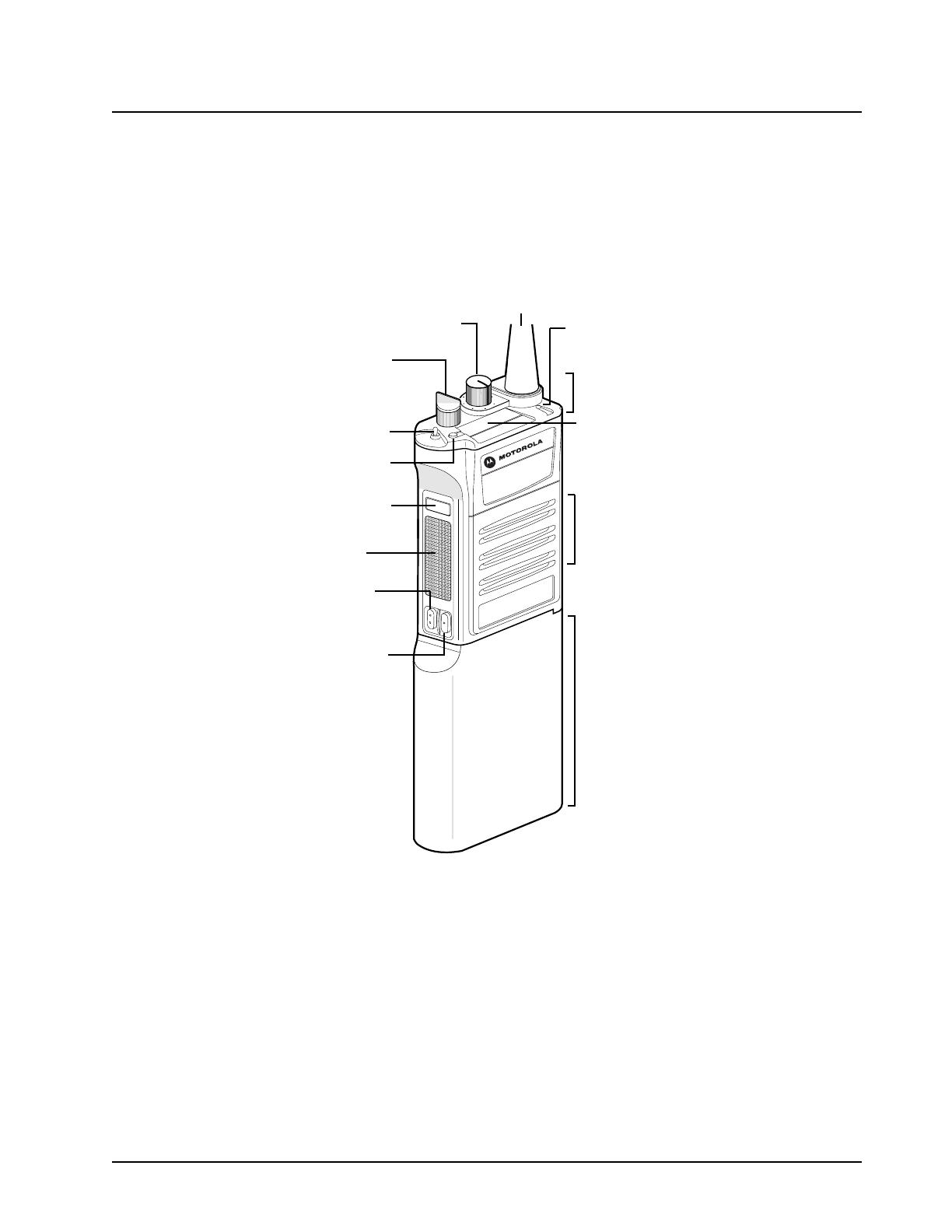
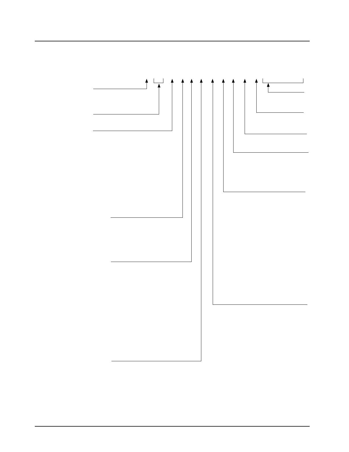
1.1 Physical Features of the Radio
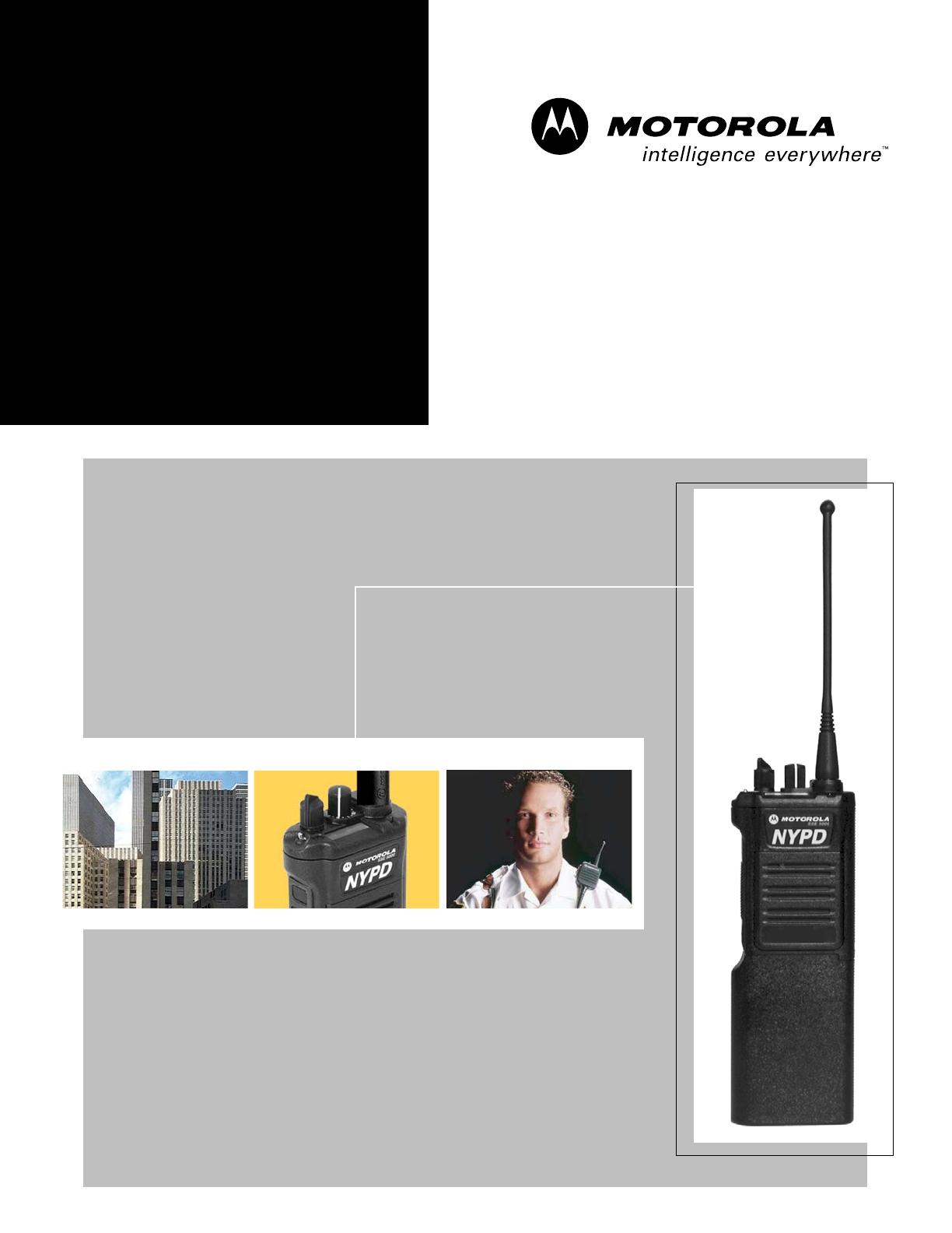
Figure 1-1 shows the physical features of the SSE 5000 portable radio.
Figure 1-1. Physical Features of the SSE 5000 Radio
The SSE 5000 portable radio operates in the UHF Range 2 (450–488 MHz) frequency band. It can
be programmed with up to 96 channels. Earlier versions of the radio, which could be programmed
with up to 48 channels, can be upgraded to 96-channel capability via FLASHport
®
.
1.2 FLASHport
®
The SSE 5000 radio utilizes Motorola’s FLASHport technology. FLASHport allows you to add
software that drives the radio’s capabilities, both at the time of purchase and afterwards. Previously,
changing a radio’s features and capabilities meant significant modifications, or buying a new radio.
Now the radio’s features and capabilities can be upgraded with FLASHport software, similar to how a
computer can be loaded with different software. For information on upgrading the radio’s features
using FLASHport, see the FLASHport User Guide (Motorola publication part number 6881094C35).
7
5
5
3
1
1
Channel
Bank Select
On/Off/
Display (1 line x 8 char,
Display
Monitor
Control
Antenna
Bank
Secure
PTT
Indicator
Speaker/
Battery
Transmit/
Mic
Receive
(LED)
Knob
Knob
Button
Button
Switch
Volume
Button
Button
Select
Top
N
Y
P
D
S
S
E
5
0
0
0
bitmapped LCD)
Channel
Channel
November 11, 2004 6881094C12-A
1-2 Radio Description: Portable Radio Model Numbering System
1.3 Portable Radio Model Numbering System
Position1-TypeofUnit
H=Hand-HeldPortable
Positions2&3-ModelSeries
Position4-FrequencyBand
Lessthan29.7MHz
29.7to35.99MHz
36to41.99MHz
42to50MHz
66to80MHz
74to90MHz
ProductSpecific
136to162MHz
146to178MHz
174to210MHz
190to235MHz
336to410MHz
403to437MHz
438to482MHz
470to520MHz
ProductSpecific
764to870MHz
825to870MHz
896to941MHz
1.0to1.6GHz
1.5to2.0GHz
Valuesgivenrepresentrangeonly;theyare
notabsolute.
Position5-PowerLevel
0to0.7Watts
0.7to0.9Watts
1.0to3.9Watts
4.0to5.0Watts
5.1to6.0Watts
6.1to10Watts
Position6-PhysicalPackages
RFModemOperation
ReceiverOnly
StandardControl;NoDisplay
StandardControl;WithDisplay
LimitedKeypad;NoDisplay
LimitedKeypad;WithDisplay
FullKeypad;NoDisplay
FullKeypad;WithDisplay
LimitedControls;NoDisplay
LimitedControls;BasicDisplay
LimitedControls;LimitedDisplay
RotaryControls;StandardDisplay
EnhancedControls;EnhancedDisplay
LowProfile;NoDisplay
LowProfile;BasicDisplay
LowProfile;BasicDisplay,FullKeypad
Position7-ChannelSpacing
1=5kHz
2=6.25kHz
3=10kHz
4=12.5kHz
5=15kHz
6=20/25kHz
7=30kHz
9=Variable/Programmable
SSE5000ModelNumber:
Position:
Position8-PrimaryOperation
Conventional/Simplex
Conventional/Duplex
TrunkedTwinType
DualModeTrunked
DualModeTrunked/Duplex
TrunkedTypeI
TrunkedTypeII
FDMA*DigitalDualMode
TDMA**DigitalDualMode
SingleSideband
GlobalPositioningSatelliteCapable
AmplitudeCompandedSideband(ACSB)
Programmable
*FDMA=FrequencyDivisionMultipleAccess
**TDMA=TimeDivisionMultipleAccess
Position9-PrimarySystemType
Conventional
PrivacyPlus
ClearSMARTNET
AdvancedConventionalStat-Alert
EnhancedPrivacyPlus
Nauganet888Series
JapanSpecializedMobileRadio(JSMR)
Multi-ChannelAccess(MCA)
CoveragePLUS
MPT1327*-Public
MPT1327*-Private
Radiocom
ToneSignalling
BinarySignalling
Phonenet
Programmable
SecureConventional
SecureSMARTNET
*MPT=MinistryofPostsandTelecommunications
Position10-FeatureLevel
1=Basic
2=LimitedPackage
3=LimitedPlus
4=Intermediate
5=StandardPackage
6=StandardPlus
7=ExpandedPackage
8=ExpandedPlus
9=FullFeature/
Programmable
Position11-Version
VersionLetter(Alpha)-MajorChange
Position12-
UniqueModelVariations
C=Cenelec
N=StandardPackage
Positions13-16
SPModelSuffix
123 4 56 7 8 910111213141516
H10 S DD 9 P W 6 A N S P 0 1
10=SSE5000
A
B
C
D
F
G
H
J
K
L
M
=
=
=
=
=
=
=
=
=
=
=
P
Q
R
S
T
U
V
W
Y
Z
=
=
=
=
=
=
=
=
=
=
A
B
C
D
E
F
=
=
=
=
=
=
A
B
C
D
E
F
G
H
J
K
L
M
N
P
Q
R
=
=
=
=
=
=
=
=
=
=
=
=
=
=
=
=
A
B
C
D
E
F
G
H
J
K
L
M
P
=
=
=
=
=
=
=
=
=
=
=
=
=
A
B
C
D
E
F
G
H
J
K
L
M
N
P
Q
W
X
Y
=
=
=
=
=
=
=
=
=
=
=
=
=
=
=
=
=
=
MAEPF-27326-A

6881094C12-A November 11, 2004
Radio Description: SSE 5000 UHF Range 2 (450–488 MHz) Model Chart 1-3
1.4 SSE 5000 UHF Range 2 (450–488 MHz) Model Chart
MODEL NUMBER DESCRIPTION
H10SDD9PW6AN UHF Range 2 (450–488 MHz), 2–5 Watts, SSE 5000
ITEM NUMBER DESCRIPTION
X — Antenna, UHF (Refer to Section A.1: “Antennas” on page A-1)
X — Battery (Refer to Section A.2: “Batteries” on page A-1)
X NUE7337_ Board, Transceiver, UHF Range 2 (450–488 MHz)
X NCN6186_ Board, VOCON *
X — Cable, Programming (Refer to Section A.8: “Programming Cables” on page A-2)
X — Case, Carrying (Refer to Section A.3: “Carrying Accessories” on page A-1)
X — Charger (Refer to Section A.4: “Chargers and Charger Accessories” on page A-1)
X NTN7061_ Cover, Accessory Connector
X NNTN4709_ Kit, Belt Clip
X NNTN4825_ Kit, Chassis, Back
X NNTN4826_ Kit, Chassis, Front
X 8485687E01 Kit, Control Flex
X NNTN4468_ Kit, Hardware
X NNTN4467_ Kit, Housing
X 8485791E01 Kit, Speaker Mic Flex
X — Mic Accessories (Refer to Section A.7: “Microphones and Microphone Accessories” on page A-2)
X NNTN4006_ Module, Encryption, DES, DES-XL, DES-PFB
X
X — Surveillance Accessories (Refer to Section A.9: “Surveillance Accessories” on page A-2)
Notes:
X = Item Included
* = When ordering a VOCON board, you will be asked to provide the radio's model number, FLASHcode, host
code, and DSP code. You can find this information as follows:
• For the radio model number and FLASHcode, place the radio in test mode (see Section 4.2: “Radio Test
Mode” on page 4-2) and view the scrolling displays.
• For the host code and DSP code, read the radio using the programming cable (RKN4121_ or RKN4122_)
and view the information in the CPS.

November 11, 2004 6881094C12-A
1-4 Radio Description: Specifications for UHF Range 2 (450–488 MHz) Radios
1.5 Specifications for UHF Range 2 (450–488 MHz) Radios
All specifications are per Telecommunications Industry Association TIA/EIA-603 unless otherwise
noted.
GENERAL RECEIVER TRANSMITTER
FCC Designation: AZ489FT4861
Temperature Range:
Operating: –30°C to +60°C
Storage: –40°C to +85°C
Power Supply: Nickel-Cadmium Battery (NiCd)
Battery Voltage:
Nominal: 7.5 Vdc
Range: 6 to 9 Vdc
Transmit Current Drain (typical)*:
5W RF Power: 1800 mA
2W RF Power: 1100 mA
Receive Current Drain at Rated Audio
(typical)*: 240 mA
Standby Current Drain (typical)*: 80 mA
Recommended Battery:
NiCd: NTN4595
or NiCd Smart: HNN9033
Optional FM (Factory Mutual) Battery:
NiCd FM: NTN4596*
or NiCd FM (HazMat): NTN4992*
or NiCd Smart FM: HNN9034*
* FM Intrinsically Safe.
Dimensions (H x W x D):
Without Battery (Radio Only):
H W
D
(no antenna) (at cntl top) (at cntl top)
4.7 in. 2.92 in. 1.37 in.
119.5 mm 74.2 mm 34.9 mm
(no antenna) (at bottom) (at PTT)
4.7 in. 2.66 in. 1.27 in.
119.5 mm 67.6 mm 32.2 mm
With Battery:
H W
D
(no antenna) (at cntl top) (at cntl top)
8.5 in. 2.92 in. 1.37 in.
215.9 mm 74.2 mm 34.9 mm
(no antenna) (at bottom) (at PTT)
8.5 in. 2.66 in. 1.27 in.
215.9 mm 67.6 mm 32.2 mm
Weight: (w/ Antenna):
Less Battery: 11.2 oz (316.9 gm)
With NiCd Smart: 15.9 oz (449.4 gm)
With NiCd: 13.7 oz (387.8 gm)
Frequency Range: 450–488 MHz
Bandwidth: 38 MHz
Reference Sensitivity (12 dB SINAD) (typical):
0.25 µV
Intermodulation Rejection (typical): 75 dB
Adjacent Channel Rejection (typical):
25/30 kHz 78 dB
12.5 kHz 68 dB
Spurious Response Rejection (typical): 80 dB
Rated Audio Frequency Output Power:
500 mW
Hum and Noise Ratio (typical):
25 kHz 50 dB
12.5 kHz 43 dB
Audio Distortion (typical): 1.0%
Channel Spacing: 12.5/25 kHz
Frequency Range: 450–488 MHz
Conducted Carrier Output Power Rating:
450–488 MHz: 2–5 Watts
Carrier Frequency Stability (typical)
(–30 to +60°C; 25°C ref.): ±0.0002%
Conducted Spurious Emissions (typical):
70 dBc
FM Hum and Noise Ratio (typical)
(Companion Receiver): 25 kHz 50 dB
12.5 kHz 40 dB
Audio Distortion (typical): 1.5%
Modulation Limiting: 25 kHz ±5.0 kHz
12.5 kHz ±2.5 kHz
Adjacent Channel Power Ratio (ACPR)
(typical): 25 kHz 77 dBc
12.5 kHz 62 dBc
Emissions Designators:
20K0F1E, 16K0F3E, 11K0F3E, 8K10F1D, and
8K10F1E
* Test box will add 25 mA.
Specifications subject to change without notice.
/