Symmons 3606-H321-V-STN Installation guide
- Category
- Sanitary ware
- Type
- Installation guide

Model Numbers Specification
Options/Modifications
Tub/shower trim with hand shower and lever handle
includes wall connection, 30” slide bar, in-line vacuum
breaker, exible metal hose, non-diverter tub spout,
1 mode hand shower and 1 mode showerhead with
standard 2.5 gpm (9.5 L/min) ow restrictor. Shower
trim with hand shower and lever handle includes all of
the above less non-diverter tub spout. Valve trim with
hand shower and lever handle includes all of the above
less non-diverter tub spout and 1 mode showerhead.
Components made from metal and nonmetallic
materials plated in standard polished chrome nish.
Duro™ Trim Series
Operation & Maintenance Manual
3603-H321-V-TRM, 3605-H321-V-TRM, 3606-H321-V-TRM
3603-H321-V-TRM
Valve Trim with Hand Shower
Compliance
-1.5
1.5 gpm (5.7 L/min) flow restrictor
-2.0
2.0 gpm (7.6 L/min) flow restrictor
-SS
Slip spout on any tub/shower unit
3605-H321-V-TRM
Shower Trim with Hand Shower
Note: Append appropriate -sufx to model number.
-ASME A112.18.1/CSA B125.1
3606-H321-V-TRM
Tub/Shower Trim with Hand Shower
-LW
Wide lever handle (chrome finish only)
Warranty
Limited Lifetime - to the original end purchaser in
consumer/residential installations.
5 Years - for industrial/commercial installations.
Refer to www.symmons.com/warranty for complete
warranty information.

2
Dimensions
Notes:
1) All dimensions measured from nominal rough-in (see O as reference).
2) Dimensions subject to change without notice.
Measurements
A Ø 2 1/4”, 57 mm
B 5 7/8”, 149 mm
C 6”, 152 mm right or left
D
Male 1/2” NPT thread must
be recessed 1/4” from
nished wall
E Ref. 77”, 1956 mm
F 4 7/8”, 123 mm
G 5”, 127 mm
H 7 1/2”, 191 mm
I 10”, 254 mm
J Ø 2 1/2”, 64 mm
K
(3606)
Ref. 32”, 813 mm
(3603, 3605)
Ref. 42”, 1067 mm
L 12”, 305 mm
M 3 3/16”, 81 mm
N 3 7/16”, 87 mm
O
Rough-in
2 3/8” ± 1/2”, 60 mm ± 13 mm
P 5 1/4”, 133 mm
Q 7”, 178 mm
R 1/2” NPT
AA
G
G
H
H
K
K
L
L
E
E
B
B
D
D
F
F
I
I
M
M
O
O
Q
Q
R
R
P
P
C
C
Floor
Floor
N
N
JJ

3
Parts Breakdown
Replacement Parts
Item Description Part Number
A
Q
In-line Vacuum
Breaker & 60” Hose
EF-104
B Wall Elbow EF-105
I Hand Shower EF-100
N
O
P
Slide Bar
Assembly
SC-115
C
D
Shower Arm
Flange
300S
E Showerhead 362SH
F*
G
H
S
Diverter Escutcheon
Screws
Mounting Plate
Gasket
T-525-NS
G
L*
M
S
Screws
Escutcheon
Mounting Plate
Gasket
T-470-NS-K009
J Handle Assembly T-617
K Dome Cover RTS-037
R Tub Spout 067
Tools Required for Installation
Adjustable
wrench
Allen wrench
(1/8”)
Phillips head
screwdriver
Plumber tape
Power drill
Silicone
*Note: Apply a bead of silicone around the perimeter of the escutcheons
after installing trim ush with wall. Leave opening on bottom of
escutcheons for weep hole.
Notes:
1) Append -STN to part number for Satin Nickel nish.
2) Append -1.5 or -2.0 to showerhead or hand
shower for low ow.
D
C
H
S
S
F
G
I
J
K
K
J
L
G
M
N
O
P
Q
R
A
B
E

4
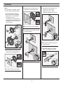
Installation
Note:
For valve body installation, please
see valve body installation guides.
1) Install small plastic mounting
plate (H) to diverter valve (3506
diverter valve = 4-460E-BODY,
3505 diverter valve =
4-458E-BODY) and large plastic
mounting plate (M) to shower valve
(4000-BODY). Secure each with
two screws (G).
2) Attach diverter escutcheon (F) to
small plastic mounting plate (H).
Note: Tabs should snap into place.
3) Attach shower escutcheon (L) to
large plastic mounting plate (M).
Note: Tabs should snap into place.
4) Install dome covers (K) to valves by
turning clockwise.
5) Install diverter handle (3605 and
3606 only) (J) and shower
handle (J) to valves. Secure
handles by tightening set screws.
Note: Handles should be facing the
6 o'clock position.
6) Install tub spout (R) to stub out
pipe. Turn clockwise to secure.
1
1
2
H
G
G
M
F
H
L
M
1
1
2
K
K
1
1
2
J
J
1
2
R

5
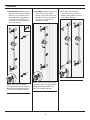
Installation
7a)
Dry Wall Option: R
emove upper
and lower caps (N) from slide bar
brackets. Place slide bar (P) into
desired position. Using brackets
as a guide, carefully drill 3/16"
holes into wall. Remove slide bar
and install anchors.
Notes: Make sure that slide bar
holes and bracket holes are aligned
before drilling. Before drilling bottom
hole, make sure slide bar is plumb.
7b) Stud Option: R
emove upper and
lower caps (N) from slide bar
brackets. Place slide bar (P) into
desired position. Using brackets
as a guide, carefully drill 1/8"
pilot holes into stud.
Notes: Make sure that slide bar holes
and bracket holes are aligned before
drilling. Before drilling bottom hole,
make sure slide bar is plumb.
8) With slide bar (P) in position,
secure to wall using screws (O).
Replace upper and lower caps (N)
onto slide bar brackets.
4
4
1
1
2
2
3
P
N
N
1
1
2
2
3
P
N
N
2
2
1
O
PP
N
N

6
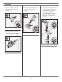
Installation
9) Install wall elbow (B) to stub
out pipe. Tighten set screw
to secure.
10) Attach shower arm (C) and
ange (D) to vertical shower pipe
turning clockwise to tighten.
11) Install showerhead (E) to shower
arm (C). Turn clockwise to
tighten.
12) Attach large end of hand shower
hose (Q) to hand shower wand
(I). Attach small end of hand
shower hose (Q) to in-line
vacuum breaker (A). Connect in-
line vacuum breaker to wall
elbow (B). Turn clockwise to
tighten.
1
2
C
D
3
1
4
2
Q
I
A
Q
B
1
2
B
1
2
E
C

Symmons Industries, Inc. ■ 31 Brooks Drive ■ Braintree, MA 02184 ■ Phone: (800) 796-6667 ■ Fax: (800) 961-9621
Copyright © 2015 Symmons Industries, Inc. ■ www.symmons.com ■ [email protected] ■ ZV-3017 REV 0 ■ 100314
1) Turn shower handle counterclockwise approximately
1/4 turn to put valve in cold position.
2) Turn shower handle counterclockwise approximately
1/2 turn to put valve in warm position.
3) Turn shower handle counterclockwise approximately
3/4 turn to put valve in hot position.
1) Diverter handle facing straight down is for diverter
function 1.
2) 3605: Turn diverter handle counterclockwise one full
revolution for diverter function 2.
3606: Turn diverter handle counterclockwise 1/4 turn
for diverter function 2.
3) 3606-TRM: Turn diverter handle counterclockwise 3/4
turn for diverter function 3.
Temperature Control Diverter Control
Operation & Maintenance
Troubleshooting Chart
Finish is spotting.
Elements in water supply may cause
water staining on nish.
Clean nished trim area with a soft
cloth using mild soap and water or a
non-abrasive cleaner and then quickly
rinse with water.
3605-H321-V-CYL-B-TRM
3606-H321-V-CYL-B-TRM
-
 1
1
-
 2
2
-
 3
3
-
 4
4
-
 5
5
-
 6
6
-
 7
7


Symmons 3606-H321-V-STN Installation guide
- Category
- Sanitary ware
- Type
- Installation guide
Ask a question and I''ll find the answer in the document
Finding information in a document is now easier with AI
Related papers
-
Symmons S0216-TRM Installation guide
-
-
-
-
Symmons Industries 4-163-2.0 Installation guide
-
-
-
-
-
Other documents
-
Moen S3898BN Specification
-
 T & S Brass & Bronze Works B-0490-01 Datasheet
-
Symmons Industries 4700-TRM Installation guide
-
Moen TS21704 Series User manual
-
 T & S Brass & Bronze Works B-0921 Datasheet
-
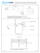 Aquaiaw Shower Arm and Flange, 8 inch, Square, Solid Brass, Brushed Nickel Shower Arm Extension Installation guide
-
WaterWorks USA524 Installation guide
-
 AM Conservation Group SH032C User guide
-
-
3M Jacketed, Flat Cable, .050", 3603 Series Important information


