Western Tornado Poly Hopper (1.25 Cu. Yd.) #96000 Serial #0607-0903 Owner's manual
- Category
- Spreader
- Type
- Owner's manual

January 1, 2017
Lit. No. 95748, Rev. 04
Tornado™ Hopper Spreader
Owner's Manual
Original Instructions
This manual is for WESTERN® Tornado Hopper Spreaders with serial numbers
beginning with 0607–0903.
Western Products, PO Box 245038, Milwaukee, WI 53224‑9538 • www.westernplows.com
This manual supersedes all editions with an earlier date.
CAUTION
Read this document before operating
or servicing the spreader.


Lit. No. 95748/95749, Rev. 04 3 January 1, 2017
TABLE OF CONTENTS
PREFACE .................................................................... 4
Owner's Information .............................................. 4
SAFETY ...................................................................... 5
Safety Denitions .................................................. 5
Warning/Caution Labels ....................................... 5
Serial Number Label .............................................6
Safety Precautions ................................................ 6
Fuses .................................................................... 7
Personal Safety..................................................... 7
Fire and Explosion ................................................7
Cell Phones ...........................................................7
Ventilation ............................................................. 8
Battery Safety .......................................................8
Noise ..................................................................... 8
Vibration ................................................................8
Torque Chart ......................................................... 8
LOADING .................................................................... 9
Certication ........................................................... 9
Material Weights ...................................................9
Load Volume ......................................................... 9
Spreader Specications ...................................... 10
Determining Vehicle Payload .............................. 10
Determining Vehicle Payload Worksheet ............ 11
MOUNTING THE SPREADER ................................. 12
OPERATING THE SPREADER – CAB CONTROL . 15
Starting and Stopping Motor ............................... 15
Adjusting Spinner/Conveyor Speed .................... 15
Blast/Maximum Speed ........................................ 15
Diagnostic Indicator Light ................................... 16
REMOVING THE SPREADER ................................. 17
MAINTENANCE ........................................................ 19
Grease Fittings ................................................... 19
Drive Belt and Chain Tension ............................. 19
Conveyor Belt Tension ........................................ 20
After Each Use .................................................... 21
Storage ............................................................... 21
At the End of Each Season or
After Extended Storage ................................... 22
Fuse Replacement .............................................. 22
Recycle ...............................................................22
Gear Oil Specication ......................................... 22
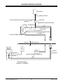
HARNESS WIRING DIAGRAM ................................ 23
TROUBLESHOOTING GUIDE ................................. 24

Lit. No. 95748, Rev. 04 4 January 1, 2017
This manual has been prepared to acquaint you with
the safety information, operation and maintenance of
your new hopper spreader. Please read this manual
carefully and follow all recommendations. This will
help ensure protable and trouble-free operation of
your hopper spreader. Keep this manual accessible. It
is a handy reference in case minor service is required.
When service is necessary, bring your hopper
spreader to your distributor. They know your spreader
best and are interested in your complete satisfaction.
NOTE: This spreader is designed to spread snow
and ice control materials only. Do not use it
for purposes other than those specied in this
manual.
Register your spreader online at www.westernplows.com
OWNER'S INFORMATION
Owner's Name: ______________________________________________________________________
Date Purchased: _____________________________________________________________________
Outlet Name: ______________________________________________ Phone: _________________
Outlet Address: ______________________________________________________________________
Vehicle Model: _______________________________________________ Year: _______________
Spreader Type (Model): ________________________________ Serial #: ______________________
Length: ________________________ Weight: __________________ lb/kg: _________________
PREFACE

Lit. No. 95748/95749, Rev. 04 5 January 1, 2017
SAFETY
Both
Sides
SAFETY DEFINITIONS
NOTE: Indicates a situation or action that can lead
to damage to your spreader and vehicle or other
property. Other useful information can also be
described.
WARNING/CAUTION LABELS
Become familiar with and inform users about the
warning and caution labels on the spreader.
NOTE: If labels are missing or cannot be read, see
your sales outlet.
CAUTION
Indicates a potentially hazardous situation
that, if not avoided, may result in minor or
moderate injury. It may also be used to alert
against unsafe practices.
WARNING
Indicates a potentially hazardous situation
that, if not avoided, could result in death or
serious personal injury.
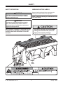
CAUTION
Do not lift spreader by this member.
Lifting here could cause personal
injury and property damage.
67272

Lit. No. 95748/95749, Rev. 04 6 January 1, 2017
SAFETY
SAFETY PRECAUTIONS
Improper installation and operation could cause
personal injury and/or equipment and property
damage. Read and understand labels and the
Owner's Manual before installing, operating, or
making adjustments.
WARNING
• Driver to keep bystanders minimum of
25 feet away from operating spreader.
• Before working with the spreader, secure all
loose-tting clothing and unrestrained hair.
• Before operating the spreader, verify that all
safety guards are in place.
• Before servicing the spreader, wait for
conveyor, auger, and spinner to stop.
• Do not climb into or ride on spreader.
WARNING
Do not install the control for this product in
the deployment path of an air bag. Refer to
vehicle manufacturer's manual for air bag
deployment area(s).
CAUTION
If rear directional, CHMSL light, or brake
stoplights are obstructed by the spreader, the
lights shall be relocated or auxiliary directional
or brake stoplights shall be installed.
WARNING
Overloading could result in an
accident or damage. Do not exceed
GVWR or GAWR ratings as found
on the driver‑side vehicle door
cornerpost. See Loading section to determine
maximum volumes of spreading material.
CAUTION
During the hopper installation we recommend
the addition of an OSHA compliant Backup
Alarm. This alarm is required for OSHA
governed employers.
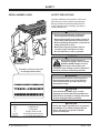
Code Denition
YY 2-Digit Year
MM 2-Digit Month
DD 2-Digit Day
LL 2-Digit Location Code
XXXX 4-Digit Sequential Number
ZZZZZZ 5- to 7-Digit Assembly PN
SERIAL NUMBER LABEL
(Located on driver's side, next
to warning/caution label.)

Lit. No. 95748/95749, Rev. 04 7 January 1, 2017
SAFETY
CAUTION
Disconnect electric and/or hydraulic power
and tag out if required before servicing or
performing maintenance.
NOTE: Lubricate grease ttings after each use.
Use a good quality multipurpose grease.
FUSES
The electrical system contains several blade-style
automotive fuses. If a problem should occur and
fuse replacement is necessary, the replacement
fuse must be of the same type and amperage rating
as the original. Installing a fuse with a higher rating
can damage the system and could start a re. Fuse
Replacement, including fuse ratings and locations, is
located in the Maintenance section of this Owner's
Manual.
PERSONAL SAFETY
• Remove ignition key and put the vehicle in park or
in gear to prevent others from starting the vehicle
during installation or service.
• Wear only snug-tting clothing while working on
your vehicle or spreader.
• Do not wear jewelry or a necktie, and secure long
hair.
• Wear safety goggles to protect your eyes from
battery acid, gasoline, dirt, and dust.
• Avoid touching hot surfaces such as the engine,
radiator, hoses, and exhaust pipes.
• Always have a re extinguisher rated BC handy,
for ammable liquids and electrical res.
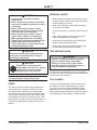
FIRE AND EXPLOSION
Be careful when using gasoline. Do not use gasoline
to clean parts. Store only in approved containers away
from sources of heat or ame.
CELL PHONES
A driver's rst responsibility is the safe operation of
the vehicle. The most important thing you can do
to prevent a crash is to avoid distractions and pay
attention to the road. Wait until it is safe to operate
Mobile Communication Equipment such as cell phones,
text messaging devices, pagers, or two-way radios.
CAUTION
DO NOT leave unused material in
hopper. Material can freeze or solidify,
causing unit to not work properly.
Empty and clean after each use.
WARNING
Gasoline is highly ammable and gasoline
vapor is explosive. Never smoke while
working on vehicle. Keep all open ames
away from gasoline tank and lines. Wipe up
any spilled gasoline immediately.
CAUTION
• Do not operate a spreader in need of
maintenance.
• Before operating the spreader, reassemble
any parts or hardware removed for cleaning
or adjusting.
• Before operating the spreader, remove
materials such as cleaning rags, brushes,
and hand tools from the spreader.
• Before operating the spreader, read the
engine owner's manual, if so equipped.
• While operating the spreader, use auxiliary
warning lights, except when prohibited by law.
• Tighten all fasteners according to the
Torque Chart. Refer to Torque Chart for the
recommended torque values.

Lit. No. 95748/95749, Rev. 04 8 January 1, 2017
SAFETY
VENTILATION
BATTERY SAFETY
NOISE
Airborne noise emission during use is below 70 dB(A)
for the spreader operator.
VIBRATION
Operating spreader vibration does not exceed 2.5 m/s2
to the hand-arm or 0.5 m/s2 to the whole body.
TORQUE CHART
1/4-20 10
91
54
1/4-28 12
11
71
5/16-1
81
50 212
5/16-2
41
70 240
3/8-16 269 376
3/8-24 29
74
20
7/16-1442
96
06
7/16-20
9/16-12
9/16-18
5/8-11
5/8-18
3/4-10
3/4-16
7/8-9
7/8-14 47
46
69
64
49
091-8
1-12 70
49
95
1/2-13
1/2-20
11.9
13.7
24.6
27.3
43.6
26.9
53.3
93
148
49.4
69.8
77.9
106.4
120.0
8.4
9.7
17.4
19.2
30.8
35.0
49.4
55.2
75.3
85.0
M6 x 1.00
M12 x 1.75
M8 x 1.25
M14 x 2.00
M10 x 1.50
M27 x 3.00
M22 x 2.50
M30 x 3.50
M24 x 3.00
M20 x 2.5011.1
19.5
38.5
67
107
7.7
613
778
1139
1545
450
428
562
796
1117
M33 x 3.50
M36 x 4.00
2101
2701
1468
1952
325
M16 x 2.00 231167
M18 x 2.50 318222
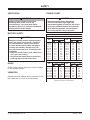
Recommended Fastener Torque Chart
Size Size
Torque (ft-lb)
Grade
5
Grade
8
Metric Fasteners Class 8.8 and 10.9
These torque values apply to fasteners
except those noted in the instructions.
Torque (ft-lb)
Grade
5
Grade
8
Size Size
Torque (ft-lb)
Class
8.8
Class
10.9
Torque (ft-lb)
Class
8.8
Class
10.9
Inch Fasteners Grade 5 and Grade 8
CAUTION
Batteries normally produce explosive gases
which can cause personal injury. Therefore,
do not allow ames, sparks, or lit tobacco
to come near the battery. When charging or
working near a battery, always cover your
face and protect your eyes, and also provide
ventilation.
• Batteries contain sulfuric acid, which burns
skin, eyes, and clothing.
• Disconnect the battery before removing or
replacing any electrical components.
CAUTION
Read instructions before assembling.
Fasteners should be nger tight until
instructed to tighten according to the Torque
Chart. Use standard methods and practices
when attaching spreader, including proper
personal protective safety equipment.
WARNING
Vehicle exhaust contains lethal fumes.
Breathing these fumes, even in low
concentrations, can cause death. Never
operate a vehicle in an enclosed area without
venting exhaust to the outside.

Lit. No. 95748/95749, Rev. 04 9 January 1, 2017
LOADING
26" (1.3 cu yd)
18" (0.9 cu yd)
12" (0.5 cu yd)
This Owner's Manual covers vehicles that have been
recommended for carrying the hopper spreader. Please
see your local dealer for proper vehicle applications.
CERTIFICATION
WARNING
Overloading could result in an accident or
damage. Do not exceed GVWR or GAWR as
found on the driver‑side cornerpost of vehicle.
WARNING
New untitled vehicle installation of a spreader
requires National Highway Trafc Safety
Administration altered vehicle certication
labeling. Installer to verify that struck load of
snow or ice control material does not exceed
GVWR or GAWR rating label and complies
with FMVSS.
CAUTION
Read and adhere to manufacturer's
ice‑control material package
labeling, including Material Safety
Data Sheet requirements.
MATERIAL WEIGHTS
Density
Material (lb/ft3)(lb/yd3)(kg/m3)
Salt 80 2160 1282
Sand 100 2700 1602
Material densities are approximate and are based on dry,
loose material. It is the responsibility of the operator to
know the weight of the material to be spread and the vehicle
carrying capacity.
LOAD VOLUME

Lit. No. 95748/95749, Rev. 04 10 January 1, 2017
DETERMINING VEHICLE PAYLOAD
1. Install hopper spreader and optional equipment
according to the instructions.
2. Install or attach any other equipment that will be
on the vehicle while the hopper spreader will be in
use (step bumper, trailer hitch, snowplows, etc.).
Fill gas tanks.
3. Obtain the Gross Vehicle Weight Rating (GVWR),
Front Gross Axle Weight Rating (FGAWR) and
Rear Gross Axle Weight Rating (RGAWR) from
the certication label located inside the driver-side
door jamb or door.
4. With the occupants in the truck for normal hopper
spreader operation, weigh the vehicle to obtain
gross vehicle weight (GVW).
WARNING
Overloading could result in an accident or
damage. Do not exceed GVWR or GAWR
ratings as found on the driver‑side door
cornerpost of the vehicle. See Loading
section to determine maximum volumes of
spreading material.
5. Subtract the GVW from the GVWR to determine
the available material payload.
6. Obtain the weight per cubic yard (lb/cu yd) of
the desired material. Divide the weight into the
payload to determine the maximum volume of
material that can be carried.
7. Compare the maximum volume to determine the
maximum height of the material in the hopper
spreader.
8. Fill hopper with the material to the calculated
height. Re-weigh vehicle with occupants and
verify that the GVW, Front Gross Axle Weight,
and Rear Gross Axle Weight are less than the
vehicle's ratings.
9. Repeat Steps 6–8 for each type of material.
Refer to the "Determining Vehicle Payload Worksheet"
for an example and worksheet.
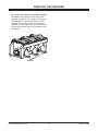
SPREADER SPECIFICATIONS
Spreader
Description
Overall
Length
(in)
Empty
Weight
(lb)
Capacity
Struck
(cu yd)
Capacity
Rounded
(cu yd)
Overall
Width
(in)
Overall
Height
(in)
Recommended
Use
Regular Capacity
7' Hopper Body
Double-Wall Poly
84 550 1.3 1.5 50 37
3/4–1 ton Pickup
Trucks above
8500 lb GVWR
LOADING

Lit. No. 95748/95749, Rev. 04 11 January 1, 2017
LOADING
Determining Vehicle Payload Worksheet
Material Type Example:
Dry Salt
Equipment installed when
vehicle was weighed
7' Poly Hopper
Spreader
Front Gross Axle Weight Rating
(FGAWR) (lb)
Rear Gross Axle Weight Rating
(RGAWR) (lb)
Gross Vehicle Weight Rating
(GVWR) (lb) 8600
Gross Vehicle Weight (empty)
(lb) – 6500
Payload Available
(lb) = 2100
Material Density
(lb/cu yd) ÷ 2160
Maximum Volume
(cu yd) = 0.97
Maximum Height (approximate)
(in) 18
Loaded Front Gross Axle
Weight
(FGAW) (lb)
Loaded Rear Gross Axle
Weight
(RGAW) (lb)
Loaded Gross Vehicle Weight
(GVW) (lb)

Lit. No. 95748/95749, Rev. 04 12 January 1, 2017
MOUNTING THE SPREADER
NOTE: Periodically throughout the snow and ice
control season, verify that mounting devices
are secure.
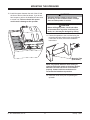
1. Remove the tailgate from the truck.
2. The spreader can be moved into the truck bed
either by lifting the spreader by the four lifting
handles located on the corner legs or by sliding
the spreader into the truck bed from the ground.
3. To lift the spreader into the truck bed from the
ground, stand the spreader up on the feet at the
rear of the spreader. The chute must be removed
and the knobs that secure the chute cover
screwed all the way in.
CAUTION
Before lifting, verify that hopper is empty of
material. The lifting device must be able to
support the spreader's weight as shown in
the spreader specications table.
Lifting Handles
(Both Sides)

Lit. No. 95748/95749, Rev. 04 13 January 1, 2017
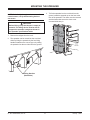
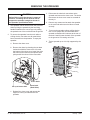
Draw Latch
(Both Sides)
Cross Shaft
Lift up to loosen belt.
MOUNTING THE SPREADER
4. To remove the chute:
a. Release the two draw latches that hold the
chute to the sill; rotate the bottom of the chute
up to loosen the drive belt.
b. Remove the belt from the spinner shaft pulley
and lift the chute off the cross shaft.
5. Position spreader on its feet at the rear of the
truck.
6. Tip the spreader toward the truck until the sill rests
on the rear edge of the truck bed.
7. Lift the rear of the spreader and slide it into the
truck bed. Two or more people are recommended
for this task.
8. Center the spreader in the truck.
9. To assemble the chute to the spreader:
a. Hook the chute hooks over the cross shaft.
b. Rotate the chute up, position the V-belt over
the two pulleys.
c. Lower the chute and fasten it to the sill by
connecting the draw latches. (Refer to the
illustration in Step 4.)

Lit. No. 95748/95749, Rev. 04 14 January 1, 2017
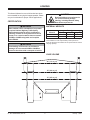
10. Install the spacer between the end of the sill and
the front of the truck bed as shown. If you do not
have a spacer, refer to the Installation Instructions
to create one. Failure to install this spacer
could result in damage to the spreader.
MOUNTING THE SPREADER
Mounting T
abs
(Both Sides)
WARNING
Spreader shall be bolted to vehicle frame.
Do not rely on the tie‑down chains or straps
alone to hold spreader in vehicle.
CAUTION
Before drilling any holes, check both sides
of the material for any wires, fuel lines, fuel
tanks, etc., that may be damaged by drilling.
11. Fasten the spreader to the truck bed using the
mounting tabs and existing holes and hardware.
If there are no holes, refer to the installation
instructions.
NOTE: Pay special attention when drilling or
clamping dissimilar metals to aluminum bodies.
Galvanic corrosion can occur if not handled
properly. Contact vehicle manufacturer for
recommended attachment practices.
12. Install the chute cover prior to operating the
spreader.

Lit. No. 95748/95749, Rev. 04 15 January 1, 2017
OPERATING THE SPREADER – CAB CONTROL
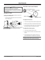
STARTING AND STOPPING MOTOR
1. To start the spreader, press the START/BLAST
button and release. Both the START/BLAST and
OFF buttons will be backlit when motor is running.
Spreader will operate at speed selected on the
speed dial.
2. Press the OFF button to stop motor. The OFF
button operates as emergency stop when
required.
NOTE: The truck ignition must be ON to start the
spreader.
NOTE: If truck ignition is turned OFF while
spreader is running, the motor will stop.
ADJUSTING SPINNER/CONVEYOR SPEED
The speed setting can be adjusted when spreader is
either ON or OFF.
1. Turn speed dial clockwise. Speed will increase as
the number of green LEDs illuminated on speed
dial increases.
2. Turning speed dial counterclockwise will decrease
speed.
Blast/Maximum Speed
1. Press and hold START/BLAST button as long as
maximum speed is needed.
2. Release button when maximum speed is no
longer needed. The control automatically returns
to the "ON" position and the speed shown on the
speed dial.
NOTE: When blast is used, the speed dial does
not move to the maximum speed setting, but
remains at the preset speed.
Speed Dial
Off Button (Emergency
stop when required.)
On/Maximum
Speed Button
Diagnostic
Indicator Light
WARNING
Before starting the spreader, the driver shall
verify that all bystanders are a minimum of
25 feet away from operating spreader.
WARNING
Never operate equipment when under the
inuence of alcohol, drugs, or medications that
might alter your judgment and/or reaction time.
WARNING
Never exceed 45 mph (72 km/h) when loaded
spreader is attached to vehicle. Braking
distances may be increased and handling
characteristics may be impaired at speeds
above 45 mph (72 km/h).
WARNING
Never allow children to operate or climb on
equipment.

Lit. No. 95748/95749, Rev. 04 16 January 1, 2017
OPERATING THE SPREADER – CAB CONTROL
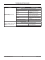
DIAGNOSTIC INDICATOR LIGHT
The diagnostic indicator light located to the right of the
START/BLAST button remains dark unless a problem
with the motor or wiring is detected. The light will ash
a number of ashes in a row, pause, then repeat.
Count the ashes to determine the nature of the
malfunction and refer to diagnostic chart below.
NOTE: Always place cover on the hopper to
prevent moisture buildup. Do not let spreader sit
idle with material in the hopper for an extended
period of time. This can cause material to
compact and reduce or stop the ow of material.
# of
Flashes Problem Possible Cause
0No Fault –
1 No Communication Loss of communication between spreader module and cab control.
Vehicle cable assembly is disconnected or faulty.
2 No Material Flow Spreader is empty or material has bridged in the hopper.
3Excess Current Over 80 amps for 1–2 seconds.
Conveyor belt is stalled.
4No Power Battery fuse is blown, or vehicle cable assembly is disconnected or faulty.
5 Over Heated
Motor is OFF due to spreader module over heating.
Possibly due to excessive current draw or poor thermal contact between spreader
module and conveyor sill.
6Low Voltage Low battery voltage or poor electrical connection of vehicle cable assembly.

Lit. No. 95748/95749, Rev. 04 17 January 1, 2017
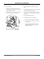
REMOVING THE SPREADER
3. Disconnect the electrical connections at the
spreader and remove the chute cover. The knobs
that secure the chute cover must be screwed all
the way in.
4. Remove any means used to attach the spreader
to the truck bed and ensure the lids are closed
securely.
5. To remove the spreader without a lifting device,
two or more people are recommended. Move
spreader rearward until it balances at the rear of
the bed. Carefully lower the back of the spreader
to the ground so it is resting on its feet.
6. Tip the spreader up so it is fully supported by the
feet.
1. The spreader can be removed from the truck bed
either by lifting the spreader by the four lifting
handles located on the corner legs or by sliding
the spreader out of the truck bed onto the ground.
2. To remove the spreader from the truck without
a lifting device, rst make sure all material has
been removed from the spreader. To empty the
spreader:
a. Remove the chute cover.
b. Remove the chute by releasing the two draw
latches that hold the chute to the sill; rotate
the bottom of the chute up to loosen the drive
belt. Remove the belt from the spinner shaft
pulley and lift the chute off the cross shaft.
c. Reinstall the chute cover and operate the
hopper to convey all material from the
spreader.
Draw Latch
(Both Sides)
Cross Shaft
Lift up to loosen belt.
CAUTION
Before lifting, verify that hopper is empty of
material. The lifting device must be able to
support the spreader's weight as shown in
the spreader specications table.

Lit. No. 95748/95749, Rev. 04 18 January 1, 2017
REMOVING THE SPREADER
7. Do not leave an unsecured spreader standing
on its feet. After pulling the truck away, either
lower the spreader so it is resting on its 6 legs or
properly support it with blocks and secure it as
directed in the Storage section. If lowering the
spreader onto its 6 legs, place spacers under the
legs so the feet at the rear of the spreader are off
the ground.
Spacers

Lit. No. 95748/95749, Rev. 04 19 January 1, 2017
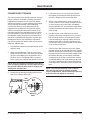
DRIVE BELT AND CHAIN TENSION
To adjust belt tension:
1. Loosen the carriage bolts that hold the spinner shaft.
2. Slide the spinner shaft to increase/decrease tension.
3. After adjusting the shaft, tighten the carriage bolts.
Belt should deect 5/8" between the pulleys.
To adjust the chain tension:
1. Loosen the bolts that hold the motor.
2. Slide the motor to increase or decrease the chain
tension.
3. After adjusting the motor, tighten the bolts. The
chain should deect 1/4" between the sprockets.
NOTE: Overtightening the belt or chain may result
in damage to the motor or gear box bearing.
MAINTENANCE
GREASE FITTINGS
To keep your spreader running smoothly, observe the
following recommendations:
• Lubricate grease ttings after each use and at the
end of each season.
CAUTION
Disconnect electric power at spreader
electrical wiring harness connection and tag
out if required before servicing or performing
maintenance.
Grease after each use with
a good
quality multipurpose grease.
Motor
V-Belt
Deflection of 5/8"
Chain Deflection of 1/4"
Gearbox Input Shaft
Spinner Shaft

Lit. No. 95748/95749, Rev. 04 20 January 1, 2017
MAINTENANCE
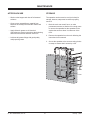
CONVEYOR BELT TENSION
The conveyor drive roller can slip inside the conveyor
belt for a number of reasons, including (1) material
trapped/frozen between the conveyor belt and the
vehicle bed surface, (2) frozen material in the hopper
and (3) improper belt tension. Before adjusting
conveyor belt tension, verify that material is not
trapped/frozen between the conveyor belt and the
vehicle bed surface and that frozen material is not
preventing the belt from operating properly. In either
of these situations, either the drive roller will slip or
the spreader control will sense an overload and will
shut down, signied by the diagnostic indicator light
ashing three times. See Operating the Spreader –
Cab Control section for details on the control and the
diagnostic indicator light.
1. Fully load the hopper with the material that will be
regularly used.
2. Briey test the spreader. If the drive roller slips
inside the conveyor belt or the conveyor belt does
not move, immediately turn the spreader OFF. If
the drive roller is not slipping and the conveyor
belt is moving, the conveyor belt tension is correct.
NOTE: Stop the spreader immediately if the drive
roller is slipping inside the conveyor belt. Running
the spreader when the drive roller is slipping can
damage the conveyor belt.
3. Loosen the two bearing mounting bolts on each
side of the conveyor idler roller.
4. Loosen the jam nut on one of the take-up bolts,
then tighten (clockwise) the take-up bolt one full
revolution. Repeat evenly on the other side.
5. Start the unit to determine if conveyor tension is
correct. If tension is not enough to restart the load
or if the conveyor drive roller slips, immediately
turn the spreader OFF and repeat the steps above
until the load restarts and the conveyor drive roller
does not slip.
6. Run the load for a few minutes and check the
conveyor idler pulley to determine if the conveyor
belt is running closer to one side than the other.
If the belt tracking is centered and the belt is not
rubbing on the side of the sills, retighten the jam
nuts and the bearing mounting bolts on both sides
of the conveyor idler roller.
7. If the conveyor belt is tracking off center, tighten
the take-up bolt on the side that the belt is tracking
towards. Sometimes it is necessary to overtighten
this side to make the belt track back toward center,
then loosen the take-up bolt slightly to maintain
center tracking of the belt. Once the belt tracking
is centered and the belt is not rubbing on the side
of the sills, retighten the jam nuts and the bearing
mounting bolts on both sides of the conveyor idler
roller.
NOTE: The conveyor belt may relax or stretch
after the rst few loads of material and may
require readjustment. Check belt tension after the
rst few loads and adjust as necessary.
Jam
Nut
Idler
Take-Up
Bolt
Bearing
Mounting
Bolts
Page is loading ...
Page is loading ...
Page is loading ...
Page is loading ...
Page is loading ...
Page is loading ...
Page is loading ...
Page is loading ...
-
 1
1
-
 2
2
-
 3
3
-
 4
4
-
 5
5
-
 6
6
-
 7
7
-
 8
8
-
 9
9
-
 10
10
-
 11
11
-
 12
12
-
 13
13
-
 14
14
-
 15
15
-
 16
16
-
 17
17
-
 18
18
-
 19
19
-
 20
20
-
 21
21
-
 22
22
-
 23
23
-
 24
24
-
 25
25
-
 26
26
-
 27
27
-
 28
28


Western Tornado Poly Hopper (1.25 Cu. Yd.) #96000 Serial #0607-0903 Owner's manual
- Category
- Spreader
- Type
- Owner's manual
Ask a question and I''ll find the answer in the document
Finding information in a document is now easier with AI
Related papers
-
Western Utility Mount Kit #75922 Installation guide
-
-
-
-
-
-
-
-
-
Other documents
-
 Salt Dogg 1400475SS Installation guide
-
 Buyers Salt Dogg 1400300SS Owner's manual
-
AGI BCX2 Low Profile Transfer Assembly Manual
-
 SnowEx Bulk Pro SP-1575 Owner's Manual and Installation Instructions
-
 SnowEx V-Maxx G2 VX-2200HO Installation Instructions Manual
-
 New Leader Battery Industry L2020G4 User manual
-
Meyer 62517 User manual
-
Power Acoustik M-944 User manual
-
 SnowEx SP-1575-1 Owner's manual
-
 SnowEx V-Maxx G2 VX-6010 Installation Instructions Manual


