Page is loading ...

SPARTAN
Soldier
Water Jet
Owner’s Manual
Record the VIN Number of your
and give the number to the factory
when ordering parts.
75862000 1-11-17 © 2017 Spartan Tool LLC
SPARTAN TOOL L.L.C.
8 0 0 . 4 3 5 . 3 8 6 6
www.spartantool.com
Soldier
Serial
Number ...........................................

Page 2
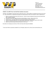
Soldier Overview
Anti-Freeze Recirculation
Selector Valves
Fill Reel
Control
Panel
Pivoting H.P.
Reel
Hose Guide
12 Volt Battery
Anti-Freeze
Tank
200 Gallon Bafed
Water Tank
Anti-Freeze
Supply Valve
Break-Away
Brake Controller
Enclosure Latches
Electric Brakes
Optional Wireless
Remote Control
EZ Lube Bearings
Water Tank
Drain Valve
Locking Tool Box

Page 3
Warnings
―Read the safety and operating instructions before using any Spartan Tool product. Drain and sewer
cleaning can be dangerous if proper procedures are not followed and appropriate safety gear is not
utilized. Read the Engine Owner’s Manual for instruction and safety precautions on engine operation.
― Gasoline is extremely ammable and is explosive under certain conditions.
• Refuel in a well-ventilated area with the engine stopped. Do not smoke or allow ames or sparks
in the area where the engine is refueled or where gasoline is stored.
• Do not overll the fuel tank (there should be no fuel in the ller neck). After refueling, make sure
the tank cap is closed properly and securely.
― Before starting unit, be sure to wear personal protective equipment such as safety goggles or face
shield and protective clothing such as gloves, coveralls or raincoat, rubber boots with metatarsal
guards, and hearing protection.
― Carbon monoxide exhaust and/or gasoline fumes from this equipment can create a hazardous
atmosphere in conned spaces (which may include, but are not limited to, manholes, septic tanks,
closed garages, or other areas which may not be properly ventilated). In particular, excess gasoline
fumes can create an explosion hazard. Such hazardous atmospheres can cause death or severe
injury. Do not operate this equipment in any conned space or area with inadequate ventilation.
Operate this equipment only when located outdoors or in an open, well-ventilated area.
― Ensure the jet hose has been placed in the pipe (minimum of 6 feet suggested) before engaging the
water pressure to prevent the hose from coming out of the pipe prematurely and causing injury.
―Always shut the water pressure off before pulling the hose out of the pipe. Mark the hose a minimum
of 6 feet from the end to help insure the hose is not accidentally pulled out of the pipe while still under
pressure. Shut off the water pressure when the hose mark is encountered. Warning: Portions of the
system can still be under pressure even if the unit is not operating.
―Never point the wash gun at anyone while operating the unit. Injury may result.
―Drains and sewers can carry bacteria and other infectious micro-organisms or materials which can
cause severe illness or death. Avoid exposing eyes, nose, mouth, ears, hands, and cuts and abrasions
to waste water or other potentially infectious materials during drain and sewer cleaning operations. To
further help protect against exposure to infectious materials, wash hands, arms, and other areas of
the body, as needed, with hot soapy water. If necessary, ush mucous membranes with water. Also,
disinfect potentially contaminated equipment by washing such surfaces with hot soapy water and a
strong detergent.
―“California Prop. 65: This product may contain an extremely small amount of lead in the
coating. Lead is a material known to the State of California to cause cancer or reproductive
toxicity.”
― For any questions contact the company at the address shown below.
SPARTAN TOOL L.L.C.
1506 W. Division Street
Mendota, IL 61342
800.435.3866 ♦ Fax 888.876.2371
www.spartantool.com

Page 4
Table of Contents
Soldier Overview ..................................................................................................................................... 3
Warning ................................................................. ................................................................................ 4
Table of Contents ..................................................................................................................................... 5
Soldier Water Jet Specications .............................................................................................................. 6
Soldier Water Jet Features ....................................................................................................................... 7
Towing Instructions ............................................................................................................................. 8-10
Pump and Pressure System .................................................................................................................. 11
High Pressure Water Jetting .................................................................................................................. 12
Water Tank Filling .................................................................................................................................. 12
Operator Controls ............................................................................................................................. 13-14
Engine Operating Procedure ................................................................................................................. 14
Setting up for Operation ........................................................................................................................ 15
Power Rewind Operating Instructions ................................................................................................... 16
Pulsation ................................................................................................................................................ 16
Operating Instructions ......................................................................................................................17-18
Pipe Jetting Procedure .......................................................................................................................... 18
When Obstructions Are Encountered .................................................................................................... 19
Wash Down Kit ...................................................................................................................................... 19
1/4” Drain Hose ...................................................................................................................................... 20
Mobile Hose Reel .................................................................................................................................. 20
Cold Weather Protection ..................................................................................................................21-23
Lubrication and Maintenance ...........................................................................................................24-26
Fuel, Oil, and Coolant Recommendations .............................................................................................. 27
Venturi Pump Attachment (Optional) ..................................................................................................... 28
Pump System Malfunction Chart ........................................................................................................... 29
Electric Braking Systems ..................................................................................................................30-31
Optional Hose Footage Counter 75875000 & Foot Pedal Valve 77773903............................................32
Optional Wireless Remote Control 75880000 ....................................................................................... 33
Tire Safety Information ......................................................................................................................34-36
Safety Reporting Information .................................................................................................................. 37
Soldier Accessories ................................................................................................................................ 38
Soldier Referance Information ................................................................................................................ 39
Warranty Information .............................................................................................................................. 40
For Servicing and Part Information, please refer to the Soldier Service Manual

Page 5
Soldier Water Jet Specications
Pipe Sizes ...................... Up to 12” Max. Water Delivery..... 12.0 GPM
Max. Pressure Delivery ..... 3000 psi
GENERAL
Gross Vehicle Weight Rating (GVWR) .................. 3500 Lbs (1589 kg)
Gross Axle Weight Rating (GAWR) ....................... 3300 Lbs (1498kg)
Trailer Length ........................................................ 126”
Trailer Width ...........................................................57”
Trailer Height...........................................................58”
Hitch ...................................................................... 2” Ball Type (Class II) (Optional Pintle Ring)
Tires .......................................................................ST205-75-R14
Water Tank .............................................................200 Gallon Capacity
Tires (Max Load) ....................................................1760 lbs (each)
Cold Ination Pressure .......................................... 50 PSI/350 kPa (each)
Rim (Diameter X Width X Capacity) .......................14” x 5.5” x 1865 lbs (each)
TRAILER
Model ............................................ FD750D
Cylinders ...................................... 2
Bore & Stroke............................... 3.07 in x 3.07 in
Displacement ............................... 45.5 cu. in
Fuel ............................................... Gasoline, Unleaded 87 Octane Minimum
Fuel Tank Capacity ...................... 8.0 Gal.
Cooling ......................................... Water Cooled/2.9 qt.
Oil Capacity .................................. 2.1 US qt.
Alternator ..................................... 20 Amp
Electric ......................................... 12 VDC
Spark Plug NGK BPR2ES (0.030” Gap)
ENGINE Kawasaki Twin-Cylinder, Water Cooled
Max. Pressure .............. 3000 psi RPM................................1420
Max. Water Output ........12.6 GPM Plungers ......................... 3
Max. Temperature ........ 140º F
PUMP
12V Electric Motor with Variable Speed Controller
REWIND

Page 6
Soldier Water Jet Features
― 3/8” x 250’ high pressure jetting hose (350’ available as option)
― 5/8” x 100’ water supply hose
―180 degree pivoting high pressure hose reel
―Torsion Single-Axle Suspension System wtih Electric Brakes
―Rear mounted operator’s controls
―Electric powered hose rewind
―Hose rewind guide
―Variable Speed Rewind Control
―Pulsation
―Unloader pressure control
― Open and Closed nozzles for 3/8 inch hose
― Easily accessible pump inlet lter assembly
―Pre-Wired lighting with standard 7-Pole plug
―Antifreeze Water Recirculation/Winterization System
―Low water shut off
―Low engine oil pressure shut off
―High engine temperature shut off
―Fillable by either Garden Hose or Hydrant Fill Hose
―Locking tool box
―Quick connect washdown gun & adjustable spray lance
―Manhole hose protection
―12 volt accessory plug
― National Association of Trailer Manufacturers Certied
FEATURES

Page 7
Towing Instructions
Before hitching and towing on public roads, check that the tow vehicle uses a 2” ball on a hitch
rated class II minimum, make sure keeper engages ball to secure hitch. Adjust if necessary.
The following 2 rules may limit your vehicle’s towing capacity and the tank ll when towed.
Determine towing capacity as described below and follow guidelines in using the lowest value
from the 2 rules.
Trailer Hitch
― Check rating of vehicles trailer hitch -
Warning: Class 1 hitches often uses 1 7/8 ball which is unsafe to couple with a 2” hitch.
Class 2 - 3,500 lbs. Towing capacity is required.
Vehicle GCWR (Gross Combined Weight Rating)
— Towing capacity = GCWR minus vehicle weight minus cargo weight minus passenger weight.
Note: GCWR is provided on your vehicle or in vehicle manual.
Vehicle Towing Capacity
― Refer to the Vehicle Owners Manual for listed trailer towing capacity.
― Trailer towing capacity should equal GCWR minus vehicle weight, cargo weight, people weight,
and (vehicle) uids weight.
―Check axle load rotatings.
Wire the plug receptacle to your vehicle as shown below.
Note: The wire colors used on the jet running lights are also indicated in Fig. 7-1 for re-wiring to a different
plug design.
Fig. 7-1
— Always use safety chains.
— Always use trailer lights.
BROWN (RIGHT, STOP & TURN)
WHITE (GROUND)
BLUE (ELECTRIC BRAKES)
GREEN (TAIL & LICENSE)
RED (LEFT, STOP & TURN)
YELLOW (AUXILARY)
NOT USED
BLACK (BATTERY CHARGE)

Page 8
Towing Instructions (cont.)
Towing
1. Check that ball size is same as coupler.
2. Check that Ball Load Rating is the same or greater than Coupler Load Rating.
3. Open clamp on hitch coupler
4. Position hitch coupler above trailer hitch ball.
5. Lower trailer tongue until ball rests in ball socket.
6. Close hitch coupler clamp and secure with a pin or padlock.
7. Connect breakaway cable solidly to bumper or frame of tow vehicle as near to
center as possible. The cable must hang clear of trailer tongue and be long enough
to permit short radius turns without pulling breakaway cable forward.
Fig. 8-1
Fig. 8-2
8. Make sure breakaway cable is in the released position.
Caution: Do not use breakaway cable as a parking brake.
Note: Check location of breakaway cable periodically during each trip. Accidental
application will cause brakes to drag and heat up, causing failure.
Fig. 8-3
Optional
Pintle Ring
75849200

Page 9
Towing Instructions (cont.)
9. Cross safety chains underneath coupler. Allow slack for trailer to turn. Attach chain
hooks securely to tow vehicle frame.
Caution: Always use safety chains. Chains hold trailer if connection fails.
10 Fully retract hitch jack and remove caster wheel. This will provide adequate ground
clearance for transport.
11. Return high pressure reel to towing position, engage the transit lock (Fig. 10-1),
and conrm reel lock (Fig. 10-2) is engaged.
12. You are now ready to tow your trailer.
Caution: Avoid sharp turns. This could bend, create extreme stress or fracture either the
actuator or trailer tongue.
Fig. 9-1
Transit Lock
H.P. Reel
Lock
H.P. Reel
Towing Position

Page 10
Pump and Pressure System
The pump and relief valve are the heart of your jet. They have been specially designed for use
with water temperatures up to 140°F for pipe jetting, but can provide useful water ow for many
other cleaning jobs using the optional wash down gun and special attachments. The positive
displacement pump (each crankshaft revolution has to move a certain amount of water) uses
3 plungers (similar to pistons in an engine) to create water ow. Pressure is not created until
the pump outlet is restricted with a valve or nozzle. The pump, valving, and hoses can support
pressures to 3000 psi.
The regulator valve acts to direct the water ow to the water tank when the hose reel and gun
valves are off, or if nozzles provide too much restriction for total ow. Always use clean water to
keep the regulator valve operating properly. The hose and nozzle are designed to allow full ow
at 3000 psi (at 3200 engine rpm) and the wash down gun operates at 1600 psi max pressure.
If leaks develop in the system between the relief valve and hose reel valve (or gun valve) you
will hear intermittent engine surges as the bypass pressure gradually drops and is built up again
by the pump. Tighten or otherwise repair the leaks for smooth running. Always stop engine and
release pressure before any plumbing changes or repairs.
Because of the inherent hazards with high pressure, use only Spartan high pressure hoses and
components when repairing your machine.
If the nozzles become worn or if the gun is used with the jet hose, the regulator valve allows
the same total ow but at lower pressure because the restriction is lower. To maintain desired
pressure - replace nozzles.
If nozzles become plugged, the regulator valve will direct some of the ow back to the water
tank while providing pressures over 3000 psi. If these pressures are seen with normal engine
speed (3200 rpm), check and clean the nozzles. When using optional lengths of 1/4” hose the
operating pressure can also be over 3000 psi at full gpm. Reducing engines rpm will produce
lower pressures to prevent regulator valve from bypassing off and on. Continued operation at
pressures over 3000 psi can cause engine overheat and reduce engine life.
Clean inlet lter daily (Fig. 10.2). A clogged lter will cause pump to run dry and can cause
expensive damage to pump.
Positive Inlet Filter
Displacement Pump
Regulator

Page 11
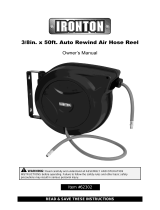
High Pressure Water Jetting
Water Tank Filling
High pressure water jetting is the utilization of high pressure water combined with sufcient water ow to
remove debris in drain/sewer pipes. High pressure water jetting can also be used to remove debris on
surfaces.
A high pressure water jet consists of a pump, a motor or engine, a hose reel, a given length of hose, and
a various assortment of nozzles.
A pipe is cleaned with a high pressure water jet by directing water pressure and ow through a nozzle.
Controlled water pressure and ow propels a water jet through the sewer pipe allowing it to remove and
wash away the obstruction (See Fig. 11.1).
Ideally, a sewer pipe is cleaned from the lower end of the pipe and the hose propels itself to the higher
end of the pipe. By slowly withdrawing the jet hose, the water pressure and ow cleans the line most
effectively. When it is impossible to clean from the lower end of the pipe, the pipe must be water jetted
several times to remove all the debris. A skilled operator can effectively clean a drain/sewer regardless of
the obstacles in his or her way.
Fill the water tank from a clean water source. Always ush rust out of water supply before connecting ll
hose (with garden hose tting) to top ll valve. Trailer jet unit can be lled using 5/8” garden hose on ll
reel or using re hydrant ll. Fire hydrant ll requires re hose with 2” cam lock female quick coupler.
Important Note: If the next 4 items are not followed, cavitation of the pump could occur and reduce
operating efciency and severely damage the pump.
― Use water temperatures under 140°F.
― Ensure that water strainer is clean (check daily or as needed).
― Make sure the strainer valve (between the tank and the pump) is fully open during operations. This
valve stops tank ow to allow strainer service.
―The pump drain valve must be closed. It must not drip when engine is off and strainer valve is open.
How A Jet Works (Penetrating Nozzle) 75800900
Nozzle to be used for initial
penetration of sewer pipe.
(Closed Nozzle) 75800800
Nozzle to be used for thorough
cleaning of sewer pipe.
Fig. 11.1

Page 12
Operator Controls
Pulsation
Control
Ignition
Switch
Murphy Shutdown
Relay Button
Fuse
Variable
Speed Rewind
Selector Dial
Hose
Rewind Control
Button
Fig. 12.2
Choke Throttle
Control Control Panel
H.P. Water Control
Valve
Pressure
Gauge
Pigtail Hose
Guide
Recirculation Swivel
Reel Lock
Transit Lock
12 Volt DC
Outlet
Fig. 12.2
Hydrant
Fill
Optional Wireless
Remote Control

Page 13
Operator Controls (cont.)
Engine Operating Procedure
Fig. 13.1
Start Up
― Check water tank level. This water jet is equipped with a Low Water Shut-Off switch that will prevent
the engine from starting at low water levels.
―Check fuel level.
Note: Also check engine and pump oil levels per manufacturer specications (included).
―Turn high pressure water control valve OFF.
―Hold in red relay button and key start the engine. Choke as necessary.
― Allow the engine to warm up at idle for 3 to 5 minutes before putting engine under load.
Engine Shut-Down
―Turn high pressure water control valve OFF.
―Allow engine to idle for 1 to 2 minutes
― Turn the engine key switch OFF (The engine key switch must be OFF when the engine is not
running to avoid battery draining).

Page 14
Setting up for Operation
Always locate the jet in the driest and safest place possible. Avoid high trafc areas and use ashers
and safety cones. Position the jet so that hose can be pulled directly off of the reel for use. Remember
that jetting is most effective when you jet against the water ow. See Fig. 14-1 for the recommended
positioning of the jet for best visibility during manhole work. Note that loose hose and damaging corners
are minimized when the jet is parked as shown.
When operating upon unlevel ground, position trailer with the hitch (tank sump) end at the downhill
side.
Warning: Trailer must be level for low water shutdown to operate correctly. When trailer is on
an incline with hitch end at the down hill side and tank is empty, enough water can be held in the
lower front corner of tank to keep oat switch in the operating position, defeating this protective feature.
For non-manhole use, allow extra space for handling the hose before it is wound back on the reel or run
the hose directly to the pipe inlet using extra hose guards to protect the hose from cutting when going
around
Warning: Do not unhitch or operate trailer jet unhitched upon unlevel ground.
When unhitching the machine from towing vehicle, always follow these steps:
―Place wheel chocks around trailer jet wheels.
―Disconnect ball hitch by raising lever and jacking hitch up. Disconnect safety chains and light cord
before driving away.
Fig. 14.1

Page 15
Power Rewind Instructions
Pulsation
To Rewind Hose on Reel
―Release reel lock.
― Turn Speed Selector Dial counterclockwise to begin rewind in “Slow” position
―Use panel mounted push button to initiate rewind.
―Adjust Selector Dial to desired rewind speed.
To activate the pulsation feature, turn toggle switch labeled PULSE to the ON position. To deactivate
pulsation, turn toggle switch to OFF position.
Note: Operating pressure will decrease and uctuate when pulsation is activated. See below (Fig. 15- 3)
for approximate pressures.
Pulsation
Electric
Pulsator
Fig. 15-1 Fig. 15-2
PRESSURE SELECTOR
SWITCH SETTING
PULSATION PRESSURE
(PSI)
1000 psi 200 - 700
2000 psi 800 - 1600
3000 psi 1100 - 1700
Fig. 15-3

Page 16
Operating Instructions
Operation:
Release the reel lock and install nozzle and hose guard(s).
Always insert sewer hose several feet into pipe opening before actuating hose reel valve. Never stand in
front of pipe opening when nozzle is near pipe opening. As described in the setup section, work upstream
whenever possible.
Note: At this time, put on safety goggles to prevent eye injury from ying water and debris.
You are ready to start pipe cleaning operations after tank lling and engine starting procedures are
followed. Advance engine throttle to full speed.
Now move H.P. water control valve ON (up) and let out hose as nozzle pulls into pipe. Untwist hose kinks
as necessary before they enter the pipe. Since it is impossible to know exactly what the nozzle “sees”
as it advances in a pipe, always proceed slowly and cautiously. Pull back 1-2 feet for every 4-5 feet of
progress to make sure that the hose is not burying itself or tying itself up in an open cavity or larger pipe.
Continue working up the line while watching and feeling for speed changes as the nozzle makes its way
into a blockage. When working over a manhole, you often will see dirty water, chunks of grease, or debris
ow past as the nozzle penetrates a blockage. When backed up water ows, the line is probably open.
Continue working up the line to open restrictions as desired. Now pull the “working” nozzle back slowly
to re-clean and scour the pipe walls. When working through heavy and long blockages you may have to
ush debris back to machine every 5- 10 ft. Repeat until water runs clean from the pipe.
Do not let engine run at full throttle without load (hose reel valve OFF) for longer than 1-2 minutes.
The Soldier Water Jet will pull out past 250’ but you will nd the going slower because of the pressure
loss from extra hose length. Unless longer operation is common, we recommend the hose extensions be
added only when needed. If moving the jet before the job is done, the hose can be disconnected from the
jet to avoid pulling hose completely out of pipe and restarting.
When nished, turn H.P. water control valve OFF before removing nozzle from pipe.
Hint: Wind white tape around hose (a minimum of 6 ft. from end recommended) to warn of nozzle
being too close to pipe opening.
Wind hose back onto reel, remove hose guard and install hose end and nozzle in holder. Place
high pressure hose in hose holster. Lock reel. Store all parts in tool box compartment. Follow engine shut
down procedure.
Reminder: Engine key switch and any optional equipment, (such as wireless remote control) must be off
to prevent battery drain when not in use.
Reverse setup instructions: Drain tank and disconnect ll hose. Replace manhole cover or pipe caps and
clean up machine before leaving job site.

Page 17
Operating Instructions (cont.)
Pipe Jetting Procedure
Operating Hints:
The following techniques can be tried if the going gets slow.
― Grab the hose into an “S” shape and twist the hose to help it get around corners and off of pipe
edges (See Fig. 18-1).
―Turn water valve off and pull hose back out of line. Look for traces of clay or other material to
determine if nozzle is burying itself outside of pipe.
―Try different nozzle or different pipe openings.
―Walk to nearby buildings and manholes and listen for water sound to determine if hose is going
where it should. The hose may tie itself up in a manhole and need help going into the next pipe.
Use a pole or pipe to guide hose so entering the manhole can be avoided.
Equipment:
Although the Soldier is capable of various high pressure cleaning operations, jetting pipes of 4” - 12”
is typically the major work required of the jet. The hose reel is designed for outdoor applications. See
sections on the mobile hose reel and 1/4” drain hose for indoor or remote applications and for lines
smaller than 6”.
For safety reasons, (unless operating with optional remote control) always operate with 2 people
when the pipe entrance is away from the jet location; one person should stay near the jet to control
the machine operation while the other person works the hose and nozzle. The mobile hose reel
should be used for remote control whenever the second person cannot be seen or heard by the
machine operator.
The sewer hose should always be replaced when reinforcement sleeve can be seen because of a
worn cover.
The Soldier nozzles are designed to match the pressure and ow performance of your jet. They are
key to efcient operation because they convert all of the engine and pump power to water speed for
hose pull and for cleaning impact.
Nozzles “Closed” (75800800) and “Open” (75800900) are standard equipment. See parts section for
part numbers to order additional nozzles or root cutters. Nozzle holes will wear after several months
of continuous use. If the system operating pressure gradually drops, try a new nozzle to check for
wear. Check for nozzle plugging occasionally by removing the nozzle from the hose and holding up to
the light. Clean by inserting small diameter wire if necessary. Plugged nozzles will cause poor hose
pull even though the gauge pressure will show higher.

Page 18
When Obstruction Are Encountered
Wash Down Kit - 73817300
Fig. 18-1 Fig. 18-2
― When obstruction or corners are encountered it may be necessary to manually rotate the hose (See
Fig. 18- 1) to enable feed through that area. The rotation will cause the jetting nozzle to jump over or
around those areas. When it becomes necessary to manually rotate the hose to clear obstructions,
any rotations in one direction must be followed by an equal number in the opposite direction to
prevent kinks from building in the hose.
― At times, it will be necessary to move the hose slightly in and out of the drain line to assist the jetting
nozzle in clearing stubborn clogs, obstructions, or tight corners (See Fig. 18-2).
Note: To use wash-down gun do the following:
1 Turn H.P. water control valve OFF (down).
2 Connect wash-down gun hose to end of 250 ft. hose.
3 Start unit and operate wash-down gun with H.P. water control valve ON (up).
The wash down gun is used to control the spray lance and the 1/4” drain hose. The lance is attached by
pulling back on the ring of the guns quick connect tting. Insert adapter nipple of lance (or 1/4” hose) until
ring can slide back to original position. The lance is equipped with a spray nozzle for general use.
Caution: HOLD HAND GUN/WASH WAND WITH TWO HANDS AT ALL TIMES. Back pressure
buildup on the wash wand/hand gun requires two hands rmly gripping the wand when the trigger
is initially pulled.
Caution: Under no circumstances should you ever operate the wash down gun in the
direction of any other person(s). To do so may cause serious damage to eyes or other bodily
tissue and may even cause death!
Contents of Kit: 1/4” x 75’ hose, lance assembly, 1/4” nozzle, hand gun.

Page 19
1/4” Drain Hose
Mobile Hose Reel -
73816800 (Optional)
The 1/4” hose and nozzle may be used to clean smaller diameter lines. Attach the 1/4” hose to the forward
end of the wash down gun as described on the previous page.
Use the 1/4” drain hose on lines 2” - 4” similar to the reel hose. Again, use care not to discharge water
unless the hose is in the pipe. On inside lines, use short bursts of the gun to limit water backup.
If 75’ or 100’ 1/4” hoses are used with the reel hose, the pressure gauge may read more than 2800 psi.
Adjust engine speed to reduce to desired pressure to avoid engine overheat.
The mobile hose reel (Fig. 19.1) is used for remote
use and control of the sewer hose. 400’ total length
of hose is the practical maximum with the 250’ or
150’ length on the machine reel and the balance
on the mobile reel. To use, attach the machine reel
hose to the valve of the mobile reel. Attach nozzle
to mobile reel hose and make sure the mobile reel
valve is off (handle perpendicular to valve body).
Start jet as usual and open machine hose reel valve.
Now move the mobile reel to the pipe opening and
use as before, using the mobile valve to control
water ow (put hose in pipe before opening valve).
To rewind hose, stand on front plate and use crank
provided.
PART NO DESCRIPTION
77719500 1/4" X 75' Hose
Standard Equipment Optional Equipment
PART NO DESCRIPTION
77719400
77708700
1/4” x 50’ Hose
1/4" X 100' Hose
Fig. 19.1
DESCRIPTION
PART NUMBER
QTY
ITEM
DISC, SIDE HP REEL
75800405
2
5
BEARING W/BALL INSERT
75800404
2
4
DISC WASHER73853200
2
3
TENSIONER, CAM LOCK BRAKE
73828400
1
2
PLASTIC HANDLE W/ BOLT & NUT
79827800
1
1
6HANDLE ASSY, MOBILE HOSE REEL
77752601
1
Replacement Parts

Page 20
Cold Weather Protection
The Soldier comes equipped with versatile anti-freeze system that allows the user to choose
between different levels of protection.
Antifreeze Recirculation: Full Winterization
The pump and all hoses charged with anti-freeze solution. Anti-freeze is conserved by re-circulating back
to anti-freeze tank.
Water Recirculation: Temporary Freeze Resistance
Water is re-circulated through hoses and returned to main water tank.
Fig. 20.3
Fig. 20.1
Fig. 20.2
Fill Reel Hose
Recirculation Fitting
H.P Hose
Recirculation Fitting
Recirculation
Valve
/