Page is loading ...

PRODUCT MANUAL
Power Cable Feed
© 2020 Spartan Tool LLC
Part #04421100 (Rev. G) 2020-011
Spartan Tool LLC | 1618 Terminal Road | Niles, MI 49120
order by phone 800.435.3866 order online SpartanTool.com

2
WARNINGS & INTRODUCTION ..........................................................................................3
Introduction ....................................................................................................................3
CABLE SAFETY GUIDE .................................................................................................. 4
Attaching the Cable Safety Guide to the Power Cable Feed .......................................................................4
SETTING CABLE SIZE ...................................................................................................5
Setting Your Spartan Power Cable Feed Cable Size ...............................................................................5
Setting Cable Size ..............................................................................................................5
PARTS & ASSEMBLY ....................................................................................................6
Universal Power Feed (04221000) ...............................................................................................6
Power Feed Assembly (04217500) ...............................................................................................7
Bearing Block Assembly, Long (04224000) .......................................................................................8
Bearing Block Assembly, Short (44219900) .......................................................................................9
Wheel Carrier Body Comp, Long (44119600) ................................................................................... 10
Wheel Carrier Body Comp, Short (44119700) ................................................................................... 10
INSTALLATION INSTRUCTIONS ........................................................................................11
Installation Instructions for Model 1065 & 2001 ................................................................................ 11
Installation Instructions for Model 300 ......................................................................................... 12
Installation Instructions for Model 100 ......................................................................................... 13
OPERATING INSTRUCTIONS ...........................................................................................14
CLEANING OPERATION ................................................................................................15
DISASSEMBLY & REASSEMBLY .........................................................................................15
Disassembly of Short Bearing Blocks .......................................................................................... 16
Disassembly of Long Bearing Blocks ........................................................................................... 17
Disassembly of Short Bearing Blocks .......................................................................................... 18
Re-Assembly of Short Bearing Blocks .......................................................................................... 18
Re-Assembly of Long Bearing Blocks .......................................................................................... 19
INSTRUCTIONS .......................................................................................................20
WARRANTY INFORMATION ............................................................................................22
Contents

3
Warnings & Introduction
• Read the safety and operating instructions before using any Spartan Tool products. Drain and sewer cleaning can be dangerous if
proper procedures are not followed and appropriate safety gear is not utilized.
• Before starting unit, be sure to wear personal protective equipment such as safety goggles or face shield and protective clothing
such as gloves, coveralls or raincoat, rubber boots with metatarsal guards, and hearing protection.
• Drains and sewer can carry bacteria and other infectious micro-organisms or materials which can cause death or severe illness. Avoid
exposing eyes, nose, mouth, ears, hands, and cuts and abrasions to waste water or other potentially infectious materials, wash hands,
arms and other areas of the body, as needed, with hot, soapy water and, if necessary, flush mucous membranes with water. Also,
disinfect potentially contaminated equipment by washing such surfaces with a hot soapy wash using a strong detergent.
• For any questions, contact the company at the address shown below.
CALIFORNIA PROP. 65
This product may contain an
extremely small amount of lead in the
coating. Lead is a material known to
the State of California to cause cancer
or reproductive toxicity.
CONTACT US
Spartan Tool LLC
1618 Terminal Road
Niles, MI 49120
800.435.3866
SpartanTool.com
INTRODUCTION
The Spartan Tool Power Cable Feed with "dial-a-cable" reflects the latest improvement in the marketplace. The operation, repair,
and maintenance of the Power Feed are simple to accomplish. These features allow a quick change for cable size and provide easy
maintenance. The Power Feed, which weighs just over 10 pounds, will feed and retrieve up to 30 feet per minute.
A universal mounting plate allows adaptation to current Spartan Model 1065s, 300s, and 100s. (The Model 2001 does not need a
mounting plate.) The power cable feed can be used on cable size from ⁄" to ¾".
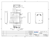
Spartan Tool, LLC strongly recommends the use of a Spartan Cable Safety Guide (44225300) with the Power Cable Feed unit
(see Fig. 1). The Cable Safety Guide attaches to the front of the Power Feed unit, and is intended to help protect the operator from
possible cable buckling and other hazards associated with handling rotating cable. Contact Spartan Tool, LLC at (800) 435-3866 or
www.SpartanTool.com with questions regarding the Cable Safety Guide.

4
Cable Safety Guide
ATTACHING THE CABLE SAFETY GUIDE TO THE POWER CABLE FEED
Disconnect the cable machine from its power source to avoid accidental starting. Pick up the Cable Safety Guide and place the spring
against the hub on the Power Cable Feed and turn it counterclockwise until the spring rests against the plate behind the hub.
Reconnect the power by plugging in the machine. Ensure the electrical switch on the machine is in the forward position. Ensure the
adjusting knob on the feed has been tightened until it makes contact with the cable. Place the lever (actuator assembly) midway
between the "N" (neutral) and "F" (Forward) position to allow the cable to enter the Cable Safety Guide slowly. Depress the foot pedal to
engage the machine and allow the end of the cable the exit the Cable Safety Guide. Release the footpedal.
Disconnect the machine from its power source, and attach the selected tool to the cable. Move the machine as close to the entry point
of the pipe as possible. The end of the Cable Safety Guide and attachment should be within inches of the pipe. Reconnect the power.
WARNING: Unexpected machine start up can cause death or severe injury.
Disconnect the machine from its power source before installing, servicing or removing the Power Cable Feed, Cable Safety Guide, cable
tools and cutters, or other machine components.
FIG 1
SPARTAN TOOL
NILES, MI 49120
DATE
SIZE SCALE
DRAWN BY ECO
DRAWING NUMBER
SHEET NUMBER
REV
TITLE
THIRD ANGLE PROJECTION
UNLESS OTHERWISE SPECIFIED
DIMENSIONS ARE IN INCHES
TOLERANCES
WARNING: THIS DRAWING IS
GENERATED FROM 3D BODY DATA
AND ANY GEOMETRY CHANGES
SHOULD BE CARRIED OUT
IN 3D ONLY.
THIS DOCUMENT CONTAINS
PROPRIETARY INFORMATION AND
SUCH INFORMATION MAY NOT BE
DISCLOSED TO OTHERS FOR ANY
PURPOSE NOR USED FOR
MANUFACTURING PURPOSES
WITHOUT WRITTEN PERMISSION
FROM SPARTAN TOOL L.L.C.
POWER FEED, 300 READY
7/27/2020 KTD -1 of 1
04221000-WITH
CABLE GUIDE
1/4
B
.XX = ± .01 .XXX = ± .005
FRACTIONS = ± 1/64
ANGLES = ± 1°
CRITICAL DIMENSION
REV ECO DATE DESCRIPTION APPROVED

5
SETTING YOUR SPARTAN POWER CABLE FEED CABLE SIZE
Setting Cable Size
SETTING CABLE SIZE
1. To adjust for cable size, push in on the Power Feed Select Knob located on the bottom of the bearing blocks to unlock from setting.
2. Turn knob clockwise and pull out. As each cable setting is reached the knob can be felt locking in. The body assembly will move in
for smaller cable diameters and out for larger cable diameters.
3. Rotating the Dial-A-Cable through the various settings and matching the dial label will make it easy to adjust cable size by feel.
4. Follow the chart (Fig. 3) to set your Dial-A-Cable for the cable size you have selected. Make sure both right and left block settings are
the same.
FIG 2
Cable diameter (inches) Set Power Cable Feed
" ⁄
" or " ⁄
½" or .55" .55
" or .66" .66
¾" ¾
FIG 3

6
Parts & Assembly
UNIVERSAL POWER FEED (04221000)
Universal Unit ts Model 100 - 300 - 1065 machines
Item Part Number Description Qty.
1 00113600 Screw, hex head cap ¼-20 x ⁄ 2
2 00162400 Washer, flat ⁄ USS 2
3 00167000 Internal Tooth Lockwasher 2
4 03409000 Bushing Lock 1
5 04217599 Spartan Power Cable Feed 1
SCREW, HX HD CAP 1/4-20 X 5/8001136002
1
WASHER, FLAT 3/16 USS
0016240022
INTERNAL TOOTH LOCKWASHER0016700023
BUSHING LOCK034090001
4
SPARTAN POWER CABLE FEED - 2001-0421750015
DESCRIPTION
PART NUMBER
QTY
ITEM
SPARTAN TOOL
NILES, MI 49120
DATE
SIZE SCALE
DRAWN BY ECO
DRAWING NUMBER
SHEET NUMBER
REV
TITLE
THIRD ANGLE PROJECTION
UNLESS OTHERWISE SPECIFIED
DIMENSIONS ARE IN INCHES
TOLERANCES
WARNING: THIS DRAWING IS
GENERATED FROM 3D BODY DATA
AND ANY GEOMETRY CHANGES
SHOULD BE CARRIED OUT
IN 3D ONLY.
THIS DOCUMENT CONTAINS
PROPRIETARY INFORMATION AND
SUCH INFORMATION MAY NOT BE
DISCLOSED TO OTHERS FOR ANY
PURPOSE NOR USED FOR
MANUFACTURING PURPOSES
WITHOUT WRITTEN PERMISSION
FROM SPARTAN TOOL L.L.C.
POWER FEED, 300 READY
7/27/2020 rwilson -1 of 1
04221000
1/2
B
.XX = ± .01 .XXX = ± .005
FRACTIONS = ± 1/64
ANGLES = ± 1°
CRITICAL DIMENSION
REV ECO DATE DESCRIPTION APPROVED
5
1
3
2
4
(9.17)
(12.41)
(11.39)

7
Parts & Assembly
POWER FEED ASSEMBLY (04217500)
Item Part Number Description Qty.
14 44223900 2001 Actuator Assembly 1
13 44220110 Decal, Dial-A-Cable Detent 2
12 44219900 Assy, Bearing Block 2
11 04224000 Bearing Block Assy Long 1
10 04220000 Decal Brg Plate Mod 75 Feed 1
9 04218700 Mounting Plate 1
8 04218600 Plate Brg Mod 75 Feed 2
7 04218300 Plate Stationary 75 Feed 2
6 04134900 Nut, Acorn Cap ⁄-18 6
5 02856900 Knob, ⁄-16 Black #35K 1
4 00480300 Screw, hex hd cap ⁄-18 x 3¼ 4
3 00169500 Screw, hex hd cap ⁄-18 x 3½ 2
2 00167100 Internal Tooth Lockwasher 6
1 00162600 Washer, flat ⁄ USS 6
2001 ACTUATOR ASSY44223900114
DECAL, DIAL A CABLE DETENT44220110213
ASSY, BEARING BLOCK 44219900212
BEARING BLOCK ASSY LONG04224000111
DECAL BRG PLATE MOD 75 FEED04220000
1
10
MOUNTING PLATE0421870019
PLATE BRG MOD 75 FEED0421860028
PLATE STATIONARY 75 FEED0421830027
NUT ACORN CAP 5/16-18
0413490066
KNOB, 3/8-16 BLACK #35K02856900
15
SCREW, HEX HD CAP 5/16-18 x 3-1/4
0048030044
SCREW, HEX HD CAP 5/16-18x3-1/20016950023
INTERNAL TOOTH LOCKWASHER0016710062
WASHER, FLAT 5/16 USS
0016260061
DESCRIPTION
PART NUMBER
QTY
ITEM
SPARTAN TOOL
MENDOTA, IL 61342
DATE
SIZE SCALE
DRAWN BY ECO
DRAWING NUMBER
SHEET NUMBER
REV
TITLE
THIRD ANGLE PROJECTION
UNLESS OTHERWISE SPECIFIED
DIMENSIONS ARE IN INCHES
TOLERANCES
WARNING: THIS DRAWING IS
GENERATED FROM 3D BODY DATA
AND ANY GEOMETRY CHANGES
SHOULD BE CARRIED OUT
IN 3D ONLY.
THIS DOCUMENT CONTANINS
PROPRIETARY INFORMATION AND
SUCH INFORMATION MAY NOT BE
DISCLOSED TO OTHERS FOR ANY
PURPOSE NOR USED FOR
MANUFACTURING PURPOSES
WITHOUT WRITTEN PERMISSION
FROM SPARTAN TOOL L.L.C.
POWER FEED ASSY-MOD
75-1065-300
3/6/14 RW 8099 1/1
K
04217500
1=4
B
.XX = .03 .XXX = .005
FRACTIONS = 1/64
ANGLES = 1~
REV DATE ECO DESCRIPTION APPROVED
J3/6/2014 8099 REDRAWN FROM 2-18-83 ORIGINAL; REPLACE 44249900 WITH 04218701 RW
K8/21/2014 8099 ITEM 9 WAS: 04218701; NOW: 04218700 RW
L7/9/2019 8485 ITEM 13: 44220110, WAS 44220100
3 1
4 1
9
8
13
7
12
7
14
8
10
5
13
11
6 2

8
Parts & Accessories
BEARING BLOCK ASSEMBLY, LONG (04224000)
Item Part Number Description Qty.
1 00113700 Screw, hex hd ¼-20 x ¾ 4
2 01921801 Screw, march rd hd sl 8-32 x ½ 1
3 03312001 Nut kep #8-32 zinc plates 1
4 03415700 Bushing & Ball Assembly 1
5 04217900 Block Bearing Long Mod 75 Feed 1
6 04219000 Cap End Weld Assembly 75 1
7 04220100 Spring hvy duty Mod 75 Feed 1
8 04220610 Top Knob, Power Feed 1
9 44119600 Wheel Carrier Body Comp (long) 1
10 44221900 2001 Cover Spring 1
11 44230100 2001 Spring Feed Ext 1
SCREW, HEX HD 1/4-20 X 3/40011370041
SCREW, MACH RD HD SL 8-32 x 1/2
0192180112
NUT KEP #8-32 ZINC PLATED0331200113
BUSHING & BALL ASSEMBLY0341570014
BLOCK BEARING LONG MOD 75 FEED042179001
5
CAP END WELD ASY 750421900016
SPRING HVY DUTY MOD 75 FEED042201001
7
TOP KNOB, POWER FEED0422061018
WHEEL CARRIER BODY COMP (LONG)4411960019
2001 COVER SPRING44221900110
2001 SPRING FEED EXT
44230100111
DESCRIPTIONPART NUMBERQTYITEM
SPARTAN TOOL
MENDOTA, IL 61342
DATE
SIZE SCALE
DRAWN BY ECO
DRAWING NUMBER
SHEET NUMBER
REV
TITLE
THIRD ANGLE PROJECTION
UNLESS OTHERWISE SPECIFIED
DIMENSIONS ARE IN INCHES
TOLERANCES
WARNING: THIS DRAWING IS
GENERATED FROM 3D BODY DATA
AND ANY GEOMETRY CHANGES
SHOULD BE CARRIED OUT
IN 3D ONLY.
THIS DOCUMENT CONTAINS
PROPRIETARY INFORMATION AND
SUCH INFORMATION MAY NOT BE
DISCLOSED TO OTHERS FOR ANY
PURPOSE NOR USED FOR
MANUFACTURING PURPOSES
WITHOUT WRITTEN PERMISSION
FROM SPARTAN TOOL L.L.C.
BEARING BLOCK ASSEMBLY
(LONG)
4/13/17 DL 8335 1 OF 1
D
04224000
1:4
B
.XX = .01 .XXX = .005
FRACTIONS = 1/64
ANGLES = 1
1
1
2
2
3
3
4
4
A A
B B
04224000 BEARING BLOCK ASSY LONG REV ECO DATE DESCRIPTION APPROVED
C 8335 4/13/17 REPLACES DWG DATED 9/3/75 DL
D 8375 10/19/17 ADD (2) 02796200 FITTINGS RW
8
1
6
5
2
10
11
3
4
7
9

9
Parts & Accessories
BEARING BLOCK ASSEMBLY, SHORT (44219900)
FIG 7
Item Part Number Description Qty.
29 04217800 Block Bearing, short Model 75 feed 1
31 00113901 Screw, hex hd ¼-20 x 1 4
33 04219600 Thrust Race 2
34 04219500 Thrust Bearing 1
35 44222100 2001 Knob 1
36 44213800 Dial-A-Cable Block 1
37 44222200 Roll Pin 2001 1
Fig. 8 44119700 Wheel Carrier Body Comp (short) 1

10
Parts & Accessories
WHEEL CARRIER BODY COMP, LONG (44119600)
Item Part Number Description Qty.
24 04217700 Pin Drive, Model 75 feed 1
26 04219700 Bearing Drive, Model 75 feed 1
27 04219800 Washer, 75 Feed stainless 2
28 04219900 Ring Retaining, external 1
30 44250200 O-Ring Seal, wheel carrier 1
32 04218400 Body Wheel Carrier w/hole long (incl.
Item 30) 1
FIG 6
WHEEL CARRIER BODY COMP, SHORT (44119700)
Item Part Number Description Qty.
21 04218500 Body Wheel Carrier w/holy long (incl.
Item 30) 1
26 04217700 Pin Drive, Model 75 feed 1
27 04219700 Bearing Drive, Model 75 feed 1
28 04219800 Washer, 75 feed stainless 2
29 04219900 Ring Retaining, external 1
30 44250200 O-Ring Seal, wheel carrier 1
FIG 8

11
INSTALLATION INSTRUCTIONS FOR MODEL 1065 & 2001
(See Fig. 4 & Fig. 5)
The following instructions are for manual machines. Skip steps 1 through 4 when replacing older power feed units.
1. Remove set collar on distributor arm and remove bearing assembly by removing screw in bottom.
2. Install new thrust bearing (inner race facing forward) on distributor arm.
3. Install new bearing assembly on distributor arm with swing bolts forward. Replace bottom screw and lockwasher, push bearing
assembly back against thrust bearing and tighten lower screw.
4. Replace set collar and tighten.
Installation Instructions
5. Set Dial-A-Cable adjusters for ¾" cable size (full open) and turn knob counterclockwise (left) to raise upper wheel carrier. Place
actuator handle to "N" neutral position.
6. Place cable through back of power feed while sliding power feed unit over cable into proper position on new bearing assembly.
Bring swing bolts up into slots on universal mounting plate and tighten hand tight.
7. Position cable forward to the point where the smallest diameter of cable will come in contact with the drive bearings, adjust your
Dial-A-Cable for your cable size. Turn knob clockwise (right) until contact is made with drive bearing.
8. Apply grease through grease fitting on bearing assembly. Installation is complete. Refer to operating instructions for safe operation.
ATTENTION: Model 1065 users only: Replace upper front casting assembly with 03414700.
SPECIAL NOTE: 2001 Dial-A-Cable Power Feed Replacement: When Replacing Dial-A-Cable power feed
unit on 2001 machines, the two (2) long screws #15 must be used for old unit.

12
Installation Instructions
INSTALLATION INSTRUCTIONS FOR MODEL 300
(See Fig. 4, Fig. 5, and Fig. 14)
The following instructions are for manual machines. Skip steps 1 through 3 when replacing older power feed units.
1. Remove upper front casting assembly.
2. Install new upper front casting assembly (04202700).
3. Install bushing lock (#11) to mounting plate (#16) on drive unit. Use items #39, 40, and 41. Position as per Fig. 5. Place screws in
bushing lock finger tight only.
4. Set Dial-A-Cable adjusters for ¾" cable size (full open) and turn knob (#18) counterclockwise (left) to raise upper wheel carrier. Place
actuator handle (#12) to "N" neutral position.
5. Place cable through back of power feed while sliding power feed unit over cable into proper position on upper front casting
assembly. Make certain lip of bushing lock engages slot in distributor arm bushing (Fig. 9). Swing up clamps on upper front casting
into slots provided on mounting plate lock down tight. Now, tighten bushing lock screws.
6. Position cable forward to the point where the smallest diameter of cable will come in contact with the drive bearings, adjust your
Dial-A-Cable for your cable size. Turn knob (#18) clockwise (right) until contact is made with drive bearing.
7. Installation is complete. Refer to operating instructions for safe operation.
FIG 9

13
INSTALLATION INSTRUCTIONS FOR MODEL 100
(See Fig. 4 & Fig. 5)
The following instructions are for manual machines. Skip steps 1 through 3 when replacing older power feed units.
1. Remove mounting plate from Dial-A-Cable power feed and reposition bolts in upper holes in plate.
2. Remove thumb screws and latch assembly from trunnion on machine.
3. Position drum into place on power drive unit.
4. Set Dial-A-Cable adjusters for ¾" cable size (full open) and turn knob counter clockwise (left) to raise upper wheel carrier. Place
actuator handle to "N" neutral position.
5. Slide Dial-A-Cable power feed unit over cable end. Position mounting plate on trunnion using the two (2) round holes and locking
in place with the two (2) thumb screws removed in step 2. Tighten securely.
6. Position the cable forward to the point where the smallest diameter of cable will come in contact with the drive bearings, adjust
your Dial-A-Cable for your cable size. Turn knob clockwise (right) until contact is made with drive bearing.
7. Installation is complete. Refer to operating instructions for safe operation.
Installation Instructions

14
(See Fig. 4 & Fig. 5)
The following instructions refer to the use of the Spartan cable safety guide (44225300) (Fig. 1) which we recommend for safer
operation. Always wear staple gloves or Ugly gloves when operating machines.
Upon completion of installation instructions for your machine and before actual sewer cleaning, it is recommended you become
familiar with your power feed operation. By moving the actuator assembly by use of the knob you will note the wheel carrier blocks and
will turn. When the drum and cable are rotating the movement will feed the cable in and out by the slanting of the drive bearings. The
decal on the front bearing plate is marked, from left to right, "R" (reverse), "N" (neutral), and "F" (forward).
1. Place the actuator handle to the midway point between "N" and "F" on the name plate.
2. No cutter should be attached to the cable at this time.
3. The forward/reverse electrical switch should be placed in the forward "F" with the machine plugged in to a power supply.
Note: If drum rotation is reversed, feed of cable will be reversed.
4. Momentarily step on foot switch and check machine rotation. Drum and cable should rotate left or counter clockwise from cable
end of machine.
Operating Instructions
WARNING: Follow all safety instructions as outlined in your product manual supplied with your
machine. If a new product manual is required, contact Spartan Tool at (800) 435-3866 or download it at
www.SpartanTool.com.
5. With left hand on actuator assembly knob and right hand on adjusting knob, step on footswitch and slowly tighten (turn clockwise)
knob. When cable is driving steadily forward, stop turning knob. Move actuator assembly knob to "R" position on name plate and
cable should now retrieve. Cable movement will stop feeding in or out when actuator assembly knob is placed in the "N" position.
You will note the farther the actuator assembly knob is moved to the forward or reverse position, the faster the cable will move out
or in.
WARNING: Use care when performing the next operation as cable will be fed out and if allowed to feed too
long may whip. Do not feed cable out more than 12 inches from feed unit.

15
If cable slips or whenever a stoppage is encountered, knob may be tightened down until cable is moving steadily. Caution! Do not
tighten knob anymore than is necessary to cause cable to move in a steady motion in or out. Excessive tightening may damage cable or
feed unit or overload motor. If at any time when cable is feeding into sewer line and torque build-up occurs, immediately move actuator
control handle to the "R" (reverse) position to pull cable back. As soon as torque is relieved, move handle again to the "F" (forward)
position. Repeat until stoppage is cleared.
Cleaning Operation
WARNING: Make sure to keep downward pressure on the cable safety guide at all times since flexible cable
is subject to buckling under high torque conditions.
NOTE: The electrical switch is to be placed in the reverse position for a few seconds only to release an
entangled blade or to negotiate a difficult turn or trap. Never continue operating the machine in the reverse
position. The cable may exit the drum prematurely causing injury.
Disassembly & Reassembly
1. Remove top two (2) acorn nuts from screws that holds feed unit to mounting plate. (On 2001 unit, remove two (2) screws at bottom
that holds feed unit to upper front casting).
2. Remove feed unit from mounting screw by pulling forward.
3. Lay unit flat on back.
4. Remove remaining acorn nuts.
5. Remove bearing plate (with decal).
6. Remove handle assembly.
7. Remove stationary plate.
8. Remove the two (2) short bearing blocks as assemblies.
9. Remove the long bearing block as an assembly.
10. Remove bottom stationary plate.
11. Remove back bearing plate (without decal).

16
Disassembly & Reassembly
DISASSEMBLY OF SHORT BEARING BLOCKS
(See Fig. 10 and Fig. 11)
1. Pull wheel carrier bodies #21 from blocks #29.
2. Remove the two (2) thrust races #33 and one (1) thrust bearing #34 from each unit.
3. Remove four screws #31 holding Dial-A-Cable assembly #35, 36, and 37 to bearing block #29. (Do not disassemble unit)
4. Remove retaining rings #28 from drive pins #24 and pull pins from carrier bodies #21. This will release the drive roller #26 and two
(2) spacers #27. Remove "O" ring #30 from carrier body grooves, use care not to damage same.
FIG 10 FIG 11

17
Disassembly & Reassembly
DISASSEMBLY OF LONG BEARING BLOCKS
(See Fig. 12 and Fig. 13)
1. Remove the two (2) screws (#1) holding spring cover (#10) to top of long bearing block (#5). Leave remaining two (2) screws.
2. Pull wheel carrier body (#32) from block (#5) with cove (#10) and spring (#11) attached.
3. Remove spring (#7) and ball and bushing assembly (#4) from long wheel carrier body.
4. Remove retaining ring (#28) from drive pin (#24) and pull pin from carrier body (#32) with feed spring and cover attached. This will
release the drive roller (#26) and two (2) spacers (#27). Remove "O" ring (#30) from carrier body groove, use care not to damage
same.
5. Unscrew knob (#8) and remove two (2) remaining screws (#1) from end cap (#6).
FIG 12 FIG 13
SCREW, HEX HD 1/4-20 X 3/40011370041
SCREW, MACH RD HD SL 8-32 x 1/2
0192180112
NUT KEP #8-32 ZINC PLATED0331200113
BUSHING & BALL ASSEMBLY0341570014
BLOCK BEARING LONG MOD 75 FEED042179001
5
CAP END WELD ASY 750421900016
SPRING HVY DUTY MOD 75 FEED042201001
7
TOP KNOB, POWER FEED0422061018
WHEEL CARRIER BODY COMP (LONG)4411960019
2001 COVER SPRING44221900110
2001 SPRING FEED EXT
44230100111
DESCRIPTIONPART NUMBERQTYITEM
SPARTAN TOOL
MENDOTA, IL 61342
DATE
SIZE SCALE
DRAWN BY ECO
DRAWING NUMBER
SHEET NUMBER
REV
TITLE
THIRD ANGLE PROJECTION
UNLESS OTHERWISE SPECIFIED
DIMENSIONS ARE IN INCHES
TOLERANCES
WARNING: THIS DRAWING IS
GENERATED FROM 3D BODY DATA
AND ANY GEOMETRY CHANGES
SHOULD BE CARRIED OUT
IN 3D ONLY.
THIS DOCUMENT CONTAINS
PROPRIETARY INFORMATION AND
SUCH INFORMATION MAY NOT BE
DISCLOSED TO OTHERS FOR ANY
PURPOSE NOR USED FOR
MANUFACTURING PURPOSES
WITHOUT WRITTEN PERMISSION
FROM SPARTAN TOOL L.L.C.
BEARING BLOCK ASSEMBLY
(LONG)
4/13/17 DL 8335 1 OF 1
D
04224000
1:4
B
.XX = .01 .XXX = .005
FRACTIONS = 1/64
ANGLES = 1
1
1
2
2
3
3
4
4
A A
B B
04224000 BEARING BLOCK ASSY LONG
REV ECO DATE DESCRIPTION APPROVED
C 8335 4/13/17 REPLACES DWG DATED 9/3/75 DL
D 8375 10/19/17 ADD (2) 02796200 FITTINGS RW
8
1
6
5
2
10
11
3
4
7
9
Fig.
12

18
Disassembly & Reassembly
DISASSEMBLY OF SHORT BEARING BLOCKS
WARNING: The cleaning of parts in this instruction section recommends the use of kerosene for parts
cleaning which is combustible and care should be used. Always work in a well ventilated area away from fire
or open flame. When parts cleaning, always wear eye protection, rubber gloves and plastic or rubber apron.
When cleaning of parts is complete dispose of all cleaning rags and waste cleaner in proper manner. NEVER USE
GASOLINE OR ANY OTHER HIGHLY COMBUSTIBLE SUBSTANCE FOR CLEANING PARTS.
After unit disassembly, all parts with the exception of the drive rollers and "O" rings should be soaked and cleaned in kerosene to
remove grease and grime. Wipe parts and allow to dry completely before lubricating in assembly. Drive rollers and "O" rings should be
wiped clean only and not placed in cleaner. Rollers are prelubricated and sealed if drive bearings are rough turning or frozen and don’t
turn, replace with new parts. We recommend the purchase of three (3) extra drive bearings and three (3) extra "O" rings for replacement
when necessary.
Lubrication of drive parts should be done as parts are reassembled. We recommend using a multipurpose lithium grease NLGI #2 which
is water resistant and is available in tubes and aerosol cans.
RE-ASSEMBLY OF SHORT BEARING BLOCKS
1. Replace "O" rings into groove in short wheel carrier block. (Spring bottom on block)
2. Place drive wheels in short blocks. BE SURE SPACERS ARE ON EACH SIDE OF WHEEL. Slip drive pin through hole and replace
retaining ring.
3. Lubricate inside cylindrical section of short bearing blocks, covering inside wall with thin film of grease.
4. Lubricate "O" rings and lower section of wheel carrier blocks and slide wheel carrier assembly into blank untreaded end of short
bearing blocks until drive wheel cut-out is flush with top of bearing block allowing room for thrust bearing.
5. Turn assembly over and place one (1) race on bottom. Lubricate thrust bearing and place on top of race. Place second race on top of
thrust bearing.
6. Place Dial-A-Cable block assembly on bottom of short bearing block. Insert four (4) long hex screws through holes and screw into
block, tighten hex screws securely. Assembly is complete.

19
Disassembly & Reassembly
RE-ASSEMBLY OF LONG BEARING BLOCKS
1. Replace "O" rings #30 into groove in long wheel carrier block #32. (Spring hole in bottom.)
2. Lubricate inside cylindrical section of long bearing block #23. Install end cap #19 on end of long bearing block with two (2) short
screws #20. Place these screws in the short rib side of the bearing block.
3. Lubricate "O" ring #30 and lower section of wheel carrier block #32. Install spring #22 into spring hole and install bushing and ball
assembly #25 into spring. Slide wheel carrier unit into bottom of long bearing block.
4. Lay bearing block on bench with short rib side down. Place drive wheel #26 into end of wheel carrier block. BE SURE SPACERS #27
ARE ON EACH SIDE OF WHEEL.
5. Place drive Pin #24 (which has spring and cover attached) through hole and replace retaining ring #28.
6. Drive pin #24 should now be centered between the two (2) long ribs on the bearing block to allow spring #9 to lay between ribs.
7. Pull cover #7 up and place over end cap #19 attach with remaining two (2) short screws. Tighten all screws securely.
8. Replace knob #18 in end cap #19.

20
The Spartan Tool Cable Safety Guide has been designed to improve the operational safety. It's purpose is to prevent direct contact
with the rotating cable. To install, place the spring end of the Cable Safety Guide against the hub of the power feed and rotate it
counterclockwise under pressure until the spring rests against the wall of the Actuator Assembly.
Figure 14 illustrates the proper positioning and appropriate safety gear when using the machine and Cable Safety Guide:
Instructions
WARNING: Read the appropriate "Operating & Safety Instructions" before operating any Spartan Tool
machine. Sewer cleaning can be dangerous if precautions are not taken and rules are not followed.
FIG 14
WARNING: If the operator's switch is in the "reverse" position, the power feed will operate counter to the
labeling on the power feed. "Reverse" will more the cable forward and "forward" will retrieve the cable.
Before using the machine, make sure the operator's switch is in the "forward" position. (The drum will rotate clockwise when standing
behind the machine.)
The length of the Cable Safety Guide is the correct distance the machine should be located from the pipe opening. If the machine
cannot be located as prescribed, precautions must be taken. A pipe section must be placed in the area between the "cleanout entry"
and the end of the Cable Safety Guide to avoid injury.
WARNING: A distance exceeding 3' between the machine and the pipe opening may cause personal injury
from a rotating, swinging cable, if precautions are not taken.
/