Page is loading ...

Lit. No. 96104, Rev. 02 1 November 15, 2012
A DIVISION OR SUBSIDIARY OF DOUGLAS DYNAMICS, L.L.C.
Poly Hopper Service Motor Kit
Installation Instructions
INSTALLATION INSTRUCTIONS
Motor Type 1
1. Remove the four motor terminal cover screws and
remove the cover.
2. Disconnect the two motor cables from the motor
terminals. Note the cable color and location prior
to removing.
3. Remove the cables from the terminal housing.
Remove and discard the rubber grommet.
4. Remove the old motor from the assembly.
Motor Type 2
1. Install the new motor in place of the old, using the
original fasteners.
2. Remove and retain the four motor terminal cover
screws. Remove the motor terminal cover. The
new motor terminal cover is supplied with two
cover gaskets. Both are required.
3. Remove the clamping nut from the
cable strain relief. If installed,
the internal rubber bushing
must be removed and
discarded in order to
install the cable and
cable bushing.
4. Place one of the supplied rubber washers on the
strain relief and insert the strain relief into the
terminal housing.
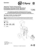
Install
Strain Relief
Cable Assembly
Black Cable
Cable Assembly
Red or White Cable
Motor Type 1
Install
Strain Relief
Cable Assembly
Black Cable
Cable Assembly
Red or White Cable
Motor Type 2
CAUTION
Disconnect electric and/or hydraulic power
and tag out if required before servicing or
performing maintenance.
CAUTION
Read this document before installing the
service motor kit.
CAUTION
Use standard methods and practices when
attaching spreader and installing accessories
including proper personal protective safety
equipment.
79065,
95755-2

79065, 95755-2
Lit. No. 96104, Rev. 02 2 November 15, 2012
The company reserves the right under its product improvement policy to change construction or design details and furnish equipment when
so altered without reference to illustrations or specifi cations used. This equipment manufacturer or the vehicle manufacturer may require or
recommend optional equipment for spreaders. Do not exceed vehicle ratings with a spreader. The company offers a limited warranty for all
spreaders and accessories. See separately printed page for this important information.
Printed in U.S.A.
5. Install the second rubber washer on the strain
relief inside the housing. Install the mounting nut
and securely tighten while holding the strain relief
to prevent turning.
6. Install the two-position cable bushing
and clamping nut onto the two
cables. Cutting the bushing in
the two locations shown will
aid in the installation.
7. Pass the two cables through the strain relief and
into the terminal housing. It may be necessary to
pass one cable at a time through the strain relief.
8. Connect the cables to the motor terminals. The
black cable will connect to the terminal furthest
from the the cable entry point. The red or white
cable will connect to the terminal closest to the
cable entry point.
Clamping Nut
Rubber
Washers
Strain Relief
Mounting Nut
Two-Position Cable Bushing
Cable Strain Relief
Motor Terminal
Cover Housing
9. Make sure that the ring terminals are not touching
one another or the motor case after being
tightened.
10. Install the motor terminal cover and both gaskets
and tighten with the four supplied screws removed
earlier.
11. Tighten the clamping nut, locking the cable in
place.
Cable Assembly
Black Cable
Cable Assembly
Red or White Cable
Cut both
sides
/