Page is loading ...

March 24, 2005 1 Manual 0-4671
Manual 0-4671
NASSCO MIJIT 1000
Wire Harness Replacement Kit
Catalog # 831059
Installation Instructions
© 2005 by Thermadyne Corp.,
82 Benning Street
West Lebanon, New Hampshire, USA 03784
(603) 298-5711
1
2
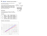
3 Multi-Conductor Cables
NOTE: These cables will be wrapped together
with tape for shipping and installation.
Art # A-04616
Figure 1: Supplied Parts
Item # Description Qty Part Number
1Wire Harness Assemb ly 1 870468
2 Locknut, steel, 1-inch 1 870467-100
not shown Wire Ties 4
not shown Instruction Manual 1 300x4671
Recommended Tools
(Note: wrench and socket sizes may vary.)
• Medium size flat-blade screwdriver
• Medium size Phillips screwdriver
• 1/4, 5/16, 3/8, 9/16-inch nutdrivers or sockets
• Ratchet wrench
• Slip-joint or channel-lock pliers
General Information
This field installable repair kit is intended to replace a
damaged or defective wire harness in a NASSCO Mijit
1000. This is a directly connected type of wire harness as
featured in the latter model Mijit 1000's or in older units
that have been upgraded from the 19-pin amphenol socket
/ printed circuit board type of wire harness.
Refer to rework kit number 870469 for the upgrade that
changes the amphenol socket/printed circuit board type of
wire harness into a directly connected type of wire harness.
Supplied Parts
The following components are included in this kit:

March 24, 2005 2 Manual 0-4671
Installation Procedure
CAUTION
Only a qualified technician should perform this pro-
cedure. Disconnect all input lines.
A. Dis-assemble The Enclosure
1. Turn the power source and MIJIT 1000 power
switches OFF. Disconnect all input lines. Unlatch
the outside cover and lay the MIJIT 1000 on its
side.
2. Remove the wire spool hub by removing the wire
spool hub nut and hub tension bolt with a 9/16-
inch socket. Refer to Figure 2 for location.
3. Remove the 5 screws (A - E) shown in Figure 2 to
detach the sheet metal door panels.
Wire Spool
Hub Nut
Hub Ten sion Bolt
:
:
4
4
0
0
9
9
4
4
4
4
6
6
A
C
DE
Art # A-04637
B
Plastic Caps
Hour Meter
Figure 2: Panel Screw And Hub Locations
4. Remove the 2 screws (F - G) shown in Figure 2 to
detach the wire harness entry hole cover panel.
5. Remove panels and hardware and set aside for re-
assembly.
+-
Wire # 4 Wire # 5
Meter Terminals
Hour Meter Harness
Art # A-04617
Figure 3: Disconnect Hour Meter (if present)
6. Disconnect the two wires from the rear of the hour
meter (if so equipped). Note the polarity and mark or
tape the positive wire for re-assembly. Refer to
Figure 3.
NOTE
The hour meter is a recent upgrade to the NASSCO
MIJIT 1000. Order catalog number 870540 to ob-
tain the upgrade kit

March 24, 2005 3 Manual 0-4671
B. Remove The Three Twist-Loc Connectors
1. Separate the rubber boot from each Twist-Loc con-
nector with a small flat blade screwdriver. Note
the location of the two cable strain relief screws.
Refer to Figure 4.
Twi st-Loc Connector (3)
Rubber Boot (3)
Strain Relief Screw (2 each)
Art # A-04618
Figure 4: Separate Rubber Boots
2. Loosen the two screws until the strain relief no
longer grips the cable. It is not necessary to remove
the screws or the strain relief. Refer to Figure 5.
Strain Relief
Strain Relief Screw (2)
Strain Relief Screw Head (2)
Art # A-04619
Figure 5: Loosen Strain Relief Screws
3. Separate the two halves of each connector by back-
ing off the front screws by a full turn. These screws
are captive and will remain in the front half of the
connector. Note that the black connectors contain
two front screws and the yellow connector con-
tains three (as shown). Refer to Figure 6.
Captive Screw (2 or 3 per connector)
Twi st-Loc Half
Outside Half
Locater
Key
Art # A-04620
Figure 6: Separate Connector Halves
4. Loosen the conductor screws just enough until the
conductor wires can be removed from the connec-
tor. Refer to Figure 7.
NOTE
Take note and write down the terminal letters and
their respective wire colors before disconnecting the
wires. Verify your information with the Twist-Loc
Connector Wiring Table on page 13.
5. Pull off the outside connector half and the rubber
boot from each cable. Place these component with
their Twist-Loc connector halves for re-assembly.
Conductor Screw
(3 to 5 per connector)
Art # A-04621
Figure 7: Loosen Conductor Screws

March 24, 2005 4 Manual 0-4671
C. Dis-assemble the Wire Harness
1. Remove the plastic bushing from the threaded
strain relief where it enters the inside of the case.
Channel-lock pliers may be needed to do this. Re-
fer to Figure 8.
Plastic Bushing
Threaded Strain Relief
Art # A-04622
1-Inch Locknut
Figure 8: Remove Plastic Bushing
2. Remove the 1-inch locknut from the threaded strain
relief. The locknut is easily loosened by using your
left hand to slightly rotate the knurled retainer/
threaded strain relief assembly counter-clockwise
on the outside of the case while holding the lock-
nut with your right hand. Refer to Figures 8 and 9.
Art # A-04623
1-Inch Locknut (inside)
Knurled Retainer
And Threaded Strain
Relief Assembly
Figure 9: Remove 1-inch Locknut
3. Remove the knurled retainer from the threaded
strain relief assembly using channel-lock pliers.
Refer to Figure 10.
Knurled RetainerThreaded Strain Relief
Art # A-04624
Figure 10: Remove Knurled Retainer
4. Pull the rubber compression bushing out of the
strain relief assembly using pliers or a flat-blade
screwdriver. Refer to Figure 11.
Rubber Compression Bushing
Art # A-04625
Figure 11: Pull Out Compression Bushing

March 24, 2005 5 Manual 0-4671
5. Snip and remove the wire tie from the 3 multi-con-
ductor cables at end of the mesh strain relief cord
grip. Refer to Figure 12.
Mesh Strain Relief Cord Grip
Multi-Conductor Cables
Wire Tie
Art # A-04626
Figure 12: Snip And Remove Wire Tie
6. Compress the mesh strain relief cord grip to in-
crease the diameter of the mesh. Refer to Figure 13.
Art # A-04627
Figure 13: Compress Mesh Cord Grip
Knurled Retainer
Rubber Compression Bushing
Threaded Strain Relief
Mesh Strain Relief Cord Grip
Multi-Conductor Cables
Art # A-04628
Figure 14: Pull The Cables Through The
Components
7. Pull each of the 3 multi-conductor cables through
the knurled retainer, the mesh strain relief cord
grip, the rubber compression bushing and the
threaded strain relief assembly. Refer to Figure 14.
Do not pull the cables through the hole in the MIJIT
1000 housing until the wire harness is discon-
nected from the inside as defined in the next step.

March 24, 2005 6 Manual 0-4671
D. Disconnect And Remove The Wire Harness
From The Inside
1. Remove the chassis grounding stud nut and brass
washer using an 11/32-inch nut driver or socket
and ratchet and set aside for re-assembly. Pull the
green-yellow wire with the ring-lug terminal off
the grounding stud. Refer to Figure 15.
Chassis Grounding Stud Nut
Green-Yellow Wire With Ring-Lug Terminal
Art # A-04545
Figure 15: Remove Chassis Grounding Stud Nut
And Green-Yellow Wire
2. Disconnect the two insulated quick-connectors
from the F1 fuse located behind the fuse panel.
Refer to Figure 16.
Art # A-04546
F1 Fuse located behind panel here
Upper Fuse Connector Lower Fuse Connector
Figure 16: Disconnect The Two F1 Fuse Wires

March 24, 2005 7 Manual 0-4671
3. Disconnect the J2 Molex connector from the motor
control board. Refer to Figure 17.
CAUTION
The J2 Molex connector and/or the insulated quick
connectors may catch on and potentially damage
components in the machine when removing the wire
harness.
J2 Connector
Art # A-04547
Motor Control
Board
Figure 17: Disconnect J2 Molex Connector From
Motor Control Board.
J2 Socket
Art # A-04565
Vertical Frame Base
J2 Molex Connector
Wire Harness
Art # A-04566
Figure 19: Wire Harness Pulled Around Bottom Of
Vertical Frame
6. Pull each of the 3 multi-conductor cables through
the hole in the housing and remove the wire har-
ness from the case.
4. Pull the J2 Molex connector down along the right
side of the vertical frame down to the base of the
enclosure. Clip and remove wire ties as necessary.
Refer to Figure 18.
Figure 18: Pull Wire Harness Down Along Frame
5. Pull the J2 Molex connector around the back of the
vertical frame member at its base. Refer to Figure 19.

March 24, 2005 8 Manual 0-4671
E. Route The New Wire Harness Into The Case
1. Carefully compress the J2 Molex connector and its
wires and pass it through the wire harness entry
hole. Pull the two loose wires through the hole as
well. Refer to Figure 20.
Art # A-04550
J2 Molex Connector
Figure 20: Pass J2 Molex Connector And Wires
Through Hole
2. Carefully compress the J2 Molex connector and its
wires and pass it through the NEW 1-inch locknut
(supplied). Pull the two loose wires through the
locknut as well. Refer to Figure 21.
1-inch Locknut
Art # A-04551
Figure 21: Pass J2 Molex Connector And Wires
Through Locknut
CAUTION
Do not re-use the old 1-inch locknut.

March 24, 2005 9 Manual 0-4671
Figure 23: Wire Harness Pulled Up Along Frame
3. Slide the locknut down the harness to the entry
hole and do not let it get pulled around the back of
the vertical frame member. Lead the J2 Molex con-
nector around the back of the vertical frame mem-
ber at its base. Refer to Figure 22.
Vertical Frame Base
Locknut J2 Molex Connector
Wire Harness
Art # A-04552
Figure 22: Wire Harness Routed Around Bottom
Of Vertical Frame
4. Pull the J2 Molex connector up along the right side
of the vertical frame to where it is level with the J2
socket on the motor control board. Refer to Figure 23.
J2 SocketWire Harness Route
Art # A-04553

March 24, 2005 10 Manual 0-4671
F. Connect The New Wire Harness
1. Put the Ground Fault Printed Circuit Board and
its associated green/yellow ground wire under the
vertical frame member from right (Motor Control
Printed Circuit Board side) to left (chassis ground
stud side). Refer to Figure 24.
Ground Fault Printed Circuit Board
Art # A-04554
Wire Tie Here J4 Connector
Figure 24: Route Harness Under Vertical Frame
2. Install the ring lug terminal from the green/yel-
low ground wire to the chassis ground stud. Re-
install the nut that was previously removed on to
chassis ground stud. Refer to Figures 25 and 27.
Chassis Grounding Stud Nut
Green-Yellow Wire With Ring-Lug Terminal
Art # A-04545
Figure 25: Replace Chassis Grounding Stud Nut
And Green-Yellow Wire
3. Using a supplied wire tie, secure the Ground Fault
Printed Circuit Board assembly to the wire har-
ness leading to the J4 connector on the Motor Con-
trol Printed Circuit Board. Replace any other wire
ties that may have been removed. Refer to Figure 24.
4. Connect the J2 Molex connector to Motor Con-
trol Printed Circuit Board. This connector is
keyed so that it can not be installed incorrectly.
NOTE
The latching/locating ridge that runs along the
length of the J2 Molex connector will be on the left-
hand side when facing the board socket. Refer to
Figures 24, 26 and 27.
J2 Molex Connector
Latching/Locator Ridge On Left
Art # A-04556
Wire #1
Figure 26: Plug J2 Molex Connector Back Into Board

March 24, 2005 11 Manual 0-4671
Art # A-04546
F1 Fuse located behind panel here
Upper Fuse Connector Lower Fuse Connector
Figure 27: Loose Wire Connections
+-
Wire # 4 Wire # 5
Meter Terminals
Meter harness looped
around rear of post
Art # A-04630
6. Route the other single spade terminal wire from
the harness around the top of the Motor Control
Printed Circuit Board and connect it to the lower
spade terminal on the back side of fuse F1. Refer to
Figures 27 and 28.
Figure 29: Reconnect Hour Meter (if so equipped)
5. Route wire number 1 from the J2 Molex connector
around the top of the Motor Control Printed Cir-
cuit Board and connect it to the upper spade termi-
nal on the back side of fuse F1. Refer to Figures 26,
27 and 28.
Wire # 1: Connect to upper spade
terminal on back side of fuse F1
Connect this wire to the lower spade terminal on the back side of fuse F1
Ground Wire: Attach to chassis ground stud
Art # A-04629
Hour Meter Wires (wire connected to #4 is positive)
J2 Molex Connector
Figure 28: Re-Connect The Two F1 Fuse Wires
7. Connect the two paired wires to the rear of the
hour meter (if so equipped). Note that the hour
meter's positive (+) terminal connects to the wire
that is spliced to the #4 wire in the J2 Molex con-
nector. Refer to Figures 27 and 29.

March 24, 2005 12 Manual 0-4671
8. Take the threaded strain relief (located on the wire
harness outside of the case), slide it down the har-
ness and insert it into the wire harness entry hole.
Refer to Figure 30. Note that the mesh strain relief
cord grip will need to be compressed to do this as
explained in Section C, step 6.
Threaded Strain Relief
Art # A-04631
Figure 30: Insert Strain Relief Into Wire Harness
Entry Hole
9. Thread the 1-inch locknut on to the strain relief and
tighten it securely with pliers while firmly grasping
the knurled retainer on the outside of the harness.
Refer to Figures 31 and 32.
1-Inch Locknut
Art # A-04632
Figure 31: Fasten Locknut To Strain Relief
Art # A-04555
Figure 32: Grasp Knurled Retainer While
Tightening Locknut

March 24, 2005 13 Manual 0-4671
G. Assemble The Three Twist-Loc Connectors
1. Remove the electrical tape that bundles the 3 multi-
conductor cables. Note that the multi-conductor
cables contain 3, 4, and 5 wires respectively.
2. Slide the yellow boot followed by its outside yel-
low connector half over the 3-wire cable. Repeat
this process with the black boots and their black
connector halves over the other two cables. Do
not tighten the strain relief screws yet. Refer to
Figure 33.
3 Wires 5 Wires
4 Wires
Rubber Boot (3)
Connector Half,
Black (2)
Connector
Half, Yellow
Art A-04633
Figure 33: Assemble Boots And Connector Halves
3. Connect each of the multi-cable's lead wires to the
conductor screws on the Twist-Loc connector half.
Refer to the wiring chart below and Figure 34.
NOTE
The black Twist-Loc connectors contain two front
screws and 4 or 5 conductor screws and the yellow
Twist-Loc connector contains three front screws.
Conductor Letter Wire Color
WRed
XGreen
YOrange
ZBlack
Center White
Conductor Letter Wire Color
WWhite
XBlack
YRed
ZGreen
Conductor Letter Wire Color
GR Green
WH White
Unmarked Black
Yellow Connector - 3 Wire
Black Connector - 5 Wire
Twist-Loc Connector Wirin
g
Black Connector - 4 Wire
Conductor Screw
(3 to 5 per connector)
Art # A-04634
Figure 34: Connect Wires To Conductor Screws

March 24, 2005 14 Manual 0-4671
4. Using the Locator Key as a guide, assemble the
two halves of each connector by tightening the front
captive screws by a full-turn. Refer to Figure 35.
Captive Screw (2 or 3 per connector)
Twi st-Loc Half
Outside Half
Locater
Key
Art # A-04635
Figure 35: Assemble Connector Halves
5. Tighten the two strain relief screws until the cable
is secure and will not slide under a reasonable
amount of tension. Refer to Figure 36.
Strain Relief
Strain Relief Screw (2)
Strain Relief Screw Head (2)
Art # A-04619
Figure 36: Tighten Strain Relief Screws
6. Slide the 3 boots on to the back of the 3 connectors
and snap them into place.

March 24, 2005 15 Manual 0-4671
G. Re-assemble The Mijit 1000
Reverse the steps in Section A. Refer to Figure 37.
1. Place the sheet metal door panels back in position
and install the 5 screws (A - E) to attach.
2. Place the wire harness entry hole cover panel in
position and install the 2 screws (F - G) to attach.
3. Replace the wire spool hub and install the wire spool
hub nut and hub tension bolt with a 9/16-inch
socket.
Wire Spool
Hub Nut
Hub Ten sion Bolt
:
:
4
4
0
0
9
9
4
4
4
4
6
6
A
C
DE
Art # A-04637
B
Plastic Caps
Hour Meter
Figure 37: Re-Assemble The Mijit 1000
Art # A-04638
Figure 38: Rear Panel With Wire Harness Installed
NOTE
Every effort has been made to provide complete and
accurate information in this manual. However, the
publisher does not assume and hereby disclaims any
liability to any party for any loss or damage caused
by errors or omissions in this manual, whether such
errors result from negligence, accident or any other
cause.

March 24, 2005 16 Manual 0-4671
MIJIT 1000 SCHEMATIC DIAGRAM
FEED MONITOR DRIVER
12 VDC
COM.
NOT USED
REMOTE VOLT MAX.
REMOTE VOLT REF.
REMOTE VOLT MIN.
LED METER SELECT
LED METER SELECT
V/!W
WFS MAX.
WFS REF
WFS MIN.
2/4 STEP ENABLE
2/4 STEP ENABLE
MET/!ENG
5 VDC
COM.
ASSEMBLY
DISPLAY BOARD
DP COM.
DP SELECT
(-) INPUT
(+) INPUT
1
2
4
5
7
8
6
3
9
J8
10
6
13
14
15
12
16
11
10
7
8
9
(INCH)
J1
2
3
1
4
5
S2
(PURGE)
S2
MOTOR CONTROL BOARD ASSEMBLY
OPEN
LEGEND
S1
T1
S2
L1
J1
B1
J7
6
13
14
15
16
7
9
10
12
11
8
J1
10
9
J1
1
2
3
4
5
6
5
4
J5
3
2
1
3
DP COM.
(+) INPUT
(-) INPUT
DP SELECT
6
8
7
J3
5
4
COM.
5 VDC
2
1
12 3
10
9
8
7
6
4
5
1
2
3
SWITCH, OFF/ON, CIRCUIT BREAKER
MOTOR, WIRE FEED
RECEPTACLE, GUN SWITCH
GAS VALVE, 24 VAC
SWITCH, INCH/PURGE
TRANSFORMER, CONTROL
54
F1 FUSE, 1 AMP AGC
A
B
D
C
65
F
E
78
78 56
Art # A-04481

March 24, 2005 17 Manual 0-4671
17V LO (1)
17V LO (3)
17V HI (3)
16
15
13V HI
17V HI (1)
8V LO
12
13
14 11
10 5
24V HI
8V HI
13V LO
24V LO
17V LO (2)
9
J4
86
7
120V LO
120V HI
17V HI (2)
T1
J2
4
3
3
2
2
1
1
5
4
6
7
8
9
10
3
11
13
12
15
14
1
2
J6
8
7
5
4
6
120 VAC HI
REMOTE VOLT MAX.
REMOTE VOLT REF.
CONTACTOR IN
CONTACTOR OUT
REMOTE VOLT MIN.
PS COM.
ARC EST. IN
120 VAC LO
GND FAULT DETECT
GND FAULT DETECT
B1
+
L1
2
S1
1
V ARC -
I/F SELECT
V ARC +
F1
Refer to wiring diagram
charts below for version.
+
_
HOUR METER
DIAGRAM, CONNECTION & SCHEMATIC
MIJIT 1000
800001: NONE
1 OF 2
FULLATC DBB 8-4-99
870197S1 9-6-00
ATC ATC 9-27-99
130
TECH PUB
870197-2
PLOT DATE
CHECKED APPROVED RECORDS ITEM TYPE
DESIGNED DRAWN DATE SCALE
COMM. CLS.
DESCRIPTIVE DATA
TITLE
MATERIAL SPEC.
MATERIAL NO.
ACTIVITY
FINISH CODE PER
REPLACED BY REPLACES
QUANTITY-U.M.
DWG. NO.SIZE
C
FRACT.
INCH
±
SHEET
1234
DISTRIBUTION TABLE
OUTSIDE DISTR.
A
B
C
D
E
F
4 3 21
CONFIDENTIAL: This drawing, including all information
contained thereon, is the exclusive and confidential property of
Thermal Arc Corporation of Troy, Ohio 45373 . This drawing is
not to be copied, reproduced, delivered or disclosed to others,
in whole or in part, except with express written permission.
TROY, OHIO 45373, U.S.A.
ANGLES
± 3˚
UNLESS OTHERWISE SPECIFIED
DIMENSIONS ARE IN INCHES/MILLIMETERS
TOLERANCES BELOW APPLY EXCEPT FOR
VENDOR DESIGNED PARTS AND ITEMS.
PRODUCED TO RECOGNIZED STANDARDS.
DECIMAL-INCH
0.00 ± 0.1mm
0.0 ± 0.4mm
0. ± 1.0mm
.000 ± .003
.00 ± .02
DO NOT SCALE DRAWING
.0 ± .1
A THERMADYNE Company
d
FILE NAME
Art # A-04481

March 24, 2005 18 Manual 0-4671
MIJIT 1000 CONNECTION DIAGRAM
NOTES:
1. RUN-IN SPEED TIME CONFIGURATION
2. UNITS ARE TO BE SHIPPED IN THE 0.2 SEC
RUN-IN CONFIGURATION.
3. LEAVE TAPE ON J7.
4. USING WIRE TIES, ROUTE WIRES AS TO AVOID
CONTACT WITH MOTOR.
MOTOR CONTROL BOARD ASSEMBLY
OPEN
45231
8
(T) BRN-WHT
(T) BLU-WHT
(T) ORN
(T) ORN-WHT
(T) YEL
(T) YEL-WHT
(T) BLK
15
15
15
15
15
15
15
7
1
5
3
13
11
9
15
J4
15
15
(T) BRN
(T) BLUE
(T) GRAY-WHT
15
15
(T) GRAY
(T) RED
(T) RED-WHT
(T) BLK-WHT
15
15
15
15
11
13
14
12
J2
9
10
7
8
17
17
5
3
4
2
1
17
17
17
KEY
6
7
17
17
17
8
5
6
3
4
1
2
J6
6
7
5
4
3
2
1
6
22 BLK
35
36
37
9
17
17
17
17
29
30
17
4A
26 BRN
25 ORN
23 BLK
6
16
16
27 BLK
28 RED
3
3
4
2
8
6
10
12
14
16
11
11
11
11
11
11
11
11
11
11
11
11
(T) BLK-WH
T1
(T) BLK
11
11
25 ORN
26 BRN
L1
13
13
FRAME GROUND
FACING WIRE SPOOL AY
(COMPONENTS OPPOSITE SIDE)
38 GRN-YEL
(T) RED
(T) BRN
(T) GRAY-WH
(T) BRN-WH
(T) GRAY
(T) RED-WH
(T) YEL
(T) BLU-WH
(T) BLU
(T) ORN
(T) ORN-WH
(T) YEL-WH
WIRE 38
WIRE 30
WIRE 29
11
12
13
15
16
14
- =NOT USED HERE
X=CLOSED
DISPLAY
IPM
MPM
WFS
METER
0.4 SEC
0.3 SEC
0.2 SEC
0.1 SEC
TIME
RUN IN
O
-
O=OPEN
-- -
54321
-
3
POSITION
DIP SWITCH
O
0
O
X
-
1
-
2
O
X
O
0
O
O
X
O
X
5
-
4
-
-
-
-
-
-
-
-
DIP SWITCH
POSITION
SEE NOTES 1 & 2
11 10 9 8 7
789101112
A
B
C
D
E
F
G
H
Art # A-04199

March 24, 2005 19 Manual 0-4671
12 ORN
13 BLU
14 BRN
15 WHT
J8
1
10 RED
11 BLK
10
10
10
10
10
10
J1
ASSEMBLY
DISPLAY BOARD
GROUND STUD
FRONT PANEL
1
1
14 BRN
15 WHT
2
1
4
3
5
1
1
1
1
11 BLK
12 ORN
13 BLU
10 RED
7
6
8
J3
10
9
J1
J7
6
5
4
4
4
4
5
1
J5
4
3
2
5
19 YEL
17 WHT
18 RED
16 BRN
21 0RN
20 BLU
B1
28 RED
27 BLK
13
13
(M) BLK
(M) RED
S1
LINE
12(K)
11
13
13
23 BLK
22 BLK
18 RED
S2
8
8
8
19 YEL
17 WHT
16 BRN
8
J1
21 ORN
20 BLU
8
8
2435678109
38 GRN-YEL
FACING REAR OF CONTROL PANEL
FACING REAR OF FEEDHEAD PANEL
FACING INTERIOR PANEL
12
17
1 RED
39 RED
F1
SUPPLIED W/ METER PC BOARD
J9
J10
J10 J9
1
2
10
9
8
7
6
3
4
5
4A
DIAGRAM, CONNECTION & SCHEMATIC
MIJIT 1000
800001: NONE
2
FULLATC DBB 8-4-99
870197S2 9-22-03
ATC ATC 9-27-99
130
TECH PUB
870197
SEE NOTE 3
SEE NOTE 4
CHANGE RECORD
E.C. No. DATE
PLOT DATE
CHECKED APPROVED RECORDS ITEM TYPE
DESIGNED DRAWN DATE SCALE
COMM. CLS.
DESCRIPTIVE DATA
TITLE
MATERIAL SPEC.
MATERIAL NO.
ACTIVITY
FINISH CODE PER
REPLACED BY REPLACES
QUANTITY-U.M.
DWG. NO.SIZE
D
FRACT.
INCH
±
SHEET
FILE NAME
DISTRIBUTION TABLE
OUTSIDE DISTR.
654321
456 123
H
G
F
E
D
C
B
A
CONFIDENTIAL: This drawing, including all information con-
tained thereon, is the exclusive and confidential property of
Thermal Arc, Inc. of Troy, Ohio 45373 . This drawing is not
to be copied, reproduced, delivered or disclosed to others,
in whole or in part, except with express written permission.
TROY, OHIO 45373 , U.S.A.
ANGLES
± 3˚
UNLESS OTHERWISE SPECIFIED
DIMENSIONS ARE IN INCHES/MILLIMETERS
TOLERANCES BELOW APPLY EXCEPT FOR
VENDOR DESIGNED PARTS AND ITEMS.
PRODUCED TO RECOGNIZED STANDARDS.
DECIMAL-INCH
METRIC
0.00 ± 0.1mm
0.0 ± 0.4mm
0. ± 1.0mm
.000 ± .003
.00 ± .02
DO NOT SCALE DRAWING
.0 ± .1
A THERMADYNE Company
R
R
Art # A-04199
/