1
THE SERVSWITCH FAMILY
Welco me to the ServSw itch
TM
Fam ily!
Thank you for purchasing a BLACK BOX
®
ServSwitch
™
Brand KVM switch! We appreciate
your business, and we think you’ll appreciate the many ways that your new ServSwitch
keyboard/video/mouse switch will save you money, time, and effort.
That’s because our ServSwitch family is all about breaking away from the traditional,
expensive model of computer management. You know, the one-size-fits-all-even-if-it-doesn’t
model that says, “One computer gets one user station, no more, no less.” Why not a single
user station (monitor, keyboard, and mouse) for multiple computers—even computers of
different platforms? Why not a pair of user stations, each of which can control multiple
computers? Why not multiple user stations for the same computer?
With our ServSwitch products, there’s no reason why not. We carry a broad line of robust
solutions for all these applications. Do you have just two PCs, and need an economical
alternative to keeping two monitors, keyboards, and mice on your desk? Or do you need to
share dozens of computers, including a mix of IBM
®
PC, RS/6000
®
, Apple
®
Macintosh
®
, Sun
Microsystems
®
, and SGI
®
compatibles, among multiple users with different access levels? Does
your switch have to sit solidly on a worktable and use relatively inexpensive cables? Or does it
have to be mounted in an equipment rack and use convenient many-to-one cables? No
matter how large or small your setup is, no matter how simple or how complex, we’re
confident we have a ServSwitch system that’s just right for you.
The ServSwitch
™
family from Black Box—the one-stop answer for all your KVM-switching
needs!
*
This manual will tell you all about your “-R2” ServSwitch, including how to install, operate,
and troubleshoot it.

2
“R2” SERVSWITCH
TRADEMARKS USED IN THIS MANUAL
AT, IBM, PS/2, and ThinkPad are registered trademarks, and PC/XT is a
trademark, of International Business Machines Corporation.
Logitech is a registered trademark of Logitech, Inc.
Microsoft and Windows are either registered trademarks or trademarks of
Microsoft Corporation in the United States and/or other countries.
Any other trademarks mentioned in this manual are acknowledged to be the property of the
trademark owners.

3
FCC AND IC RFI STATEMENTS
FEDERAL COMMUNICATIONS COMMISSION
AND
INDUSTRY CANADA
RADIO FREQUENCY INTERFERENCE STATEMENTS
This equipment generates, uses, and can radiate radio-frequency energy, and if not
installed and used properly, that is, in strict accordance with the manufacturer’s
instructions, may cause interference to radio communication. It has been tested
and found to comply with the limits for a Class A computing device in accordance
with the specifications in Subpart B of Part 15 of FCC rules, which are designed to
provide reasonable protection against such interference when the equipment is
operated in a commercial environment. Operation of this equipment in a
residential area is likely to cause interference, in which case the user at his own
expense will be required to take whatever measures may be necessary to correct
the interference.
Changes or modifications not expressly approved by the party responsible
for compliance could void the user’s authority to operate the equipment.
This digital apparatus does not exceed the Class A limits for radio noise emission from
digital apparatus set out in the Radio Interference Regulation of Industry Canada.
Le présent appareil numérique n’émet pas de bruits radioélectriques dépassant les limites
applicables aux appareils numériques de la classe A prescrites dans le Règlement sur le
brouillage radioélectrique publié par Industrie Canada.

4
“R2” SERVSWITCH
NORMAS OFICIALES MEXICANAS (NOM)
ELECTRICAL SAFETY STATEMENT
INSTRUCCIONES DE SEGURIDAD
1. Todas las instrucciones de seguridad y operación deberán ser leídas antes de
que el aparato eléctrico sea operado.
2. Las instrucciones de seguridad y operación deberán ser guardadas para
referencia futura.
3. Todas las advertencias en el aparato eléctrico y en sus instrucciones de
operación deben ser respetadas.
4. Todas las instrucciones de operación y uso deben ser seguidas.
5. El aparato eléctrico no deberá ser usado cerca del agua—por ejemplo, cerca
de la tina de baño, lavabo, sótano mojado o cerca de una alberca, etc..
6. El aparato eléctrico debe ser usado únicamente con carritos o pedestales que
sean recomendados por el fabricante.
7. El aparato eléctrico debe ser montado a la pared o al techo sólo como sea
recomendado por el fabricante.
8. Servicio—El usuario no debe intentar dar servicio al equipo eléctrico más allá
a lo descrito en las instrucciones de operación. Todo otro servicio deberá ser
referido a personal de servicio calificado.
9. El aparato eléctrico debe ser situado de tal manera que su posición no
interfiera su uso. La colocación del aparato eléctrico sobre una cama, sofá,
alfombra o superficie similar puede bloquea la ventilación, no se debe colocar
en libreros o gabinetes que impidan el flujo de aire por los orificios de
ventilación.
10. El equipo eléctrico deber ser situado fuera del alcance de fuentes de calor
como radiadores, registros de calor, estufas u otros aparatos (incluyendo
amplificadores) que producen calor.
11. El aparato eléctrico deberá ser connectado a una fuente de poder sólo del
tipo descrito en el instructivo de operación, o como se indique en el aparato.

5
NOM STATEMENT
12. Precaución debe ser tomada de tal manera que la tierra fisica y la polarización
del equipo no sea eliminada.
13. Los cables de la fuente de poder deben ser guiados de tal manera que no
sean pisados ni pellizcados por objetos colocados sobre o contra ellos,
poniendo particular atención a los contactos y receptáculos donde salen del
aparato.
14. El equipo eléctrico debe ser limpiado únicamente de acuerdo a las
recomendaciones del fabricante.
15. En caso de existir, una antena externa deberá ser localizada lejos de las lineas
de energia.
16. El cable de corriente deberá ser desconectado del cuando el equipo no sea
usado por un largo periodo de tiempo.
17. Cuidado debe ser tomado de tal manera que objectos liquidos no sean
derramados sobre la cubierta u orificios de ventilación.
18. Servicio por personal calificado deberá ser provisto cuando:
A: El cable de poder o el contacto ha sido dañado; u
B: Objectos han caído o líquido ha sido derramado dentro del aparato; o
C: El aparato ha sido expuesto a la lluvia; o
D: El aparato parece no operar normalmente o muestra un cambio en su
desempeño; o
E: El aparato ha sido tirado o su cubierta ha sido dañada.

6
“R2” SERVSWITCH
Contents
Chapter Page
1. Specifications . . . . . . . . . . . . . . . . . . . . . . . . . . . . . . . . . . . . . . . . . . . . . . . . . . 8
2. Introduction . . . . . . . . . . . . . . . . . . . . . . . . . . . . . . . . . . . . . . . . . . . . . . . . . . 10
2.1 The Complete Package . . . . . . . . . . . . . . . . . . . . . . . . . . . . . . . . . . . . . 10
2.2 Operating Features. . . . . . . . . . . . . . . . . . . . . . . . . . . . . . . . . . . . . . . . . 10
2.3 The Front Panel . . . . . . . . . . . . . . . . . . . . . . . . . . . . . . . . . . . . . . . . . . . 11
2.4 The Rear Panel . . . . . . . . . . . . . . . . . . . . . . . . . . . . . . . . . . . . . . . . . . . . 12
2.5 Cable Requirements . . . . . . . . . . . . . . . . . . . . . . . . . . . . . . . . . . . . . . . . 14
3. Installation . . . . . . . . . . . . . . . . . . . . . . . . . . . . . . . . . . . . . . . . . . . . . . . . . . . 15
3.1 Quick Setup Guide . . . . . . . . . . . . . . . . . . . . . . . . . . . . . . . . . . . . . . . . . 15
3.2 Installation Procedure . . . . . . . . . . . . . . . . . . . . . . . . . . . . . . . . . . . . . . 16
3.2.1 Rackmounting (Optional) . . . . . . . . . . . . . . . . . . . . . . . . . . . . . 16
3.2.2 Connecting the Monitor, Keyboard, and Mouse . . . . . . . . . . . 16
3.2.3 Connecting CPUs . . . . . . . . . . . . . . . . . . . . . . . . . . . . . . . . . . . . 16
3.2.4 Powering Up the System . . . . . . . . . . . . . . . . . . . . . . . . . . . . . . . 17
3.2.6 Switching from the Keyboard. . . . . . . . . . . . . . . . . . . . . . . . . . . 18
4. Operation . . . . . . . . . . . . . . . . . . . . . . . . . . . . . . . . . . . . . . . . . . . . . . . . . . . 19
4.1 Guidelines for Using the ServSwitch with Your Equipment . . . . . . . . 19
4.1.1 CPUs. . . . . . . . . . . . . . . . . . . . . . . . . . . . . . . . . . . . . . . . . . . . . . . 19
4.1.2 Mouse and Keyboard. . . . . . . . . . . . . . . . . . . . . . . . . . . . . . . . . . 19
4.1.3 Monitor . . . . . . . . . . . . . . . . . . . . . . . . . . . . . . . . . . . . . . . . . . . . 20
4.2 Keyboard Command Summary . . . . . . . . . . . . . . . . . . . . . . . . . . . . . . . 22
4.3 The Commands in Detail. . . . . . . . . . . . . . . . . . . . . . . . . . . . . . . . . . . . 25
4.3.1 Selecting a Port from the Shared Keyboard . . . . . . . . . . . . . . . 25
4.3.2 Switching to the Next or Previous Port . . . . . . . . . . . . . . . . . . . 25
4.3.3 Scan Mode . . . . . . . . . . . . . . . . . . . . . . . . . . . . . . . . . . . . . . . . . . 25
4.3.4 Keep Settings . . . . . . . . . . . . . . . . . . . . . . . . . . . . . . . . . . . . . . . . 26
4.3.5 Set Scan-Delay Time . . . . . . . . . . . . . . . . . . . . . . . . . . . . . . . . . . 26
4.3.6 Set Screen-Saver Interval. . . . . . . . . . . . . . . . . . . . . . . . . . . . . . . 26
4.3.7 Set Keyboard Mode . . . . . . . . . . . . . . . . . . . . . . . . . . . . . . . . . . . 27
4.3.8 Set Keyboard Typematic . . . . . . . . . . . . . . . . . . . . . . . . . . . . . . . 28
4.3.9 Reset . . . . . . . . . . . . . . . . . . . . . . . . . . . . . . . . . . . . . . . . . . . . . . . 30
4.3.10 Send Null Byte . . . . . . . . . . . . . . . . . . . . . . . . . . . . . . . . . . . . . . . 30
4.3.11 Identify ROM . . . . . . . . . . . . . . . . . . . . . . . . . . . . . . . . . . . . . . . . 31
4.4 Using the RS-232 Port (Optional). . . . . . . . . . . . . . . . . . . . . . . . . . . . . 31

7
CONTENTS
Chapter Page
5. Troubleshooting . . . . . . . . . . . . . . . . . . . . . . . . . . . . . . . . . . . . . . . . . . . . . . 32
5.1 Diagnostic Information . . . . . . . . . . . . . . . . . . . . . . . . . . . . . . . . . . . . . 32
5.2 Restoring Factory-Default Settings . . . . . . . . . . . . . . . . . . . . . . . . . . . . 33
5.3 Common Problems. . . . . . . . . . . . . . . . . . . . . . . . . . . . . . . . . . . . . . . . . 33
5.3.1 A CPU Connected to Your ServSwitch Doesn’t Boot,
and You Get a Keyboard or Mouse Error . . . . . . . . . . . . . . . . . 33
5.3.2 You Can’t Switch Ports from the Keyboard . . . . . . . . . . . . . . . . 34
5.3.3 Characters that You Type Come Up Wrong or Missing . . . . . . 35
5.3.4 Your Mouse Driver Doesn’t Load. . . . . . . . . . . . . . . . . . . . . . . . 35
5.3.5 You Can’t Access All the Functions of Your Mouse . . . . . . . . . 35
5.3.6 Your PS/2 Mouse Gets Out of Sync . . . . . . . . . . . . . . . . . . . . . . 36
5.3.7 Your Mouse Doesn’t Move the Pointer/Cursor . . . . . . . . . . . . 36
5.3.8 Your Monitor Display is Fuzzy . . . . . . . . . . . . . . . . . . . . . . . . . . 36
5.3.9 Your Video is Not Synchronized or is the Wrong Color. . . . . . 36
5.3.10 Your Video is OK in Low-Resolution Mode, But You Can’t
Get Into High-Resolution Mode. . . . . . . . . . . . . . . . . . . . . . . . . 37
5.3.11 You Can’t Seem to Scan or Switch to One or More
of Your CPUs . . . . . . . . . . . . . . . . . . . . . . . . . . . . . . . . . . . . . . . . 37
5.3.12 The ServSwitch Doesn’t Work with Your Docking Station. . . . 37
5.3.13 The ServSwitch Doesn’t Work with Your
Dongle-Protected Software . . . . . . . . . . . . . . . . . . . . . . . . . . . . . 37
5.4 Calling Black Box . . . . . . . . . . . . . . . . . . . . . . . . . . . . . . . . . . . . . . . . . . 37
5.5 Shipping and Packaging. . . . . . . . . . . . . . . . . . . . . . . . . . . . . . . . . . . . . 38
Appendix A. NVRAM Factory Defaults . . . . . . . . . . . . . . . . . . . . . . . . . . . . . . . . 39
Appendix B. Cable Product Codes. . . . . . . . . . . . . . . . . . . . . . . . . . . . . . . . . . . . 40
Appendix C. Pinout of RS-232 Port . . . . . . . . . . . . . . . . . . . . . . . . . . . . . . . . . . . 42

8
“R2” SERVSWITCH
1. Speci fications
Compliance: FCC Class A, DOC Class/MDC classe A
Standards:
With original Serv cabling: VGA (color, monochrome, or page white),
EGA (color or monochrome), or CGA video;
With original Serv cabling (minimal) or coaxial cabling (recommended):
SVGA video;
With coaxial cabling: XGA (color or monochrome) video;
With special cabling: True monochrome video
Interfaces: CPU and MONITOR/KEYBOARD/MOUSE Ports:
Proprietary composite of IBM PS/2 keyboard, PS/2 mouse, and video
(standards listed above);
RS-232 Port: Proprietary variant of EIA RS-232D using 6-wire RJ-11 connectors,
DTE
Resolution: With original Serv cabling: Up to 1024 x 768;
With coaxial or special cabling: Up to 1280 x 1024
Protocols: RS-232: Asynchronous
Data Formats: RS-232: 8 data bits, 1 stop bit, no parity
Speed: RS-232: 9600 bps
Maximum Distance: Depending on the CPU, monitor, and video resolution
(see Section 4.1.3), either:
25 ft. (7.6 m) of total original Serv cable from the keyboard, monitor,
and mouse to any CPU, including up to 5 ft. (1.5 m) from any
ServSwitch to any other Serv unit (submaster) attached to it; or
20 ft. (6.1 m) of coaxial cable—possibly as much as 100 ft. (30.5 m),
depending on CPUs—from any ServSwitch to any device
attached to it;
Also, 50 ft. (15.2 m) of serial cable from any ServSwitch’s RS-232 port to a
non-local computer
User Controls: Keyboard commands; (3) Front-mounted pushbuttons: ON/OFF
(power), NEXT (switch to next port), SCAN (operate normally or automatically
scan ports)

9
CHAPTER 1: Specifications
Indicators:
SW721 models: (5) Front-mounted LEDs: (1) POWER, (2) SELECT, (2) ON;
SW722 models: (9) Front-mounted LEDs: (1) POWER, (4) SELECT, (4) ON
Connectors: All rear-mounted;
All models: (1) 5-pin DIN female: POWER;
(1) 6-wire RJ-11 female: RS-232 (for remote control);
(1)DB25 female: MONITOR/KEYBOARD/MOUSE;
SW721 models: (2) DB25 female: CPU;
SW722 models: (4) DB25 female: CPU
Temperature Tolerance: 32 to 131°F (0 to 55°C)
Humidity Tolerance: 5 to 80% noncondensing
Maximum Altitude: 10,000 ft. (3048 m)
Enclosure: Steel
Power: For 120-VAC, 60-Hz operation:
From wallmount power supply:
SW721A-R2, SW722A-R2:
Optimal input: 120 VAC, 60 Hz at 100 mA;
Output: 17 VAC CT at 700 mA;
Consumption: Up to 11.9 VA;
For 240-VAC, 50-Hz operation: From desktop power supply:
SW721AE-R2, SW722AE-R2:
Optimal input: 230 VAC, 50 Hz at 60 mA;
Output: 17 VAC CT at 700 mA;
Consumption: Up to 11.9 VA
Size: SW721, SW722 models: 2.25"H x 8.8"W x 4.9"D (5.7 x 22.4 x 12.4 cm)
Weight: SW721, SW722 models: Net: 3 lb. (1.4 kg)

10
“R2” SERVSWITCH
2. Introduction
Thank you for choosing a ServSwitch. Designed with your needs in mind, your new
ServSwitch will simplify your job by helping you organize your multiple-computer
application. Because the ServSwitch lets you use one keyboard, monitor, and
mouse to access a number of IBM PC compatible computers, you can significantly
reduce your equipment overhead and end keyboard and monitor clutter.
This chapter describes everything that comes with the switch, the external and
operating features of the switch, and the cabling you’ll need for the switch.
2.1 The Complete Package
Your ServSwitch package includes the ServSwitch, its power supply, and this
manual. If you didn’t receive everything, or if anything arrived damaged, contact
Black Box.
2.2 Operating Features
Some of the useful features of your ServSwitch:
• Microprocessor-controlled keyboard and mouse switching.
• Mouse can be PS/2
®
or RS-232 type.
• Supports all modes of IBM PS/2 and compatible keyboards.
• Supports SVGA; XGA, VGA, or EGA color or monochrome; CGA; and true
monochrome video at resolutions up to 1280 x 1024 (although all video types
except VGA, EGA, and CGA require coaxial or special cables).
• Select desired CPU from keyboard, front panel, or RS-232 port.
• Front-panel LEDs show selected CPU and its power-on state.
• Remembers and restores Num Lock, Caps Lock, Scroll Lock, and keyboard
mode among CPUs.
• Screen-save function can turn off video after 1 to 999 seconds of inactivity.
• Scan function can sequence between CPUs every 1 to 15 seconds.
• You can program the keyboard’s typematic rate and delay.

11
CHAPTER 2: Introduction
• Custom settings for each CPU can be saved in nonvolatile memory.
• Rackmount kits are available.
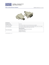
2.3 The Front Panel
The KVM ServSwitch’s front panel features three pushbutton switches and several
LED indicators. To familiarize yourself with these controls and indicators, refer to
Figure 2-1 below and the descriptions that follow.
Figure 2-1. The front panel of a KVM 4 to 1 ServSwitch (SW722).
POWER: Power LED: Lights to indicate that the unit is powered ON.
ON/OFF: Power Button: Pressing this button turns the unit ON and OFF when
the power supply is plugged into the unit and into a working outlet.
CPU STATUS: CPU Status LEDs: Numbered pairs of LEDs indicate the statuses of
the CPUs connected to the corresponding ports on the rear panel:
SELECT or CURRENT PORT (red)
Lights if the corresponding port is the currently selected port.
ON or CPU POWER (green)
Lights if the device on the corresponding port is powered ON.
NOTE
The 2- and 4-port models both share the same chassis, which has 4
each of the SELECT and ON LED slots.

12
“R2” SERVSWITCH
NEXT: Next Port Button: Press this button to manually switch the shared
monitor, keyboard, and mouse from the currently selected computer to
the next one in sequence.
SCAN: Scan-Mode Button: When the ServSwitch is ON and operating normally
(not scanning), press the button once to put the button in the “in”
position. This causes the unit to begin automatic sequential scanning of
connected ports. (If the scan does not begin immediately, quickly press the
button twice more, so that it moves to the “out” position and back to the
“in” position again.) Pressing the button again (returning it to the “out”
position”) ends the scan. For normal operation, the SCAN button should
be “out.” If the system doesn’t function normally after you return the
SCAN button to the “out” position, perform a factory reset (see Section
5.1).
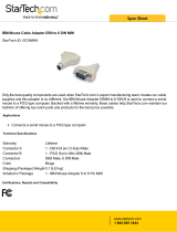
2.4 The Rear Panel
All cable connections are made at the ServSwitch’s rear panel, as illustrated in
Figure 2-2 and described on the next page.
Figure 2-2. The rear panel of a KVM 4 to 1 ServSwitch (SW722).

13
CHAPTER 2: Introduction
Panel Label Connector Description
CPU X DB25 F Connect the sharing computers to these ports
[X = a number with “CPU Adapter Cables.” At the switch end
from 1 to either 2, these cables have a DB25 male connector; at
or 4, depending on the other ends, they have appropriate
which model you connectors to plug into your CPU’s video,
have] keyboard, and mouse ports. These cables take
the signals that would normally pass between
the CPU’s ports and the monitor, keyboard, and
mouse, and carry them between the CPUs’ ports
and the ServSwitch instead.
CPU X For each CPU you plan to connect, you
(continued) must have an Adapter Cable. See Section 2.5.
NOTE
The 2- and 4-port models both share the same chassis, which has 4 CPU
X connector slots. The extra connector slots in the chassis of the 2-port
models are left blank, but are protected by material mounted inside the
chassis.
MONITOR/ DB25 F Connect the shared monitor, keyboard, and
KEYBOARD/ mouse to this port using an “MKM Adapter
MOUSE Cable.” At the switch end, this cable has a DB25
male connector; at the other ends, it has
appropriate connectors to plug into your monitor,
keyboard, and mouse cables. Only one MKM
Adapter Cable is needed. See Section 2.5.
RS-232 RJ-11 F If you connect a more distant computer
or terminal to this RS-232 serial port, you’ll be
able to send switching commands to the
ServSwitch from a secondary location.

14
“R2” SERVSWITCH
Panel Label Connector Description
POWER 5-pin Connect the ServSwitch’s power supply cord
DIN F here. This is not a keyboard input. Power
transformers are available for 110 VAC or 230
VAC. Both have center-tapped output of 17 VAC
at 700 mA.
2.5 Cable Requirements
Many switches of this type have what seems like ten million connectors on their
rear panels: one for each CPU’s video cable, one for each keyboard cable, and a
third for each mouse cable. The potential for tangling or mismatching cables is
high.
By contrast, you can connect the ServSwitch to your CPUs with one “CPU Adapter
Cable” for each CPU. This single cable reaches the CPU’s video output, keyboard,
and mouse ports.
Lastly, you can connect the ServSwitch to the shared monitor, keyboard, and
mouse with a single “MKM Adapter Cable.”
The exact variety or varieties of these cables that you’ll need will depend on the
equipment you are connecting for your application. Refer to Appendix B for the
available types of these cables and the corresponding product codes. Also refer to
Chapter 1 for information about maximum cabling distances.
NOTES
SVGA (over longer distances) and XGA video place special demands on
cabling that the regular MKM Adapter Cables and CPU Adapter Cables
typically cannot meet. For these applications, you should use coaxial
cables that can carry video signals not only farther but also at higher
resolutions. See Appendix B. To carry true monochrome video, or to
share a 9515, 9517, or 9518 monitor, you will need special cabling. Call
Black Box for technical support; we can give you a quote on these types
of cable.
For systems in which some CPUs output EGA video and others output VGA, SVGA,
or XGA, you would need regular VGA-type or coaxial SVGA/XGA-type CPU
Adapter Cables for all CPUs, as well as an EGA-to-VGA adapter for each EGA
computer. Call for a quote on EGA-to-VGA adapters.

15
3. Installation
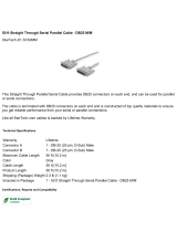
3.1 Quick Setup Guide
Figure 3-1 shows a basic example of connecting a CPU, a keyboard, a monitor, and
a mouse to the ServSwitch. Connectors will vary depending on the types of
equipment you are installing.
Figure 3-1. Basic system setup of a 4-port (SW722-R2) unit.
CHAPTER 3: Installation
SERVSWITCH
Power Supply
17 VAC CT
Monitor/
Keyboard/
Mouse
Adapter
Cable
Mouse
Mouse
Keyboard
Keyboard
CPU Adapter Cable
Monitor
Video Card

16
“R2” SERVSWITCH
3.2 Installation Procedure
This section provides complete basic instructions for the hardware setup of a single
ServSwitch. For an illustrated example of the elements of a basic setup, see Figure
3-1 on the previous page.
3.2.1 R
ACKMOUNTING
(O
PTIONAL
)
If you want to mount the ServSwitch in a 19" rack, you will need a ServSwitch
Rackmounting Kit (our product code SW727 for the 2- and 4-port models). The
ServSwitch is pre-drilled to accept the kit’s rackmounting screws. If you want to
mount the Switch in a 23" or 24" rack, call Black Box for a special quote on a 23" or
24" kit.
3.2.2 C
ONNECTING THE
M
ONITOR
, K
EYBOARD
,
AND
M
OUSE
A Monitor/Keyboard/Mouse (MKM) Adapter Cable connects your monitor,
keyboard, and mouse to the ServSwitch. Because various styles of electrical
connectors are used by different classes of equipment, we supply this cable in
various styles to match (see Appendix B). This cable also comes in the different
lengths supported by different applications (see Section 4.1.3 and Appendix B).
CAUTION
Make sure that the monitor, keyboard, and mouse you plan to use can
meet the demands of your application. See Section 4.1. Also, note that
the ServSwitch does not support dongles at the time of this writing.
1. After you verify that the ServSwitch is turned OFF, plug the DB25 male
connector of the user cable into the port labeled
MONITOR/KEYBOARD/MOUSE on the ServSwitch’s rear panel.
2. Plug the cables from your shared monitor, keyboard, and mouse into the
corresponding connectors on the other ends of the user cable.
3.2.3 C
ONNECTING
CPU
S
CPU Adapter Cables run from the ServSwitch to the keyboard port, mouse port,
and video port of each CPU you want to directly attach to it. Different types of this
cable fit the connectors on different computers (see Appendix B). This cable also
comes in the different lengths supported by different applications (see Section
4.1.3).

17
CHAPTER 3: Installation
CAUTION!
Avoid routing cable near fluorescent lights, air-conditioning
compressors, or machines that may create electrical noise. Total length
of original Serv cable from the keyboard, monitor, and mouse to any
given CPU should not exceed 25 ft. (7.6 m). For typical equipment and
video resolutions, length of coaxial cable should not exceed the 20 ft.
(6.1 m) from a ServSwitch to any attached device (keyboard, monitor,
mouse, or CPU). However, we do provide coaxial cable in lengths up to
100 ft. (30.5 m), because some CPUs can drive and receive keyboard
and mouse signals at greater distances than others; consult with the
manufacturers of your CPUs about this.
1. Plug the DB25 male connector of the first CPU’s CPU Adapter Cable into the
lowest-numbered CPU port on the ServSwitch’s rear panel that isn’t going to
be occupied by a submaster Serv type switch. Use consecutively higher-
numbered ports for the rest of the CPUs.
2. Plug the CPU Adapter Cable’s video-, keyboard-, and mouse-port connectors
into the corresponding ports on the CPU. The CPU should be OFF when you
do this; the Switch will automatically adjust to the CPU’s keyboard mode
when you power up the CPU.
CAUTION!
Do not attach docking stations or ThinkPad
®
or other portable
computers, no matter what type or make, to the ServSwitch. At the time
of this writing, the ServSwitch does not support docking stations; your
ServSwitch system might not function properly if any are attached.
3.2.4 P
OWERING
U
P THE
S
YSTEM
1. Making sure that the connected CPUs are OFF (powered down), take the
output cord of the ServSwitch’s power supply and plug its 5-pin DIN male
connector into the power jack on the rear panel of the switch. Plug the power
supply (115 VAC) or its input cord (230 VAC) into a working outlet.
2. Push the ON/OFF button on the front of the ServSwitch to power up the
switch.
3. Power up the connected CPUs one by one, giving each one time to boot
completely before turning ON the next one. When the CPUs are powered up
after the ServSwitch, the switch emulates all keyboard and mouse functions
for automatic boot-up, although you might have to issue the Mode command
Mn (see Section 4.3.7) to get proper keyboard communication.

18
“R2” SERVSWITCH
3.2.5 S
WITCHING FROM THE
K
EYBOARD
Your ServSwitch is now ready for operation using its default settings. To take full
advantage of the switch’s features, refer to Chapter 4, which gives detailed
information about each of the ServSwitch commands, describing each command’s
function and keystroke sequence. For your convenience, this information is
summarized in Section 4.2. To begin switching immediately, however, just press
and release your keyboard’s left Control Key ([CTRL]), then—within the next two
seconds—type in your desired port number with the regular number keys (not the
numeric keypad).
Page is loading ...
Page is loading ...
Page is loading ...
Page is loading ...
Page is loading ...
Page is loading ...
Page is loading ...
Page is loading ...
Page is loading ...
Page is loading ...
Page is loading ...
Page is loading ...
Page is loading ...
Page is loading ...
Page is loading ...
Page is loading ...
Page is loading ...
Page is loading ...
Page is loading ...
Page is loading ...
Page is loading ...
Page is loading ...
Page is loading ...
Page is loading ...
Page is loading ...
Page is loading ...
Page is loading ...
Page is loading ...
/