Audio 2, 4, or 6-channel conguration
Port Headset 2-channel 4-channel 6-channel
Light Blue Line In Line In Line In
Lime Line Out Front Speaker Out Front Speaker Out
Pink Mic In Mic In Mic In
Orange – – Center/Subwoofer
Black – Rear Speaker Out Rear Speaker Out
Gray – – –
Refer to the audio conguration table below for the function of the audio ports in a 2, 4, or
6-channel conguration.
• DO NOT connect a keyboard / mouse to any USB 3.0 port when installing Windows
®
operating system.
• Due to USB 3.0 controller limitation, USB 3.0 devices can only be used under Windows
®
OS environment and after the USB 3.0 driver installation.
• USB 3.0 devices can only be used as data storage only.
• We strongly recommend that you connect USB 3.0 devices to USB 3.0 ports for faster
and better performance for your USB 3.0 devices.
8. Side Speaker Out port (gray)Side Speaker Out port (gray). This port connects the side speaker in an 8-channel
audio conguration.
9. Rear Speaker Out port (black). This port connects the rear speakers in a 4-channel,
6-channel, or 8-channel audio conguration.
10. Center / Subwoofer port (orange)Center / Subwoofer port (orange). This port connects the center/subwoofer speakers.
11. Microphone port (pink).Microphone port (pink). This port connects to a microphone.
12. Line Out port (lime).Line Out port (lime). This port connects to a headphone or speaker. In a 4, 6, or
8-channel conguration, the function of this port becomes Front Speaker Out.
13. Line In port (light blue).Line In port (light blue). This port connects to a tape, CD, DVD player, or other audio
sources.
7. USB 3.0 ports.USB 3.0 ports. These Universal Serial Bus 3.0 (USB 3.0) ports connect to USB 3.0
devices such as a mouse, printer, scanner, camera, PDA, and others.
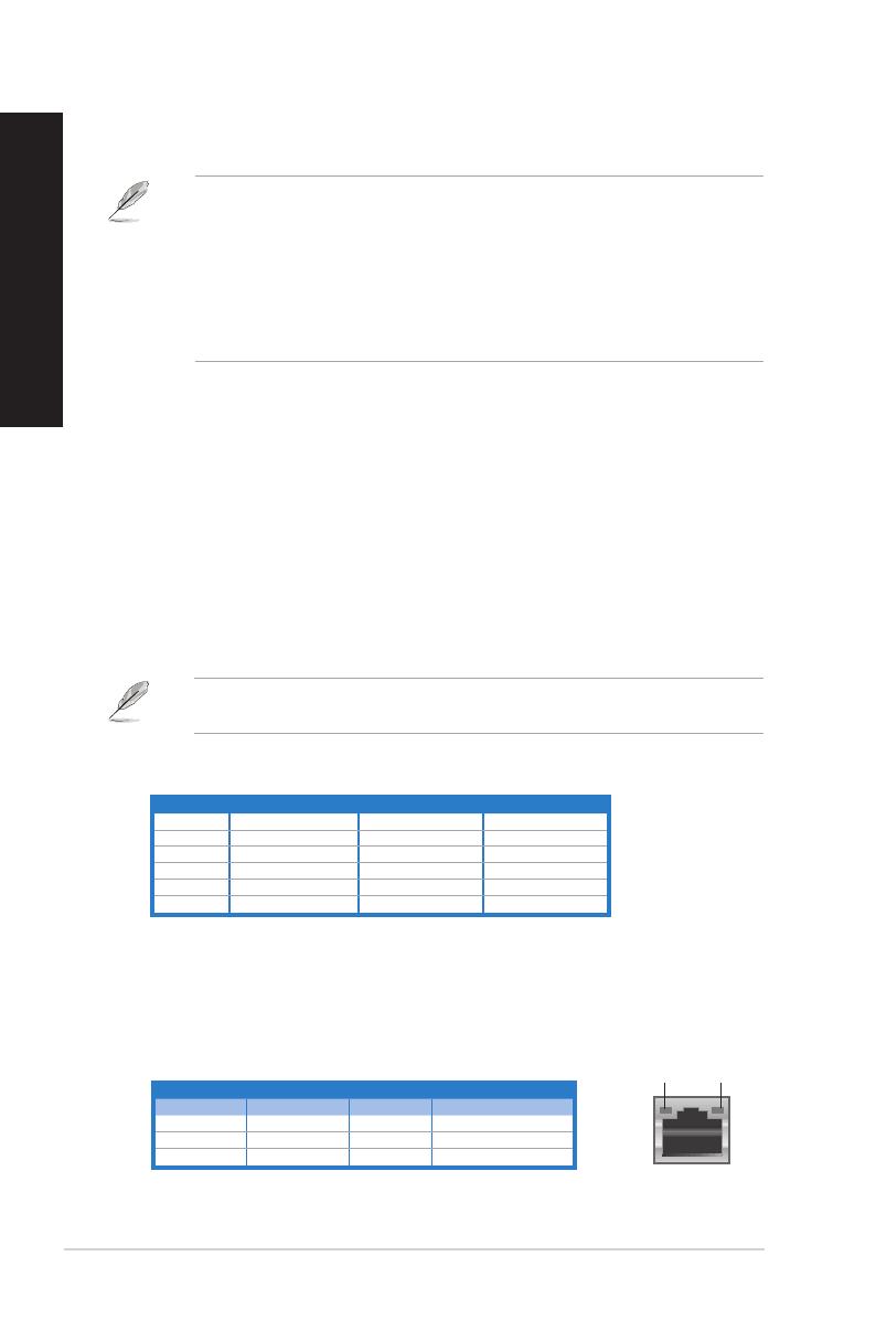
Activity/Link LED Speed LED
Status Description Status Description
OFF No link OFF 10Mbps connection
ORANGE Linked ORANGE 100Mbps connection
BLINKING Data activity GREEN 1Gbps connection
LAN port
SPEED
LED
ACT/LINK
LED
14. Expansion slot brackets.Expansion slot brackets. Remove the expansion slot bracket when installing an
expansion card.
15. LAN (R�-45) port.LAN (R�-45) port. This port allows Gigabit connection to a Local Area Network (LAN)
through a network hub.
LAN port LED indications
16 Chapter 1: Getting started
ENGLISH
ENGLISH


