Page is loading ...

NOVUS AUTOMATION 1/8
RHT-P10 Transmitter
INSTRUCTIONS MANUAL - V2.0x A

NOVUS AUTOMATION 2/8
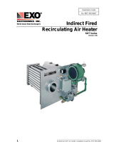
1 PRESENTATION
RHT-P10 transmitter features a highly accurate and stable sensor for measuring relative humidity and temperature. The measured values are
converted into 4 to 20 mA output signals linearly related to their readings. Optionally, the outputs can be offered in 0 to 10 Vdc voltage.
The microprocessor-based circuit enables full configuration of output range when used with the TxConfig PC interface and the Windows software.
Humidity measurement and transmission can be configured between Relative Humidity and Dew Point.
2 INSTALLATION
2.1 MECHANICAL INSTALLATION
The electronics module of the RHT-P10 must be fixed to the wall. The remote sensor module, on the other hand, must be inserted into a threaded
flange.
By removing the cover of the transmitter electronic module, the user has access to the two fixing holes, as shown in the figure below:
Figure 1 – Electronic module dimensions Figure 2 – Fixing holes
The figures below show the dimensions of the remote sensor module and the mounting flange:
Figure 3 – Remote sensor module Figure 4 – Mounting flange
Note: The mounting flange is not included with the transmitter. It must be purchased separately.
2.2 ELECTRICAL INSTALLATION
The transmitter can be ordered as 4-20 mA current output or 0 to 10 Vdc voltage output. The output signal type is defined at the time of purchase
of the transmitter and cannot be changed later.
Variables can be monitored together or separately. Combinations of mobile jumpers J4 and J5 within the transmitter housing define how variables
will be used. These jumpers also define the transmitter terminals where the output signals will be available.
Jumper J5 Jumper J4 OUT1 OUT2
Position
A
Position
A
Temperature
Humidity
Position A
Position B
Temperature
Off
Position B
Position A
Humidity
Off
Position B Position B Humidity Temperature
Table 1 – OUT1 and OUT2 configuration

NOVUS AUTOMATION 3/8
Figure 5 – Location of J4 and J5 jumpers inside the transmitter
The figures below show the required electrical connections.
The loop OUT1 must always be powered in the 4-20 mA model!
Figure 6 – 4-20 mA connections Figure 7 – 0-10 Vdc connections
Figure 8 – 4-20 mA connections (one power supply) Figure 9 – 4-20 mA connections (one power supply and load
with 2 input channels)
In the figures above, LOAD represents the measuring instrument of the output signal (indicator, controller, register, etc.).
The connection wires go inside the transmitter trough to the cable gland mounted in the transmitter housing.
INSTALLATION RECOMMENDATIONS
• Conductors of small electric signals must be separated from activation conductors or higher current or power in the system plan. If possible, in
grounded conduits.
• The instrument supply must come from a network proper for instrumentation.
• In control and monitoring applications, it is essential to consider what may happen when any part of the system fails.
• It is recommended to use RC FILTERS (47 Ω and 100 nF, series) in parallel with coils of contactors and solenoids, etc.
CARE WITH THE SENSORS
The calibration of the humidity sensor may change in case it is exposed to contaminating vapors or to high humidity and temperature conditions for
extended periods. To speed up the calibration restoration, proceed as described below:
• Remove the sensor from the capsule.
• Wash it with water in case there are solid particles on it.
• Place it within an 80 °C (176 °F) (±10 °C) oven for 24 hours.
• Place it for 48 hours in a place with a temperature between 20 °C (68 °F) and 30 °C (86 °F) and humidity over 75 % RH.
• Place the sensor back in the capsule.

NOVUS AUTOMATION 4/8
3 CONFIGURATION
If the default configuration or the ordered configuration satisfies the application, then no further configuration is necessary, and the transmitter is
ready to be used. If a new setting is desired, this can be accomplished by the TxConfig and sent to the transmitter through the TxConfig USB
interface.
The TxConfig interface and software compose the Transmitter Configuration Kit, with can be purchased separately from the manufacturer or
one of its distributors. The latest release of this software can be downloaded from our website. To install it, run the Tx_setup.exe and follow the
instructions.
The TxConfig interface connects the transmitter to the PC, as shown in the figure below:
Figure 10 – TxConfig Interface USB connections
Once the connection is accomplished, the user must run the TxConfig software and, if necessary, use the Help topic to arrange the transmitter
configuration.
The figure below shows the TxConfig software main screen:
Figure 11 – TxConfig software main window
The fields in the screen mean:
1. Measuring Range: Define the transmitter humidity and temperature measurement ranges, indicating a Lower Limit value and an Upper Limit
value.
The defined range cannot exceed the Sensor Measuring shown in this same field and cannot establish a range with a span less than the
Minimum Range indicated below in this same field.
When the Lower Limit is set to a value higher than the Upper Limit, the output current has a decreasing behavior (20 ~ 4 mA or 10 ~ 0 V).
2. Sensor Failure: Establish the transmitter output behavior in the presence of a sensor fail. When Minimum is selected, the output assumes its
minimum value (4 mA / 0 V) (down-scale). When Maximum is selected, it assumes its maximum value (20 mA / 10 V) (up-scale).
3. Zero Correction: Correct, in the output value, small measurement errors presented by the transmitter.
4. Device Information: This field contains data that identifies the transmitter and is important in any queries to the manufacturer.
5. Read Device: When selected, allows you to read the configuration present on the connected transmitter.
6. Apply: When pressed, allows you to send the configuration to the connected transmitter.
Note: The factory default configuration is (unless otherwise specified or ordered):
• Measuring ranges: 0 to 100 °C (32 to 212 °F) and 0 to 100 % RH.
• 0 °C (32 °F) of correction zero.

NOVUS AUTOMATION 5/8
• Output at maximum value for sensor failures.
It is important to notice that the transmitter accuracy is always based on the total span of the used sensor, even if a narrower range is configured.
Example:
The humidity sensor has a maximum range of 0 to 100 % RH and an accuracy of 3 % at 25 °C (77 °F), as shown in Figure 13. We can have
an error of up to 3 % RH in any adopted range.
This error is even in a wide range as the maximum (0 to 100 % RH) or in a narrower range, such as 20 to 80 % RH.
Serial port configuration error may occur when other software uses the same serial port. Finalize all software that uses the serial port
specified for TxConfig before using it.
3.1 RETRANSMITTING THE DEW POINT
To use the RHT-P10 and transmit the dew point instead of relative humidity, you must follow the steps below:
• Connect the device to the TxConfig interface and run the software.
• The software will recognize the RHT-P10 model, read its configuration, and make it available to the user.
• In the "Options" menu, enter "Humidity Reading Type" (only available when an RHT-P10 model is detected) and select the "Dew Point" option.
At this point, the values of the scales will be converted to the dew point unit, i.e., degrees (Celsius or Fahrenheit, as selected).
• Proceed with the rest of the configuration and send the device via the "Apply" button.
Figure 12 – Dew point
If the "Humidity Reading Type" option does not appear even after the RHT-P10 transmitter is correctly detected, the TxConfig software version is
old and does not support this feature. In this case, download and update the latest version.

NOVUS AUTOMATION 6/8
4 SPECIFICATIONS
Humidity measurement
Total accuracy: See Figure 13.
Measuring range: Configurable between 0 and 100 % RH or -100 and 103 °C (-148 and 217.4 °F) for
dew point.
Response time (1/e (63 %)): 8 seconds @ 25 °C (is slow moving air 1 m/s).
Temperature measurement
Total accuracy: See Figure 13.
Total accuracy: Configurable between -40 and 120 °C (-40 and 248 °F).
Response time (1/e (63 %)): up to 30 s (is slow moving air 1 m/s).
Power supply 4-20 mA model: 12 Vdc to 30 Vdc
0-10 V model: 18 a 30 Vdc / 15 mA max.
Sensor reading range < 1.5 seconds
Outputs 4-20 mA or 20-4 mA current, 2-wire loop power supply.
0-10 Vdc tension / 2 mA max.
Output Load (RL) 4-20 mA model: RL (Ohms max.) = (Vdc - 12) / 0.02 let: Vdc = Power supply in Volts.
0-10 Vdc model: 2 mA max.
OUT1 output resolution 0.006 mA (4-20 mA) or 0.003 V (0-10 V).
OUT2 output resolution 0.022 mA (4-20 mA) or 0.015 V (0-10 V).
Isolation between loops The 4-20 mA outputs are isolated from each other. The 0-10 V outputs are not isolated from each other.
Provides protection against
power supply polarity
inversion
Yes
Protection Electronic circuit housing: IP65
Sensor capsule: IP40
Cable entrance Compress fitting PG7.
Operating limits Sensor (RHT-P10): See Figure 13.
Maximum differential pressure: 10 Bar (145 PSI).
Electronic circuit
Electronic circuit (RHT-P10):
Operating temperature: -10 to 65 °C (14 to 149 °F), 0 to 95 % RH
Storage temperature: -20 to 80 °C (-4 to 176 °F)
Certifications
CE Mark
This is a Class A product. In a domestic environment, this product may cause radio interference in which
case the user may be required to take adequate measures.
Table 2 – Technical specifications
IMPORTANT
The transmitter sensor may be damaged or lose calibration if it is exposed to aggressive atmospheres with high concentrations as Chloride Acid,
Nitride Acid, Sulfuric Acid and Ammonia. Acetone, Ethanol and Propylene Glycol may cause reversible measurement errors.

NOVUS AUTOMATION 7/8
4.1 MEASUREMENT ACCURACY AND OPERATIONAL LIMITS OF THE SENSORS
Figure 13 – Humidity and temperature accuracies

/