5
ADDITIONAL DISPLAY ITEMS
BATTERY INDICATORSOPERATING MODE INDICATORS
TEST
MUTE
1
2
3
4
5
10
9
7
6
8
11
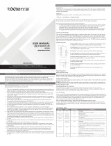
LCD Display
The LCD Display indicates a variety
of UPS modes and operating
conditions. To view the various
screens, press the
button
while the UPS is operating in line or
battery power mode.
The LCD DISPLAY is shown here
fully illuminated to identify all
available icons and labels. This is
for explanation only—there are no
operating modes where the screen
is fully illuminated like this except
for a few seconds as the UPS is first
plugged in.
5. BATTERY CHARGE METER continuously reports battery charge level.
6. LOAD LEVEL METER continuously reports load-level on UPS supported outlets.
7. OVERLOAD ICON comes on to report that UPS supported outlets are overloaded.
8. 3-DIGIT DISPLAY lights along with associated labeling and icons to report a variety
of UPS and site power related conditions.
9. 3-DIGIT DISPLAY SUFFIX display labels will selectively illuminate to describe the
unit of measurement the 3-digit display is currently reporting (V=volts, %=percent,
A=amps, kW=kilowatts, Hz=frequency, Min=minutes).
10. 3-DIGIT DISPLAY PREFIXES
• INPUT lights to indicate the 3-digit display is reporting an input condition (input
voltage, input frequency)
• OUTPUT lights to indicate the 3-digit display is reporting an output condition
(output voltage, output Hz, etc)
• BATTERY lights to indicate the 3-digit display is reporting a battery related
condition (battery voltage)
• ESTIMATED RUNTIME lights to indicate that the 3-digit display is currently
reporting estimated runtime in minutes
11. FAULT ICON lights to indicate a variety of possible UPS fault conditions (see Error
Messages section for information on other reported faults)
1. ON-LINE MODE ICON indicates that AC
power is present and the UPS is running
from an input line power source.
2. AVR BUCK & AVR BOOST ICONS will
selectively illuminate during line power
mode to indicate Automatic Voltage
Regulation (AVR) is engaged. “AVR”
& “BUCK” indicates an overvoltage
condition and output is reduced back
to usable levels. “AVR” & “BOOST”
indicates brownout/undervoltage
conditions and output is boosted back
to usable levels.
3. ON BATT ICON indicates that the UPS
is running in battery mode, due to
power failure or severe input voltage
fluctuation.
4. REPLACE BATTERY ICON will illuminate
to inform users that the UPS battery is
weak and requires replacement.
Basic Operation continued
15-02-071-9332B0.indb 5 2/18/2015 10:17:52 AM