Page is loading ...


Revision history Table of revisions
Date Changed Rev
April 2017 First edition 0101
Service Manual
Series 45 Frame K2 Open Circuit Axial Piston Pumps
2 |
©
Danfoss | April 2017 AX00000301en-US0101

Introduction
Using this manual.............................................................................................................................................................................5
Safety precautions............................................................................................................................................................................5
Unintended machine movement..........................................................................................................................................5
Flammable cleaning solvents.................................................................................................................................................5
Fluid under pressure..................................................................................................................................................................5
Personal safety.............................................................................................................................................................................5
Symbols used in Danfoss literature............................................................................................................................................6
General description......................................................................................................................................................................... 6
Technical specifications
General specifications.....................................................................................................................................................................8
Type of mounting....................................................................................................................................................................... 8
Auxiliary mounting pad options............................................................................................................................................8
Control options............................................................................................................................................................................8
Port options...................................................................................................................................................................................8
Direction of rotation...................................................................................................................................................................8
Installation position....................................................................................................................................................................8
Technical specifications............................................................................................................................................................8
Hydraulic parameters......................................................................................................................................................................9
Inlet pressure................................................................................................................................................................................9
Pressure compensator valve setting....................................................................................................................................9
Case pressure................................................................................................................................................................................9
Hydraulic fluid .............................................................................................................................................................................9
Temperature range.....................................................................................................................................................................9
Fluid viscosity............................................................................................................................................................................... 9
Filtration ........................................................................................................................................................................................ 9
Features
Displacement limiter.....................................................................................................................................................................10
Auxiliary mounting pads.............................................................................................................................................................10
Input shafts.......................................................................................................................................................................................11
Control options...............................................................................................................................................................................11
Operation.....................................................................................................................................................................................11
General....................................................................................................................................................................................11
PC control...............................................................................................................................................................................12
LS control............................................................................................................................................................................... 12
Electronic Controls...................................................................................................................................................................13
Electric Dump Valve PC/LS Controls.............................................................................................................................15
Pressure measurement
Required tools.................................................................................................................................................................................16
Port locations and gauge installation.....................................................................................................................................16
Initial start-up procedures
General...............................................................................................................................................................................................18
Start-up procedure........................................................................................................................................................................18
Fluid and filter maintenance
Recommendations........................................................................................................................................................................ 19
Troubleshooting
Excessive noise and/or vibration..............................................................................................................................................20
Actuator response is sluggish....................................................................................................................................................20
System operating hot...................................................................................................................................................................20
Low pump output flow................................................................................................................................................................21
Pressure or flow instability..........................................................................................................................................................21
System pressure not reaching PC setting............................................................................................................................. 22
High inlet vacuum..........................................................................................................................................................................22
Adjustments
PC control..........................................................................................................................................................................................23
Service Manual
Series 45 Frame K2 Open Circuit Axial Piston Pumps
Contents
©
Danfoss | April 2017 AX00000301en-US0101 | 3

LS control..........................................................................................................................................................................................24
Minor repair
Shaft seal replacement.................................................................................................................................................................26
Disassembly................................................................................................................................................................................26
Inspection....................................................................................................................................................................................26
Reassembly.................................................................................................................................................................................26
Displacement limiter.....................................................................................................................................................................27
Disassembly................................................................................................................................................................................27
Inspection....................................................................................................................................................................................27
Reassembly.................................................................................................................................................................................27
Servo piston..................................................................................................................................................................................... 27
Disassembly................................................................................................................................................................................27
Inspection....................................................................................................................................................................................28
Reassembly.................................................................................................................................................................................28
Auxiliary pads..................................................................................................................................................................................28
Disassembly................................................................................................................................................................................28
Inspection....................................................................................................................................................................................29
Assembly......................................................................................................................................................................................29
LS and PC Controls.........................................................................................................................................................................29
Electric Controls..............................................................................................................................................................................33
Fan Drive Control...........................................................................................................................................................................34
Servo Control Orifice.....................................................................................................................................................................36
Servo Control Orifice Disassembly..................................................................................................................................... 36
Servo Control Orifice Reassembly.......................................................................................................................................37
Plug and fitting sizes and torques........................................................................................................................................... 37
Service Manual
Series 45 Frame K2 Open Circuit Axial Piston Pumps
Contents
4 |
©
Danfoss | April 2017 AX00000301en-US0101

Using this manual
This manual includes information for the normal operation, maintenance, and service of the Series 45 K2
frame open circuit pumps. The manual includes a description of the units and their individual
components, troubleshooting information, adjustment instructions and minor repair procedures. Unit
warranty obligations should not be affected if maintenance, adjustment and minor repairs are performed
according to the procedures described in this manual.
Many service and adjustment activities can be performed without removing the unit from the vehicle or
machine. However, adequate access to the unit must be available, and the unit must be thoroughly
cleaned before beginning maintenance, adjustment, or repair activities. Since dirt and contamination are
the greatest enemies of any type of hydraulic equipment, follow cleanliness requirements strictly. This is
especially important when changing the system filter and when removing hoses or plumbing.
A worldwide network of Danfoss Authorized Service Centers (ASCs) is available should major repairs be
needed. Contact any Danfoss ASC for details. A list of all ASCs can be found in bulletin BLN-2-40527, or in
brochure SAW (Ident. No. 698266), or you can locate your nearest ASC using the distributor locator at
http://www.powersolutions.danfoss.com
Safety precautions
Always consider safety precautions before beginning a service procedure. Protect yourself and others
from injury. Take the following general precautions whenever servicing a hydraulic system.
Unintended machine movement
W
Warning
Unintended movement of the machine or mechanism may cause injury to the technician or bystanders.
To protect against unintended movement, secure the machine or disable / disconnect the mechanism
while servicing.
Flammable cleaning solvents
W
Warning
Some cleaning solvents are flammable. To avoid possible fire, do not use cleaning solvents in an area
where a source of ignition may be present.
Fluid under pressure
W
Warning
Escaping hydraulic fluid under pressure can have sufficient force to penetrate your skin causing serious
injury and/or infection. This fluid may also be hot enough to cause burns. Use caution when dealing with
hydraulic fluid under pressure. Relieve pressure in the system before removing hoses, fittings, gauges, or
components. Never use your hand or any other body part to check for leaks in a pressurized line. Seek
medical attention immediately if you are cut by hydraulic fluid.
Personal safety
W
Warning
Protect yourself from injury. Use proper safety equipment, including safety glasses, at all times.
Service Manual
Series 45 Frame K2 Open Circuit Axial Piston Pumps
Introduction
©
Danfoss | April 2017 AX00000301en-US0101 | 5

Symbols used in Danfoss literature
WARNING may result in injury Tip, helpful suggestion
CAUTION may result in damage to product or
property
Lubricate with hydraulic fluid
Reusable part Apply grease / petroleum jelly
Non-reusable part, use a new part Apply locking compound
Non-removable item Inspect for wear or damage
Option - either part may exist Clean area or part
Superseded - parts are not interchangeable Be careful not to scratch or damage
Measurement required Note correct orientation
Flatness specification Mark orientation for reinstallation
Parallelism specification Torque specification
External hex head Press in - press fit
Internal hex head Pull out with tool – press fit
Torx head Cover splines with installation sleeve
O-ring boss port Pressure measurement/gauge location or
specification
The symbols above appear in the illustrations and text of this manual. They are intended to communicate
helpful information at the point where it is most useful to the reader. In most instances, the appearance
of the symbol itself denotes its meaning. The legend above defines each symbol and explains its purpose.
General description
Danfoss Series 45 K2 frame open circuit piston pumps convert input torque into hydraulic power.
Rotational force is transmitted through the input shaft to the cylinder block. The input shaft is supported
by tapered roller bearings at the front and rear of the pump and is splined into the cylinder block . A lip-
seal at the front end of the pump prevents leakage where the shaft exits the pump housing. The spinning
cylinder block contains nine reciprocating pistons. Each piston has a brass slipper connected at one end
by a ball joint. The slippers are held to the swashplate by the spring retainer and block spring. The block
spring also holds the cylinder block to the valve plate. The reciprocating movement of the pistons occurs
as the slippers slide against the inclined swashplate during rotation. Via the valve plate, one half of the
cylinder block is connected to pump inlet and the other half to pump outlet. As each piston cycles in and
out of its bore, fluid is drawn from the inlet and displaced to the outlet thereby imparting power into the
system circuit. A small amount of fluid is allowed to leak from the cylinder block / valve plate and slipper /
swashplate interfaces for lubrication and cooling. Case drain ports are provided to return this fluid to the
reservoir.
The volume of fluid displaced into the system circuit is controlled by the angle of the swashplate. The
swashplate is forced into an inclined position (into stroke) by the bias spring. The servo piston opposes
the action of the bias spring forcing the swashplate out of stroke when hydraulic pressure in the control
circuit rises above the spring force.
The pump control, by varying the pressure at the servo piston, controls the displacement of fluid in the
system circuit. Controls designed for Pressure Compensation (PC) or Load Sensing (LS) are available. For a
detailed description of control operation, refer to Control options, operation.
Service Manual
Series 45 Frame K2 Open Circuit Axial Piston Pumps
Introduction
6 |
©
Danfoss | April 2017 AX00000301en-US0101

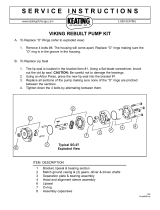
Pump and control sectional view
P109038
Bias spring
Piston
Input shaft
Block spring
Servo piston
Swashplate
Valve plate
Endcap
(axial ported)
Slipper
Slipper retainer
Cylinder block
Shaft seal
Tapered roller bearing
LS spool
LS adjustment
PC adjustment
PC spool
LS control
(attached to endcap)
Service Manual
Series 45 Frame K2 Open Circuit Axial Piston Pumps
Introduction
©
Danfoss | April 2017 AX00000301en-US0101 | 7

General specifications
Type of mounting
SAE-B mounting flange.
Auxiliary mounting pad options
SAE-A, SAE-B, or SAE-B-B
Control options
PC: Pressure Compensator
LS: Load Sensing (with PC)
Port options
Inlet and system ports:
•
SAE flanged ports, code 61 or O-ring boss ports.
•
Axial (end) ports or radial (side) ports.
All other ports:
•
SAE straight thread O-ring boss.
Direction of rotation
Clockwise or counterclockwise.
Installation position
Installation position is discretionary. To satisfy inlet pressure conditions, it is recommended that the
pump always be located below the lowest level of hydraulic fluid in the reservoir. The housing must
always be filled with hydraulic fluid.
Technical specifications
Ratings
Description Unit K2 Frame
25C 30C 38C 45C
Maximum Displacement cm
3
[in
3
] 25 [1.53] 30 [1.83] 38 [2.32] 45 [2.75]
Working Input Speed Minimum min
-1
[rpm] 500 500 500 500
Continuous 3450 3200 2900 2900
Maximum 3750 3450 3050 3050
Working Pressure Continuous bar [psi] 260 [3771] 260 [3771]
Maximum 350 [5075] 350 [5076]
Flow at rated speed (theoretical) l/min [US gal/
min]
86.3 [22.8] 96 [25.4] 110.2 [29.1] 130.5 [34.5]
Input torque at max. displacement
(theoretical) at 49° C [120°F]
N•m/bar [lbf•in/
1000 psi]
0.398 [243] 0.477 [291] 0.605 [369] 0.716 [438]
Mass moment of inertia of internal rotating
components
kg•m
2
[slug•ft
2
] 0.00184 [0.00135] 0.00203 [0.00150]
Weight Axial ports kg [lb] 16 [35]
Radial ports 17 [37]
Service Manual
Series 45 Frame K2 Open Circuit Axial Piston Pumps
Technical specifications
8 |
©
Danfoss | April 2017 AX00000301en-US0101

Hydraulic parameters
Inlet pressure
Minimum pressure, continuous = 0.8 bar absolute [23.2 in Hg]
Minimum pressure, cold start = 0.5 bar absolute [14.8 in Hg] (at reduced maximum pump speed)
Pressure compensator valve setting
Minimum: 100 bar [1450 psi]
Maximum: 260 bar [3770 psi]
Case pressure
Maximum continuous: 0.5 bar [7 psi] Above inlet
Intermittent: 2 bar [29 psi] Cold start
Hydraulic fluid
Refer to Danfoss publication Fluids and Filtration BLN-9887 or 520L0463. For information on biodegradable
fluids refer to Biodegradable Hydraulic Fluids 520L0465. See Fluid and filter maintenance for
recommended fluid and filter change intervals.
Temperature range
Intermittent (cold start): - 40° C [- 40° F]
Continuous: 104°C [219°F]
Maximum
*
: 115°C [239°F]
Hydraulic fluid viscosity must be maintained within the prescribed limits.
Fluid viscosity
Viscosity limits
Rating mm2/s (cSt) [SUS]
ν continuous minimum 9 [58]
maximum 110 [500]
ν intermittent minimum 6.4 [47]
maximum (cold start) 1000 [4700]
Filtration
Required cleanliness level: ISO 4406 Class 18/13 or better. Refer to Danfoss publications Fluids and
Filtration BLN-9887 or 520L0463 and Design Guidelines for Selecting and Maintaining the Required Hydraulic
Fluid Cleanliness 520L0465. See Fluid and filter maintenance for recommended fluid and filter change
intervals.
*
As measured at the hottest point in the system, e.g. drain line.
Service Manual
Series 45 Frame K2 Open Circuit Axial Piston Pumps
Technical specifications
©
Danfoss | April 2017 AX00000301en-US0101 | 9

Displacement limiter
Frame K2 Series 45 pumps are available with an optional maximum displacement limiter. If installed, this
longer servo piston will limit the maximum displacement to 92%. This displacement limiter is not
adjustable.
Fixed displacement limiter
L
P109043
Standard displacement options
Kit size [cm] Angle of swash plate [°] Servo Piston
identification
Displacement [cc/rev] Servo piston length
Dim L [mm]
Swash plate Stroke
[%]
45 18.00 1 45 49.43 100
38 18.00 1 38 49.43 100
38 14.53 5 30 52.8 79
38 12.18 7 25 55.08 66
Special displacement
Kit size [cm] Angle of swash plate [°] Servo Piston
identification
Displacement [cc/rev] Servo piston length
Dim L [mm]
Swash plate Stroke
[%]
45 16.49 2 41 50.9 91
45 16.11 3 40 51.27 89
Frame K2 Series 45 pumps are available with an optional adjustable maximum displacement limiter. The
adjustable stop limits the pump’s maximum displacement.
Adjustable displacement limiter
P109048
Kit size Displacement per turn [cm
3
/turn] Setting range [cm
3
] Angle of swashplate [°] Displacement [cc/rev]
45 4.64 0-45 18.0 45
38 3.81 0-38 18.0 38
38 3.7 0-30 14.5 30
38 3.7 0-25 12.2 25
Auxiliary mounting pads
Auxiliary mounting pads are available for all radial ported Series 45 pumps. These pads are typically used
for mounting auxiliary hydraulic pumps.
Since the auxiliary pad operates under case pressure, an O-ring must be used to seal the auxiliary pump
mounting flange to the pad. The drive coupling is lubricated by oil from the main pump case. For details
refer to Series 45 Axial Piston Open Circuit Pumps Technical Information TIM 520L0519.
Service Manual
Series 45 Frame K2 Open Circuit Axial Piston Pumps
Features
10 |
©
Danfoss | April 2017 AX00000301en-US0101

Auxiliary mounting pads
P109049
Input shafts
Series 45 K2 frame pump is available with a variety of splined, straight keyed, and tapered end shafts. For
information on shafts refer to Series 45 Axial Piston Open Circuit Pumps Technical Information TIM 520L0519.
Control options
The Series 45 K2 Frame has two basic control options, a Load Sensing (LS) control with Pressure Compensator (PC) or a PC only control.
Please refer to Series 45 Open Circuit Axial Piston Pumps Technical Information Manual, 520L0519 for more extensive control options.
Operation
General
The bias spring acts at all times to push the swashplate to maximum angle causing the pump to stroke.
The servo piston acts against the bias spring to reduce the swashplate angle causing the pump to de-
stroke. Swashplate angle determines pump outlet flow. The pump control, depending on conditions in
the system circuit, sets swashplate angle by metering system pressure to the servo piston.
Cross-section pump: Bias spring and servo piston set swashplate position
Bias spring
Swashplate
Servo piston
Service Manual
Series 45 Frame K2 Open Circuit Axial Piston Pumps
Features
©
Danfoss | April 2017 AX00000301en-US0101 | 11

PC control
The PC control is designed to maintain a constant pressure in the hydraulic circuit as flow varies. The PC
control modulates pump flow accordingly to maintain system pressure at the PC setting as defined by
the PC adjustment screw (4) and spring (5).
When system pressure, acting on the non-spring end of the PC spool (6), overcomes the force of the PC
spring, the spool shifts porting system pressure to the servo piston and the swashplate angle decreases.
When system pressure drops below the PC setting, the PC spring shifts the spool in the opposite
direction connecting the servo piston to pump case and the swashplate angle increases. The swashplate
is maintained at whatever angle is required to keep system pressure at the PC setting.
Cross-section PC control: PC spool shifts to port system pressure to servo piston
P104 049
4
5
6
LS control
The LS control is designed to match pump flow with system demand. The flow demand of the system is
sensed by the LS control as a pressure drop across the External Control Valve (ECV). As the ECV opens and
closes, the pressure delta across the valve changes. When opening, the delta decreases. When closing,
the delta increases. The LS control then increases or decreases pump flow to the system until the
pressure delta becomes equal to the LS setting as defined by the LS adjustment screw and spring.
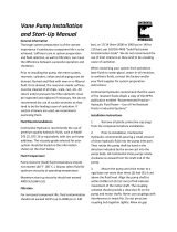
Typical load-sensing control valve
Load
pressure
Load sense
pressure
System
pressure
Tank
Return
pressure
P101 665E
Pressure drop across external control valve defines system demand
Cross-section LS control
Spool
Spring
guide
Spring
LS adjusting
plug
LS spring
PC adjusting
plug
Plug
Plug
Spool
Spring
guide
Spring
(PC heavy)
P104 051
The LS control consists of two spool valves that connect the servo piston either to pump case or system
pressure. The PC spoolcontrols the pressure-compensating function of the control as described in the
previous section. The LS spool controls the load-sensing function. The PC spool has priority over the LS
spool.
Via internal porting, system pressure (upstream of ECV) is applied to the non-spring end of the LS spool
and via hydraulic line connected at port X, LS pressure (downstream of ECV) is applied to the spring end.
This arrangement allows the LS spool to act on the delta between system pressure and LS pressure. The
LS spring sets the threshold of operation (LS setting).
Service Manual
Series 45 Frame K2 Open Circuit Axial Piston Pumps
Features
12 |
©
Danfoss | April 2017 AX00000301en-US0101

Because the swashplate is biased to maximum angle, the pump attempts to deliver full flow to the
hydraulic system. When the flow being delivered exceeds demand, the pressure delta across the ECV is
great enough to overcome spring force and shift the LS spool porting system pressure to the servo
piston. The pump de-strokes reducing flow until the delta across the ECV becomes equal to the LS
setting. When flow being delivered is less than demand, the delta across the ECV drops below the LS
setting and the LS spring shifts the spool connecting the servo piston to pump case. The pump strokes
increasing flow until the delta across the ECV becomes equal to the LS setting.
When the external control valve is placed in neutral, it connects the LS signal line to drain. With no LS
pressure acting on the non-spring end of the LS spool, the pump adjusts stroke to whatever position
necessary to maintain system pressure at the LS setting. The pump is now in standby mode.
Because of the series arrangement of the LS and PC spools, the PC spool will override the LS spool. If at
any time system pressure reaches the PC setting, the PC spool will shift blocking the passage that
connects the LS spool with the servo piston and porting system pressure to the servo piston causing the
pump to de-stroke.
Electronic Controls
PLUS+1
®
Compliance
All Series 45 Electric controls have met and passed the Danfoss PLUS+1
®
compliance standard testing,
and as such, this Series 45 control is PLUS+1
®
compliant. PLUS+1
®
compliance blocks are available on the
Danfoss website, within the PLUS+1 Guide section.
Electric Proportional Control Principle
The Electric Proportional Control consists of a proportional solenoid integrated into a Remote Pressure
Compensated control. This control allows the pump to be operated at any pressure limit between the
Load Sense and Pressure Compensation settings by varying the current sent to the solenoid.
Electric On-Off Control Principle
The Electric On/Off Control consists of an On/Off solenoid integrated into a Remote Pressure
Compensated control. This control allows the pump to be operated at either the Load Sense pressure
setting when On, or the Pressure Compensation pressure setting when Off.
Service Manual
Series 45 Frame K2 Open Circuit Axial Piston Pumps
Features
©
Danfoss | April 2017 AX00000301en-US0101 | 13

Fan Drive Control (FDC)
Fan Drive Control Principle
The Fan Drive Control is a unique electrically actuated pressure control solution that consists of a
normally closed proportional solenoid and one dual diameter spool sliding in the control housing.
System pressure acts on an area between the two spool diameters of the spool lands. This hydraulic force
is balanced with forces of springs and the solenoid when the spool is in the metering position. When no
current is sent to the solenoid it operates the pump at or below the PC setting which is adjusted
mechanically with the adjustor screw and lock nut. Increasing the control current proportionally reduces
the pump's outlet pressure until a minimum standby pressure is reached.
Control Block 12V and 24V
The minimum system pressure is given by swashplate moments of the pump and by servo system
leakages which produce a pressure drop across the control. In addition, fan motor type and fan inertia
impact minimum system pressure.
The Normally Closed Fan Drive Control coupled with a microprocessor allows the pump to operate at an
infinite range of operating pressures between a minimum system pressure and PC setting.
We recommend that a relief valve be installed in the pump outlet for additional system protection.
W
Warning
The Fan Drive Control is intended for fan drive systems only! Use in other systems could result in system
component damage or unintended machine movement. The Fan Drive Control is not intended to serve
at the primary system pressure relief. Loss of the input signal to this control will cause the pump to
produce maximum flow.
S45 pump with integrated FDC control schematic
M1*
L2
S
L1
P109019
B
Legend
B
S
L1, L2
M1*
= Outlet
= Inlet
= Case drain
= Gauge Port is available
as an option. Standard
products provided
without a gauge port.
Gain
Orifice
Choke
Orifice
Service Manual
Series 45 Frame K2 Open Circuit Axial Piston Pumps
Features
14 |
©
Danfoss | April 2017 AX00000301en-US0101

Electric Dump Valve PC/LS Controls
The electric dump valve pressure-compensated/load sense control allows the pump to operate as a
PC/LS type control under normal operating conditions. The solenoid dump valve overrides the LS control,
allowing the pump to operate in a Low-Pressure Standby mode. This function provides reduced
horsepower and torque loss in certain situations. It may be particularly useful to reduce loads on a system
during engine start.
When closed, the solenoid valve allows the control to act as a PC/LS control. When open, the solenoid
valve allows flow from the incoming load sense pressure to dump to case. This reduces the pressure in
the LS spring cavity, shifting the LS spool, and allows the pump to de-stroke to the Low-Pressure Standby
condition. This control is for applications needing a PC/LS control with the ability to switch to Low-
Pressure Standby electronically. The solenoid valve is only available in a normally closed configuration.
Electric Dump Control
P108589
System pressure
Load Sense Pressure
Servo pressure
Drain
LS adjustment
PC adjustment
LS spool
PC spool
Solenoid
Load Sense
Connection
Service Manual
Series 45 Frame K2 Open Circuit Axial Piston Pumps
Features
©
Danfoss | April 2017 AX00000301en-US0101 | 15

Required tools
The service procedures described in this manual can be performed using common mechanic’s hand
tools. Special tools, if required are shown. Calibrate pressure gauges frequently to ensure accuracy. Use
snubbers to protect gauges.
Port locations and gauge installation
Gauge port locations are shown below. General pressure gauges and fittings are detailed in the table.
Gauge and port information
Port Purpose Range of gauge Fitting
M2
*
System pressure 0-300 bar [0-5000 psi] 7/16 - 20 O-ring fitting
L1, L2 Case drain port 0-10 bar [0-100 psi] 7/8 - 14 O-ring fitting
X LS signal 0-300 bar [0-5000 psi] 7/16 - 20 O-ring fitting (tee
into LS signal line)
*
The M2 port is not available as a standard option.
Gauge port locations, axial ported units
L2
S
B
L1
X
P109050
M2
Pressure gauges and fittings, axial
Port Description Mounting Diameter
B Outlet SAE J1926 1.3125-12
L1 Case drain SAE J1926 0.875-14
L2 Case drain SAE J1926 0.875-14
S Inlet SAE J1926 1.875-12
X LS signal SAE J1926 0.4375-20
Service Manual
Series 45 Frame K2 Open Circuit Axial Piston Pumps
Pressure measurement
16 |
©
Danfoss | April 2017 AX00000301en-US0101

Gauge port locations, radial ported units
L2
S
L1
B
P109051
Pressure gauges and fittings, radial
Port Description Mounting Diameter
B Outlet SAE J1926 1.3125-12
L1 Case drain SAE J1926 0.875-14
L2 Case drain SAE J1926 0.875-14
S Inlet SAE J1926 1.875-12
Service Manual
Series 45 Frame K2 Open Circuit Axial Piston Pumps
Pressure measurement
©
Danfoss | April 2017 AX00000301en-US0101 | 17

General
Follow this procedure when starting-up a new Series 45 installation or when restarting an installation in
which the pump has been removed.
W
Warning
Unintended movement of the machine or mechanism may cause injury to the technician or bystanders.
To protect against unintended movement, secure the machine or disable / disconnect the mechanism
while servicing.
Prior to installing the pump, inspect for damage incurred during shipping. Make certain all system
components (reservoir, hoses, valves, fittings, heat exchanger, etc.) are clean prior to filling with fluid.
Start-up procedure
1. Connect the pump to the prime mover. Ensure that pump shaft is properly aligned with the shaft of
the prime mover.
C
CAUTION
Incorrect shaft alignment may result in damage to drive shaft, bearings, or seal which can cause
external oil leakage.
2. Fill the reservoir with recommended hydraulic fluid. Always filter fluid through a 10 micron filter
pouring into the reservoir. Never reuse hydraulic fluid.
3. Fill the main pump housing with clean hydraulic fluid. Pour filtered oil directly into the upper most
case drain port.
4. Fill the inlet line leading from the pump to the reservoir. Check the inlet line for properly tightened
fittings and be certain it is free of restrictions and air leaks.
5. To ensure the pump stays filled with oil, install the case drain line in the upper most case drain port.
6. Install a gauge at port M2 (or equivalent system pressure measurement port if M2 not present) to
monitor system pressure during start up.
Follow recommendations in the vehicle / machine operator’s manual for prime mover start up
procedures.
7. While watching the pressure gauge installed at M2 or equivalent system pressure measurement port,
jog the prime mover or run at the lowest possible speed until system pressure builds to normal levels
(minimum 11 bar [160psi]). Once system pressure is established, increase to full operating speed. If
system pressure is not maintained, shut down the prime mover, determine cause, and take corrective
action. Refer to Troubleshooting on page 20.
8. Operate the hydraulic system for at least fifteen minutes under light load conditions.
9. Check and adjust control settings as necessary after installation. Refer to Adjustments on page 23.
10. Shut down the prime mover and remove the pressure gauge. Replace plug at port M2 or equivalent.
11. Check the fluid level in the reservoir; add clean filtered fluid if necessary.
The pump is now ready for operation.
Service Manual
Series 45 Frame K2 Open Circuit Axial Piston Pumps
Initial start-up procedures
18 |
©
Danfoss | April 2017 AX00000301en-US0101

Recommendations
To ensure optimum life of Series 45 products, perform regular maintenance of the fluid and filter.
Contaminated fluid is the main cause of unit failure. Take care to maintain fluid cleanliness when
servicing.
Check the reservoir daily for proper fluid level, the presence of water, and rancid fluid odor. Water in the
fluid may be noted by a cloudy or milky appearance or free water in the bottom of the reservoir. Rancid
odor indicates the fluid has been exposed to excessive heat. Change the fluid immediately if these
conditions occur. Correct the problem immediately.
Change the fluid and filter per the vehicle / machine manufacturer’s recommendations or at these
intervals:
Change the fluid more frequently if it becomes contaminated with foreign matter (dirt, water, grease,
etc.) or if the fluid is subjected to temperature levels greater that the recommended maximum.
Dispose of used hydraulic fluid properly. Never reuse hydraulic fluid.
Change filters whenever the fluid is changed or when the filter indicator shows that it is necessary to
change the filter. Replace all fluid lost during filter change.
Fluid and filter change interval
Reservoir type Maximum change interval
Sealed 2000 hours
Breather 500 hours
Service Manual
Series 45 Frame K2 Open Circuit Axial Piston Pumps
Fluid and filter maintenance
©
Danfoss | April 2017 AX00000301en-US0101 | 19

Excessive noise and/or vibration
Item Description Action
Check fluid level in reservoir. Insufficient hydraulic fluid causes cavitation. Fill the reservoir to proper level.
Check for air in system. Air in system causes noisy, erratic control. Purge air and tighten fittings. Check inlet for
leaks.
Check pump inlet pressure/vacuum. Improper inlet conditions cause erratic behavior
and low output flow.
Correct pump inlet pressure/vacuum conditions.
Refer to the Hydraulic Parameters topic.
Inspect shaft couplings. A loose or incorrect shaft coupling causes
excessive noise and/or vibration.
Repair or replace coupling and ensure that
correct coupling is used.
Check shaft alignment. Misaligned shafts create excessive noise and/or
vibration.
Correct shaft misalignment.
Hydraulic fluid viscosity above acceptable limits. Hydraulic fluid viscosity above acceptable limits
or low fluid temperature will not allow the pump
to fill or control to operate properly.
Allow system to warm up before operating, or
use fluid with the appropriate viscosity grade for
expected operating temperatures. See Hydraulic
Fluids and Lubricants Technical Information
Manual, 520L0463.
Actuator response is sluggish
Item Description Action
Check external system relief valve setting. Low external relief valve setting slows down
system.
Adjust external relief valve setting following
manufacturer’s recommendations. External relief
setting must be above PC setting to operate
properly.
Check PC and LS control setting. Low PC setting prevents the pump from
achieving full stroke. Low LS setting limits output
flow.
Adjust PC and LS setting. Refer to the
Adjustments chapter.
Check LS control signal pressures. Incorrect LS signal will not allow pump to
operate correctly.
Inspect system to ensure that proper LS signal
transmit to pump.
Internal system leaks. Worn internal parts don’t allow the pump to
operate properly.
Refer to Authorized Service Center for required
repair.
Hydraulic fluid viscosity above acceptable limits. Hydraulic fluid viscosity above acceptable limits
or low fluid temperature will not allow the pump
to fill or control to operate properly.
Allow system to warm up before operation or sue
fluid with the appropriate viscosity grade for
expected operating temperatures. See Hydraulic
Fluids and Lubricants Technical Information
Manual, 520L0463.
Check external system valving. Malfunctioning valving may not allow system to
respond properly.
Repair or replace system valving as required.
Check pump case pressure. High case pressure causes the system to be
sluggish.
Correct case drain line restrictions.
Check pump inlet pressure/vacuum. High inlet vacuum causes low output flow. Correct inlet pressure conditions.
System operating hot
Item Description Action
Check fluid level in reservoir. Insufficient volume of hydraulic fluid will not
meet cooling demands of system.
Fill reservoir to proper level. Verify proper size of
reservoir.
Hydraulic fluid viscosity above acceptable limits. Fluid viscosity above acceptable limits or low
fluid temperature will not allow the pump to fill
or control to operate properly.
Allow system to warm up before operation or use
fluid with the appropriate viscosity grade for
expected operating temperatures. See Hydraulic
fluids, Series 45 Technical Information Manual ,
520L0519.
Service Manual
Series 45 Frame K2 Open Circuit Axial Piston Pumps
Troubleshooting
20 |
©
Danfoss | April 2017 AX00000301en-US0101
/