Page is loading ...

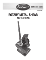
8" BENCH
SHEAR
INS TRUCTIONS
Item #20198

2 Eastwood Technical Assistance: 800.343.9353 >> techelp@eastwood.com
Your EASTWOOD 8” BENCH SHEAR for metal cutting is designed for quickly and cleanly cutting mild steel, aluminum and other metals. Torque-amplifying,
compound linkage provides low effort and a hardened steel ferrule in the Body, with mating Shear hole in the Blade, allow precision shearing of rod material.
CONTENTS
(1) 8” Bench Shear
(1) 17” Handle
SPECIFICATIONS
Maximum Sheet Steel Cutting Thickness: 11 Gauge/0.119” (3mm)
Maximum Flat Steel Bar Cutting Thickness: 0.19 x 1” (4.8mm x 25.4mm)
Maximum Round Steel Bar Cutting Diameter: 0.19 x 1” (4.8mm x 25.4mm)
TOOLS REQUIRED (not included)
• One 13mm Wrench
• One 14mm Wrench
• One 16mm Wrench
• Two 21mm Wrenches
DANGER indicates a hazardous situation which, if not avoided, will result in death or serious injury.
WARNING indicates a hazardous situation which, if not avoided, could result in death or serious injury.
CAUTION used with the safety alert symbol, indicates a hazardous situation which, if not avoided, could result in minor or moderate injury.
NOTICE is used to address practices not related to personal injury.
READ INSTRUCTIONS
• Thoroughly read and understand this manual before using.
• Save for future reference.
CUT AND CRUSH HAZARD!
• This Bench Shear has EXTREMELY SHARP cutting blades with amplified leverage on the upper blade which can quickly cause severe
injury or loss of fingers! Keep fingers and hands away from moving parts when operating.
SAFETY INFORMATION
The following explanations are displayed in this manual, on the labeling, and on all other information provided with this product:

To order parts and supplies: 800.343.9353 >> eastwood.com 3
CUT HAZARD!
• Handling sharp metal can cause serious cuts. Wear thick, well-fitting work gloves to prevent cuts from handling sharp metal.
EYE INJURY HAZARD!
• Metal particles can be ejected from the material when cutting. Sheet metal edges and corners are sharp and can injure eyes. Always
wear ANSI approved eye protection when operating this tool.
• Before beginning ANY work with this tool, it is absolutely necessary that it be securely bolted to a sturdy workbench anchored to the
floor or wall.
• Strenuous physical force may need to be applied to the Bench Shear during use. Failure to ensure proper footing can quickly result in a
fall which could inflict serious personal injury or property damage. Always work in a clean, uncluttered environment.
• Be sure there is sufficient working room around the tool to allow for safe handling of various sizes of metal.
• The Eastwood Bench Shear was specifically designed to be operated by one person only. Never have one person operate the Handle
while another handles the workpiece or serious injury could occur.
• Frequently inspect Blades. If cracks or chips develop, discontinue tool use immediately and replace damaged Blades.
SET UP
• The Eastwood Bench Shear must be securely mounted on a heavy, solid workbench, stand, floor etc., capable of holding the static weight of the unit plus
the stresses from operation.
• Place the Bench Shear over the chosen location then mark mounting hole locations by tracing holes in the base.
• The use of 1/2” through bolts & nuts or longer lag screws with
substantial washers and attachment to a structural member
is absolutely necessary.
ASSEMBLY
• Remove the supplied bolts from the Handle Stub, carefully align
the mounting holes of the Handle over the threaded holes in the
Stub, thread bolts through holes in Handle and into the Stub,
then tighten using a 16mm wrench (not included) (FIG 1).
Check for the presence of electrical, air or other utility lines under the mounting surface before drilling mounting holes.
FIG. 1

4 Eastwood Technical Assistance: 800.343.9353 >> techelp@eastwood.com
OPERATION
CUTTING SHEET METAL
• For maximum control and cutting force, begin all cuts by raising the handle fully and placing the edge of the metal at the point at which the blades
meet (FIG 2).
• Adjust the Material Foot to hold material in place by rotating the threaded post up or down, as required.
• For Straight Cuts; keep the metal stationary and flat as the Handle is pulled forward and downward.
• As the 1st cut has been done and the Upper Blade has reached the low point, raise the Handle then move the material forward placing the uncut area once
again at the Blade intersection point.
CUTTING FLAT MATERIAL
• With the Handle in the full up position, place flat stock as far back into blade intersection as feasible.
• Pull Handle firmly forward and down to cut material.
• Raise Handle and withdraw cut pieces.
CUTTING ROUND MATERIAL
• With the Handle in the full up position, insert round material to be cut into Shear Hole in Upper Blade and Main Body.
• Pull Handle firmly forward and down to shear material.
• Raise Handle and withdraw cut round stock.
FIG. 2
Handle
Handle Bolts
Handle Stub
Blade
Actuating Link
Upper Blade
Place Leading Edge of Metal Here
Lower Blade
Body
✓
✓
✓
✓
✓
✓
✓
✓
✓
Material
Foot
Shear Hole
✓
✓

To order parts and supplies: 800.343.9353 >> eastwood.com 5
BLADE REPLACEMENT
REMOVAL
Upper Blade
1. Raise Handle to open blades.
2. As a safety precaution, insert a large screwdriver or similar object
into the Shear Holes in the Blade and Shear Body to limit blade move-
ment (FIG 3). In addition, place a section of 2” x 4” or other suitable
wood between the upper and lower blades (FIG 3).
3. Using 13mm & 14mm wrenches, (not included) Loosen and remove
the Actuating Link Pivot Shoulder Bolt & Nut (FIG 4).
4. With two 21mm wrenches (not included), loosen and remove the
Main Pivot Locknut, Nut and Shoulder Bolt (FIG 5).
5. At this point the Upper Blade will be free. Very carefully hold the
Blade with one hand while the previously placed screwdriver is
removed from the Shear Holes.
6. Carefully withdraw the Upper Blade.
Lower Blade
1. With a 16mm Wrench (not included), loosen and remove the three
Lower Blade retaining Bolts and Washers (FIG 6).
2. Carefully withdraw the Lower Blade (FIG 7).
The blades are extremely sharp! Use extreme care
when handling to avoid severe cuts or loss of fingers!
The following steps must be followed in sequence to
reduce the danger of injury.
FIG. 4
FIG. 5
FIG. 3
FIG. 6
Screw Driver
Main
Pivot Bolt
✓
✓
Link
Pivot Bolt
2” x 4”
✓
Main Pivot Bolt,
Nut, and Locknut
✓
The following steps must be followed in sequence to
reduce the danger of injury.
FIG. 7
Lower
Blade
✓

6 Eastwood Technical Assistance: 800.343.9353 >> techelp@eastwood.com
FIG. 9
FIG. 10
FIG. 8
INSTALLATION
Lower Blade
1. Set the Lower Blade onto the ledge of Lower Main Body with the
three mounting holes aligned with those in the Main Body.
2. Place the three Mounting Bolts with Washers into the holes in the
front of the Main Body and thread them into the Blade (FIG 8).
3. Tighten Bolts with a 16mm wrench (not included).
UPPER BLADE
1. Set the Upper Blade into place behind the Lower Blade with the pivot
holes of the Upper Blade and Main Body aligned.
2. Place the Main Pivot Shoulder Bolt through the Upper Blade and Main
Body pivot holes.
3. Thread the Pivot Nut onto the Pivot Bolt until it is firmly finger-tight.
Do not overtighten which can cause binding (FIG 9).
4. Thread the Pivot Locknut onto the Pivot Bolt and using two 21mm
wrenches (not included), lock it into place against the Pivot Nut.
5. Carefully raise the Upper Blade and insert a large screwdriver into the
Shear Holes of the Upper Blade and Main Body (FIG 10).
6. In addition, for safety, place a section of 2” x 4” or other suitable
wood between the upper and lower blades (FIG 10).
7. Move the Handle slightly forward and back to achieve alignment of
the through holes of the Actuating Link and Upper Blade.
8. Insert the Pivot Shoulder Bolt and thread on the Nut then firmly finger
tighten. 13mm and 14mm Wrenches (not included) may be used
however do not overtighten which will cause binding (FIG 10).
9. Remove the screwdriver from the Shear Holes.
The following steps must be followed in sequence to
reduce the danger of injury.
The following steps must be followed in sequence to
reduce the danger of injury.

To order parts and supplies: 800.343.9353 >> eastwood.com 7
STORAGE
• Apply a thin film of light oil or rust-preventive to all bare steel areas.
• Store in a clean, dust-free, dry, dampness free area preferably covered with plastic sheeting.
MAINTENANCE
NOTE: Maintenance should be performed before each use.
• Check tightness of all hardware.
• Check operation for binding. Lubricate all pivot points periodically with a medium bodied lubricating oil.
• Inspect Blades for cracks, damage or premature wear. Replace if damaged.
• Clean chips, dirt and debris from Blades.
The blades are extremely sharp! Use extreme care when handling to avoid severe cuts or loss of fingers!
Produces
a Rough,
Jagged Cut or
Fails to Cut
Worn Blades Replace Blades.
Material Too Thick Refer to Maximum Material Specs.
TROUBLESHOOTING

© Copyright 2017 Easthill Group, Inc. 5/17 Instruction Item #20198Q Rev. 1
If you have any questions about the use of this product, please contact
The Eastwood Technical Assistance Service Department: 800.343.9353 >> email: techelp@eastwood.com
PDF version of this manual is available online >> eastwood.com/20198manual
The Eastwood Company 263 Shoemaker Road, Pottstown, PA 19464, USA
US and Canada: 800.343.9353 Outside US: 610.718.8335
Fax: 610.323.6268 eastwood.com
ADDITIONAL ITEMS
#20456 Replacement Blades
/
