Fujitsu AOYG12LUC Installation guide

Type
Installation guide
hcstueDsiaçnarFloñapsEonailatIάkIvηλλEsêugutroP
hsilgnE
eçkrüT
йикссуР
INSTALLATION MANUAL
For authorized service personnel only.
INSTALLATIONSANLEITUNG
Nur für autorisiertes Personal.
MANUEL D'INSTALLATION
Pour le personnel agréé uniquement.
MANUAL DE INSTALACIÓN
Solo para personal autorizado.
MANUALE D'INSTALLAZIONE
Ad uso esclusivo del personale autorizzato.
ΕΓΧΕΙΡΙΔΙΟ ΕΓΚΑΤΑΣΤΑΣΗΣ
Για εξουσιοδοτημένο προσωπικό σέρβις.
MANUAL DE INSTALAÇÃO
Apenas para técnicos autorizados.
РУКОВОДСТВО ПО УСТАНОВКЕ
Для уполномоченного персонала.
KURULUM KILAVUZU
Yetkili servis personeli içindir.
INSTALLATION MANUAL
AIR CONDITIONER
OUTDOOR UNIT
PART NO. 9319205014
9319205014_IM_EN.indd 19319205014_IM_EN.indd 1 12/9/2010 9:20:37 AM12/9/2010 9:20:37 AM
En-1
1. SAFETY PRECAUTIONS
1.1. For authorized service personnel only
WARNING
This mark indicates procedures which, if improperly per-
formed, might lead to the death or serious injury of the user.
For the room air conditioner to operate satisfactory, install it as outlined in this installa-
tion manual.
Connect the indoor unit and outdoor unit with the air conditioner piping and cords avail-
able standards parts. This installation manual describes the correct connections using
the standard accessories and the parts speci ed in this installation manual.
Have installation work done by authorized service personnel only.
Do not use an extension cord.
Do not turn on the power until all installation work is complete.
CAUTION
This mark indicates procedures which, if improperly
performed, might possibly result in personal harm to the user,
or damage to property.
When installing pipes shorter than 3 m, sound of the outdoor unit will be transferred to
the indoor unit, which will cause large operating sound or some abnormal sound.
This installation manual describes how to install the outdoor unit only.
To install the indoor unit, refer to the installation manual included with the indoor unit.
Be careful not to scratch the air conditioner when handling it.
After installation, explain correct operation to the customer, using the operating manual.
Let the customer keep this installation manual because it is used when the air condi-
tioner is serviced or moved.
The maximum length of the piping is 20 m. The maximum height difference of the pip-
ing is 15 m, if the units are further apart than these, correct operation can not be guar-
anteed.
2. ABOUT THE UNIT
2.1. Precautions for using R410A refrigerant
The basic installation work procedures are the same as conventional refrigerant (R22)
models.
However, pay careful attention to the following points:
Since the working pressure is 1.6 times higher than that of conventional refrigerant
(R22) models, some of the piping and installation and service tools are special. (See
the table below.)
Especially, when replacing a conventional refrigerant (R22) model with a new refrigerant
R410A model, always replace the conventional piping and flare nuts with the R410A piping
and are nuts.
Models that use refrigerant R410A have a different charging port thread diameter to pre-
vent erroneous charging with conventional refrigerant (R22) and for safety. Therefore,
check beforehand. [The charging port thread diameter for R410A is 1/2 inch.]
Contents
1. SAFETY PRECAUTIONS .......................................................................................... 1
2. ABOUT THE UNIT ..................................................................................................... 1
3. SELECTING THE MOUTING POSITION .................................................................. 2
4. INSTALLATION DIAGRAM ........................................................................................ 2
5. INSTALLATION ......................................................................................................... 2
6. PUMP DOWN ............................................................................................................ 4
Be more careful that foreign matter (oil, water, etc.) does not enter the piping than with
refrigerant (R22) models. Also, when storing the piping ,securely seal the opening by
pinching, taping, etc.
When charging the refrigerant, take into account the slight change in the composition of
the gas and liquid phases. And always charge from the liquid phase where refrigerant
composition is stable.
2.2. Special tools for R410A
Tool name Contents of change
Gauge manifold
Pressure is high and cannot be measured with a conven-
tional (R22) gauge. To prevent erroneous mixing of other
refrigerants, the diameter of each port has been changed.
It is recommended the gauge with seals -0.1 to 5.3 MPa
(-1 to 53 bar) for high pressure.
-0.1 to 3.8 MPa (-1 to 38 bar) for low pressure.
Charge hose
To increase pressure resistance, the hose material and base
size were changed.
Vacuum pump
A conventional vacuum pump can be used by installing a
vacuum pump adapter.
Gas leakage detector Special gas leakage detector for HFC refrigerant R410A.
Copper pipes
It is necessary to use seamless copper pipes and it is desirable that the amount of residual
oil is less than 40 mg/10 m. Do not use copper pipes having a collapsed, deformed or
discolored portion (especially on the interior surface). Otherwise, the expansion value or
capillary tube may become blocked with contaminants.
As an air conditioner using R410A incurs pressure higher than when using R22, it is neces-
sary to choose adequate materials.
Thicknesses of copper pipes used with R410A are as shown in Table1. Never use copper
pipes thinner than 0.8mm even when it is available on the market.
Thicknesses of Annealed Copper Pipes
Thickness (mm)
Nominal diameter
Outer diameter (mm)
R410A [ref.] R22
1/4 in.
6.35 0.80 0.80
3/8 in.
9.52 0.80 0.80
1/2 in.
12.7 0.80 0.80
WARNING
Do not use the existing (for R22) piping and are nuts.
If the existing materials are used, the pressure inside the refrigerant cycle will rise and
cause failure, injury, etc. (Use the special R410A materials.)
When installing and relocating the air conditioner, do not mix gases other than
the speci ed refrigerant (R410A) to enter the refrigerant cycle.
If air or other gas enters the refrigerant cycle, the pressure inside the cycle will rise to
an abnormally high value and cause failure, injury, etc.
2.3. Power
• The rated voltage
230V AC 50Hz.
WARNING
The rated voltage of this product is 230 V AC 50 Hz.
Before turning on the power, check if the voltage is within the 220 V -10 % to 240 V
+10 % range.
Always use a special branch circuit and install a special receptacle to supply power to
the room air conditioner.
Use a circuit breaker and receptacle matched to the capacity of the air conditioner.
Do not extend the power cable.
Perform wiring work in accordance with standards so that the air conditioner can be
operated safely and positively.
Install a leakage circuit breaker in accordance with the related laws and regulations
and electric company standards.
CAUTION
The power source capacity must be the sum of the air conditioner current and the cur-
rent of other electrical appliances. When the current contracted capacity is insuf cient,
change the contracted capacity.
When the voltage is low and the air conditioner is dif cult to start, contact the power
company the voltage raised.
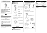
AIR CONDITIONER
OUTDOOR UNIT
INSTALLATION MANUAL
9319205014
9319205014_IM_EN.indd 19319205014_IM_EN.indd 1 12/9/2010 9:21:13 AM12/9/2010 9:21:13 AM
En-2
2.4. Electric requirement
Electric wire size and fuse capacity:
MODEL 12,000 ~ 14,000 BTU class
Power supply cord (mm
2
)
1.5
Connection cord (mm
2
) 1.5
Fuse capacity (A) 15
• Use conformed cable with Type245 IEC57.
• Install all electrical works in accordance to the national standard.
Install the disconnect device with a contact gap of at least 3 mm in all poles nearby the
units. (Both indoor unit and outdoor unit)
• Install the circuit breaker nearby the units.
2.5. Accessories
Drain pipe
1
2.6. Additional charge
Refrigerant suitable for a piping length of 15 m is charged in the outdoor unit at the factory.
When the piping is longer than 15 m, additional charging is necessary.
For the additional amount, see the table below.
Pipe length 15 m 20 m Rate
Additional refrigerant None +100 g 20 g/m
CAUTION
When adding refrigerant, add the refrigerant from the charging port at the completion
of work.
The maximum length of the piping is 20 m. If the units are further apart than this, correct
operation can not be guaranteed.
Between 15 m and 20 m, when using a connection pipe other than that in the table, charge
additional refrigerant with 20 g/1 m as the criteria.
3. SELECTING THE MOUNTING POSITION
Decide the mounting position with the customer as follows:
Do not set to a place where there is oily smoke, oil is used in the factory, the unit can
contact sea breeze, sul de gases will be generated in the hot spring area, corrosive
gases will be generated, animal may urine on the unit and ammonia will be generated
and a dusty place.
3.1. Outdoor unit
(1) If possible, do not install the unit where it will be exposed to direct sunlight.
(If necessary, Install a blind that does not interfere with the air ow.)
(2) Do not install the unit where a strong wind blows or where it is very dusty.
(3)
Do not install the unit where people pass.
(4)
Take you neighbors into consideration so that they are not disturbed by air blowing into their
windows or by noise.
(5)
Provide the space shown in gure so that the air ow is not blocked. Also for ef cient
operation, leave open three of the four directions front, rear, and both sides.
(6)
Install the unit where keep away more than 3m from the antenna of TV set and Radio.
(7) Outdoor unit should be set to a place where both drainage and itself will not be
affected when heating.
WARNING
Install at a place that can withstand the weight of the outdoor units and install positively
so that the units will not topple or fall.
CAUTION
Do not install where there is the danger of combustible gas leakage.
Do not install near heat sources.
In places where the outdoor temperature drops to 0 ˚C or lower, the drain water may
freeze and may stop up the drain or cause other outdoor unit trouble. Therefore take
measures so that the drain water will not freeze and clog the drain.
In the area with heavy snowfall, if the intake and outlet of outdoor unit is blocked with
snow, it might become dif cult to get warm and it is likely to cause of the breakdown.
Please construct a canopy and a pedestal or place the unit on a high stand (local
con gured).
If children under 10 years old may approach the unit, take preventive measures so that
they cannot reach the unit.
4. INSTALLATION DIAGRAM
Connection Cord
Conform to Type245 IEC57
[OUTDOOR UNIT]
10 cm or over
60 cm or over
10 cm or over
20 cm or over
25 cm or
over
5 cm or over
INDOOR UNIT
Outdoor unit
bottom
Drain pipe
Drain hose
Do not directly install it on the
ground, otherwise it will cause
failure.
To obtain better operation ef-
ficiency, when the outdoor unit
is installed, be sure to open the
front and left side.
54 cm
32 cm
CAUTION
When the outdoor temperature is 0 ˚C or less, do not use the accessory drain pipe
and drain cap. If the drain pipe and drain cap are used, the drain water in the pipe may
freeze in extreme cold weather. (Reverse cycle model only)
In the area with heavy snowfall, if the intake and outlet of outdoor units blocked with
snow, it might become dif cult to get warm and it is likely to cause of the breakdown.
Please construct a canopy and a pedestal or place the unit on a high stand (local
con gured).
5. INSTALLATION
5.1.
Outdoor unit installation
Set the unit on a strong stand such as thing made of concrete blocks to minimize shock
and vibration.
Do not set the unit directly on the ground because it will cause trouble.
Switch cover A, B removal
(1) Remove the three tapping screws.
(2) Push downward the Switch cover B.
(3) Push upward the Switch cover A.
Installing the Switch cover A, B
(1) After inserting the three hooks of Switch cover A,
then push upward, and then tighten the two tap-
ping screws.
(2) After inserting the three hooks of Switch cover B,
then push upward, and then tighten the one tap-
ping screw.
WARNING
Install the unit where it will not be tilted by more than 5°.
When installing the outdoor unit where it may exposed to strong wind, fasten it securely.
Hook
Hooks
Hooks
Switch cover A
Switch cover B
9319205014_IM_EN.indd 29319205014_IM_EN.indd 2 12/9/2010 9:21:14 AM12/9/2010 9:21:14 AM
En-3
5.2.
Outdoor unit wiring
(1) Remove the outdoor unit Switch cover A, B.
(2) Remove the outdoor unit Cord clamp and Nylon clamp.
(3) Bend the end of the cord as shown in the gure.
(4) Connect the end of the connection cord fully into the terminal block.
(5) Fasten the sheath with a cord clamp.
(6) Fasten the sheath with a nylon clamp.
(7) Install the Switch cover A, B.
Cord clamp
Nylon clamp
NL321
12 34
Outdoor unit terminal blockIndoor unit terminal block
Connection cord
Earth screw
Earth screw
Power supply Cord
NL321
25mm
12mm
5mm
5mm
12mm
20mm
Cord clamp
Earth
screw
20mm
12mm
5mm
5mm
12mm
20mm
Connection Cord Power supply Cord
Connection cord wiring
Run the connection cord to the rear of the outdoor unit within the
A
range of the arrows
shown in the figure.
(The Switch cover B becomes difficult to install.)
A
Connector cord
Nylon clamp
Screw
HOLE
HOLE
CAUTION
Match the terminal block numbers and connection cord colors with those of the indoor
unit.
Erroneous wiring may cause burning of the electric parts.
Connect the connection cords rmly to the terminal block. Imperfect installation may
cause a re.
Always fasten the outside covering of the connection cord with the cord clamp. (If the
insulator is chafed, electric leakage may occur.)
Securely earth the power cord.
Do not use the earth screw for an external connector. Only use for interconnection
between two units.
5.3. Connecting the piping
CONNECTION
(1) Install the outdoor unit wall cap (supplied with the optional installation set or pro-
cured at the site) to the wall pipe.
(2) Connect the outdoor unit and indoor unit pip-
ing.
(3) After matching the center of the are surface
and tightening the nut hand tight, tighten the
nut to the speci ed tightening torque with a
torque wrench. (Table 1)
FLARING
(1) Cut the connection pipe to the necessary
length with a pipe cutter.
(2) Hold the pipe downward so that cuttings will
not enter the pipe and remove the burrs.
(3) Insert the flare nut onto the pipe and flare
the pipe with a aring tool.
Insert the flare nut (always use the flare nut
attached to the indoor and outdoor units
respectively) onto the pipe and perform the are
processing with a are tool.
Use the special R410A are tool, or the conventional (for R22) are tool.
When using the conventional are tool, always use an allowance adjustment gauge and
secure the A dimension shown in table 2.
BENDING PIPES
(1) When bending the pipe, be careful not to crush it.
(2) To prevent breaking of the pipe, avoid sharp bends.
Bend the pipe with a radius of curvature of 70mm or over.
(3) If the copper pipe is bend the pipe or pulled to often, it will become stiff. Do not
bend the pipes more than three times at one place.
Tighten with two wrenches.
Torque
wrench
Wrench ( xed)
Flare nut
Indoor unit pipe
Connection
pipe
To prevent gas leakage, coat the are
surface with refrigerator oil.
Table 1 Flare nut size and tightening torque
Flare nut Diameter (mm)
Torque (N•m)
6.35 mm dia. 17
16 ~ 18
9.52 mm dia. 22
32 ~ 42
12.7 mm dia. 26
49 ~ 61
Table 2 Pipe outside diameter
Pipe outside
diameter
A (mm)
Flare tool for
R410A, clutch type
Conventional (R22) are tool
Clutch type Wing nut type
ø 6.35 mm (1/4") 0 to 0.5 1.0 to 1.5 1.5 to 2.0
ø 9.52 mm (3/8") 0 to 0.5 1.0 to 1.5 1.5 to 2.0
ø 12.7 mm (1/2") 0 to 5 1.0 to 1.5 1.5 to 2.0
CAUTION
Fasten a are nut with a torque wrench as instructed in this manual. If fastened too
tight, the are nut may be broken after a long period of time and cause a leakage of
refrigerant.
During installation, make sure that the refrigerant pipe is attached rmly before you run
the compressor. Do not operate the compressor under the condition of refrigerant piping
not attached properly with 2-way or 3-way valve open. This may cause abnormal pres-
sure in the refrigeration cycle that leads to breakage and even injury.
5.4. Air purge
Always use a vacuum pump to purge the air.
Refrigerant for purging the air is not charged in the outdoor unit at the factory.
Close the high pressure side valve of the gauge manifold fully and do not operate it during
the following work.
CAUTION
Refrigerant must not be discharged into atmosphere.
After connecting the piping , check the joints for gas leakage with gas leak detector.
(1) Check if the piping connections are secure.
(2) Check that the stems of 2-way valve and 3-way valve are closed fully.
(3) Connect the gauge manifold charge hose to the charging port of the 3-way valve (side
with the projection for pushing in the valve core).
(4) Open the low pressure side valve of the gauge manifold fully.
(5) Operate the vacuum pump and start pump down.
(6) Slowly loosen the are nut of the 3-way valve and check if air enters, then retighten
the are nut.
(When the are nut is loosened the operating sound of the vacuum pump changes
and the reading of the compound pressure gauge goes from minus to zero.)
(7) Pump down the system for at least 15 minutes, then check if the compound pressure
gauge reads -0.1 MPa (-76 cmHg, -1 bar).
(8) At the end of pump down, close the low pressure side gauge of the gauge manifold
fully and stop the vacuum pump.
(9) Slowly loosen the valve stem of the 3-way valve. When the compound pressure
Check if [L] is ared uniformly and
is not cracked or scratched.
Die
A
Pipe
9319205014_IM_EN.indd 39319205014_IM_EN.indd 3 12/9/2010 9:21:15 AM12/9/2010 9:21:15 AM
En-4
gauge reading reaches 0.1-0.2 MPa, retighten the valve stem and disconnect the
charge hose from the 3-way valve charging port.
(If the stem of the 3-way valve is opened fully before the charge hose is disconnect-
ed, it may be dif cult to disconnect the charge hose.)
(10) Fully open the valve stems of the 2-way valve and 3-way valve using a hexagon
wrench. (After the valve stem begins to turn, turn it with a torque of less than
2.9 N • m (30 kgf • cm) until it stops turning.)
(11) Firmly tighten the 2-way valve and 3-way valve blank cap and the charging port cap.
3-way valve
2
-
way
valve
Charging
port
cap
Vacuum pump
Charge
hose
Charge hose
Charging
port
Blank cap
Valve stem
Flare nut
Compound pressure gauge
Gauge manifold
Pressure gauge
High
pressure
side valve
(closed)
Low
pressure
side
valve
-0.1 MPa
(-76 cmHg
-1 bar)
Tightening torque
Blank cap 20.0 to 25.0 N • m (200 to 250 kgf • cm)
Charging port cap 12.5 to 16.0 N • m (125 to 160 kgf • cm)
5.5. Test run
• Perform test operation and check items below.
• For the test operation method, refer to the operating manual.
The outdoor unit, may not operate, depending on the room temperature. In this case,
keep on pressing the MANUAL AUTO button of the indoor unit for more than 10 seconds.
The operation indicator lamp and timer indicator lamp will begin to ash simultaneously
during cooling test run. Then, heating test run will begin in about three minutes when
HEAT is selected by the remote control operation. (Please follow the operating manual
for remote control operation.)
To end test operation, keep on pressing the MANUAL AUTO button of the indoor unit for
more than 3 seconds.
(When the air conditioner is run by pressing the test run button, the OPERATION indica-
tor lamp and TIMER indicator lamp of the indoor unit will simultaneously ash slowly.)
OUTDOOR UNIT
(1) Is there any abnormal noise and vibration during operation?
(2) Will noise, wind, or drain water from the unit disturb the neighbors?
(3) Is there any gas leakage?
6. PUMP DOWN
6.1. Pump down
PUMP DOWN OPERATION (FORCED COOLING OPERATION)
To avoid discharging refrigerant into the atmosphere at the time of relocation or disposal,
recover refrigerant by doing the cooling operation or forced cooling operation according
to the following procedure. (When the cooling operation cannot start in winter, and so on,
start the forced cooling operation.).
(1) Do the air purging of the charge hose by connecting the charging hose of gauge mani-
fold to the charging port of 3 way valve and opening the low-pressure valve slightly.
(2) Close the valve stem of 2 way valve completely.
(3) Start the cooling operation or following forced cooling operation. Keep on pressing the
MANUAL AUTO button of the indoor unit for more than 10 seconds. The operation in-
dicator lamp and timer indicator lamp will begin to flash simultaneously during test run.
(The forced cooling operation cannot start if the MANUAL AUTO button is not kept on
pressing for more than 10 seconds.)
(4) Close the valve stem of 3 way valve when the reading on the compound pressure
gage becomes 0.05~0 Mpa(0.5~0 kg/cm2).
(5) Stop the operation.
• Press the START/STOP button of the remote control unit to stop the operation.
Press the MANUAL AUTO button when stopping the operation from indoor unit side. (It
is not necessary to press on keeping for more than 10 seconds.)
CAUTION
During the pump-down operation, make sure that the compressor is turned off before
you remove the refrigerant piping.
Do not remove the connection pipe while the compressor is in operation with 2 way or 3
way valve open. This may cause abnormal pressure in the refrigeration cycle that leads
to breakage and even injury.
9319205014_IM_EN.indd 49319205014_IM_EN.indd 4 12/9/2010 9:21:19 AM12/9/2010 9:21:19 AM
  • Page 1 1
  • Page 2 2
  • Page 3 3
  • Page 4 4
  • Page 5 5

Fujitsu AOYG12LUC Installation guide

Type
Installation guide

Ask a question and I''ll find the answer in the document

Finding information in a document is now easier with AI