
1. SAFETY PRECAUTIONS
• Be sure to read this manual thoroughly before installation.
• Warnings and precautions indicated in this manual contain important information pertaining
to your safety. Be sure to observe them.
• Hand this manual, together with the operating manual, to the customer. Request the
customer to keep them on hand for future use, such as for relocating or repairing the unit.
WARNING
This mark indicates procedures which, if improperly performed,
might lead to the death or serious injury of the user.
• Installation of this product must be done by experienced service technicians or professional
installers only in accordance with this manual. Installation by non-professional or improper
installation of the product might cause serious accidents such as injury, water leakage,
electric shock, or re. If the product is installed in disregard of the instructions in this
manual, it will void the manufacturer’s warranty.
• Do not turn on the power until all work has been completed. Turning on the power before
the work is completed can cause serious accidents such as an electric shock or a re.
• If refrigerant leaks when you are working, ventilate the area. If the leaking refrigerant is
exposed to a direct ame, it may produce a toxic gas.
• Installation must be performed in accordance with regulations, codes, and standards for
electrical wiring and equipment in each country, region, or the installing place.
• Do not use this equipment with air or any other unspecied refrigerant in the refrigerant lines.
Excess pressure can cause a rupture.
• During installation, make sure that the refrigerant pipe is attached rmly before you run
the compressor. Do not operate the compressor under the condition of refrigerant piping
not attached properly with 2 way or 3 way valve open. This may cause abnormal pressure
in the refrigeration cycle that leads to rupture and even injury.
• During the pump-down operation, make sure that the compressor is turned off before you
remove the refrigerant piping.
Do not remove the connection pipe while the compressor is in operation with 2 way or 3
way valve open. This may cause abnormal pressure in the refrigeration cycle that leads to
rupture and even injury.
CAUTION
This mark indicates a potentially hazardous situation that may
result in minor or moderate injury or damage to property.
• Read carefully all of safety information written in this manual before you install or use the
air conditioner.
• This unit must be installed by qualied personnel with a capacity certication of handling
refrigerant uids. Refer to regulation and laws in use on installation place.
• Install the unit by following local codes and regulations in force in the place of installation,
and the instructions provided by manufacturer.
• This unit is part of a set constituting an air conditioner. The unit must not be installed alone
or be installed with non-authorized device by the manufacturer.
• Always use a separate power supply line protected by a circuit breaker operating on all
wires with a distance between contact of 3 mm for this unit.
• To protect the persons, ground the unit correctly, and use the power cable combined with
an Earth Leakage Circuit Breaker (ELCB).
• The units are not explosion proof, and therefore should not be installed in explosive
atmosphere.
• To avoid getting an electric shock, never touch the electrical components soon after the
power supply has been turned off. After turning off the power, always wait 10 minutes or
more before you touch the electrical components.
• This unit contains no user-serviceable part. Always consult experienced service technician
for repairing.
• Do not touch the aluminum ns of heat exchanger built-in the indoor or outdoor unit to
avoid personal injury when you install the unit.
• When moving or relocating the air conditioner, consult experienced service technicians for
disconnection and reinstallation of the unit.
• Do not place any other electrical products or household belongings under indoor unit or
outdoor unit. Dripping condensation from the unit might get them wet, and may cause
damage or malfunction of your property.
2. ABOUT THE UNIT
Precautions for using R410A refrigerant
• The basic installation work procedures are the same as conventional refrigerant (R22)
models.
However, pay careful attention to the following points.
• Since the working pressure is 1.6 times higher than that of conventional refrigerant (R22)
models, some of the piping and installation and service tools are special. (See the table
below.)
Especially, when replacing a conventional refrigerant (R22) model with a new refrigerant
R410A model, always replace the conventional piping and are nuts with the R410A piping
and are nuts.
• Models that use refrigerant R410A have a different charging port thread diameter to
prevent erroneous charging with conventional refrigerant (R22) and for safety. Therefore,
check beforehand. [The charging port thread diameter for R410A is 1/2 inch.]
• Be more careful that foreign matter (oil, water, etc.) does not enter the piping than with
refrigerant (R22) models. Also, when storing the piping, securely seal the opening by
pinching, taping, etc.
• When charging the refrigerant, take into account the slight change in the composition of
the gas and liquid phases. And always charge from the liquid phase where refrigerant
composition is stable.
Special tools for R410A
Gauge manifold
Pressure is high and cannot be measured with a conventional (R22) gauge.
To prevent erroneous mixing of other refrigerants, the diameter of each port has been
changed.
It is recommended the gauge with seals -0.1 to 5.3 MPa (-1 to 53 bar) for high pressure.
-0.1 to 3.8 MPa (-1 to 38 bar) for low pressure.
Charge hose
To increase pressure resistance, the hose material and base size were changed.
Vacuum pump
A conventional vacuum pump can be used by installing a vacuum pump adapter.
Gas leakage detector
Special gas leakage detector for HFC refrigerant R410A.
Copper pipes
It is necessary to use seamless copper pipes and it is desirable that the amount of residual oil
is less than 40 mg/10 m. Do not use copper pipes having a collapsed, deformed or discolored
portion (especially on the interior surface). Otherwise, the expansion value or capillary tube
may become blocked with contaminants.
As an air conditioner using R410A incurs pressure higher than when using R22, it is necessary
to choose adequate materials.
Thicknesses of copper pipes used with R410A are as shown in chart below. Never use copper
pipes thinner than 0.8mm even when it is available on the market.
Thicknesses of Annealed Copper Pipes
Thickness (mm)
Nominal diameter Outer diameter (mm) R410A [ref.] R22
1/4 in. 6.35 0.80 0.80
3/8 in. 9.52 0.80 0.80
WARNING
Do not use the existing (for R22) piping and are nuts.
If the existing materials are used, the pressure inside the refrigerant cycle will rise and
cause failure, injury, etc. (Use the special R410A materials.)
When installing and relocating the air conditioner, do not mix gases other than the
specied refrigerant (R410A) to enter the refrigerant cycle.
If air or other gas enters the refrigerant cycle, the pressure inside the cycle will rise to an
abnormally high value and cause failure, injury, etc.
For authorized service personnel only
WARNING
• For appropriate working of the air conditioner, install it as written in this manual.
• To connect indoor unit and outdoor unit, use air conditioner piping and cables available
through your local distributor. This manual describes proper connections using such
installation set.
• Installation work must be performed in accordance with national wiring standards by
authorized personnel only.
• Do not turn on the power until all work has been completed.
• Be careful not to scratch the air conditioner when handling it.
• After installation, explain correct operation to the customer, using the operating manual.
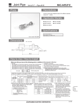
Accessories
The following installation accessories are supplied. Use them as required.
The following items are necessary to install this air conditioner. (The items are not included
with the air conditioner and must be purchased separately.)
Name Q’ty Name Q’ty
Connection pipe assembly 1 Wall cap 1
Connection cable 1 Saddle 1 set
Wall pipe 1 Drain hose 1
Decorative tape 1 Tapping screws 1 set
Vinyl tape 1 Sealant 1
3. ELECTRICAL REQUIREMENT
• Always make the air conditioner power supply a special branch circuit and provide a special
switch and receptacle. Do not extend the power cable.
• Install the disconnect device with a contact gap of at least 3 mm nearby the units.
Cable Size (mm
2
)
*1
Type Remarks
Connection cable 1.5 Type 60245 IEC 57 3 cable + Earth (Ground), 1 Ø 220V
*1 Selected sample: Select the correct cable type and size according to the country or
region’s regulations.
Max. wire length: Set a length so that the voltage drop is less than 2%. Increase the wire
diameter when the wire length is long.
WARNING
• The rated voltage of this product is 220 V AC 50 Hz.
• Before turning on the power, check if the voltage is within the 220 V -10 % to 240 V +10 %
range.
• Always use a special branch circuit and install a special receptacle to supply power to the
room air conditioner.
• Use a circuit breaker and receptacle matched to the capacity of the air conditioner.
• Do not extend the power cable.
• Perform wiring work in accordance with standards so that the air conditioner can be
operated safely and correctly.
• Install a leakage circuit breaker in accordance with the related laws and regulations and
electric company standards.
CAUTION
• The power source capacity must be the sum of the air conditioner current and the current
of other electrical appliances. When the current contracted capacity is insufcient, change
the contracted capacity.
• When the voltage is low and the air conditioner is difcult to start, contact the power
company for increasing the voltage.
AIR CONDITIONER
Wall Mounted Type
INSTALLATION MANUAL
PART No. 9332622225
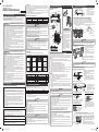
4. INSTALLATION DIAGRAM
Installation dimensions
Wall hook bracket
63 mm or more
70 mm or more
[INDOOR UNIT]
[OUTDOOR UNIT]
1,500 mm
or more
1,800 mm
or more
100 mm or more
(Wall cap)
Remote
controller
100 mm or more
600 mm or more
250 mm
or more
100 mm or more
200 mm or more
50 mm or more
454 mm
330 mm
Outdoor
unit bottom
Drain hose
CAUTION
• When the outdoor temperature
is 0 °C or less, do not use the
accessory drain pipe and drain
cap.
If the drain pipe and drain cap
are used, the drain water in the
pipe may freeze in extremely
cold weather. (Reverse cycle
model only)
• In the area with heavy snowfall,
if the intake and outlet of outdoor
unit is blocked with snow, it
might become difcult to get
warm and it is likely to cause
of the breakdown. Construct a
canopy and a pedestal or place
the unit on a high stand (local
congured).
5. SELECTING THE MOUNTING POSITION
Decide the mounting position with the customer as follows:
• Do not set to a place where there is oily smoke, oil is used in the factory, the unit can contact
sea breeze, sulde gases will be generated in the hot spring area, corrosive gases will be
generated, animal may urine on the unit and ammonia will be generated and a dusty place.
Indoor unit
(1) Install the indoor unit level on a strong wall which is not subject to vibration.
(2) The inlet and outlet ports should not be obstructed : the air should be able to blow all over
the room.
(3) Install the unit a dedicated electrical branch circuit.
(4) Do not install the unit where it will be exposed to direct sunlight.
(5) Install the unit where connection to the outdoor unit is easy.
(6) Install the unit where the drain pipe can be easily installed.
(7) Take servicing, etc. into consideration and leave the spaces shown in “ 4. INSTALLATION
DIAGRAM “. Also install the unit where the lter can be removed.
(8) Indoor unit should be set to a place where it is free from the inuence of the electronic
instant on/off type uorescent lamp and the thin TV screen.
Correct initial installation location is important because it is difcult to move unit after it is
installed.
Outdoor unit
(1) If possible, do not install the unit where it will be exposed to direct sunlight.
(If necessary, install a blind that does not interfere with the airow.)
(2) Do not install the unit where a strong wind blows or where it is very dusty.
(3) Do not install the unit where people pass.
(4) Take you neighbors into consideration so that they are not disturbed by air blowing into
their windows or by noise.
(5) Provide the space shown in “4. INSTALLATION DIAGRAM” so that the airow is not
blocked.
Also for efcient operation, leave open three of the four directions front, rear, and both sides.
(6) Install the unit where keep away more than 3m from the antenna of TV set and radio.
(7) Outdoor unit should be set to a place where both drainage and itself will not be affected
when heating.
WARNING
• Install the unit where is capable to support the weight of the unit. Secure the unit rmly so
that the unit does not topple or fall.
CAUTION
Do not install the unit in the following areas:
• Area with high salt content, such as at the seaside. It will deteriorate metal parts, causing
the parts to fail or the unit to leak water.
• Area lled with mineral oil or containing a large amount of splashed oil or steam, such as
a kitchen. It will deteriorate plastic parts, causing the parts to fail or the unit to leak water.
• Area where is close to heat sources.
• Area that generates substances that adversely affect the equipment, such as sulfuric gas,
chlorine gas, acid, or alkali.
It will cause the copper pipes and brazed joints to corrode, which can cause refrigerant
leakage.
• Area that can cause combustible gas to leak, contains suspended carbon bers or
ammable dust, or volatile inammables such as paint thinner or gasoline.
• If gas leaks and settles around the unit, it can cause a re.
• Area where animals may urinate on the unit or ammonia may be generated.
• Do not use the unit for special purposes, such as storing food, raising animals, growing
plants, or preserving precision devices or art objects. It can degrade the quality of the
preserved or stored objects.
• Install the unit where drainage does not cause any trouble.
• Install the indoor unit, outdoor unit, and power supply cable at least 1 m away from a
television or radio receivers. The purpose of this is to prevent TV reception interference or
radio noise.
(Even if they are installed more than 1 m apart, you could still receive noise under some
signal conditions.)
• If children may approach the unit, take preventive measures so that they cannot reach the
unit.
• Install the indoor unit on the wall where the height from the oor is more than 1.8 m.
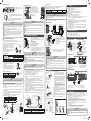
6. INDOOR UNIT INSTALLATION
Indoor unit piping direction
The piping can be connected in
the 6 directions indicated in the
following.
When the piping is connected in
direction 2 , 3 , 4 or 5 , cut along
the piping groove in the side of
the front cover with a hacksaw.
2: Right
outlet
3: Bottom outlet
1: Rear outlet
4: Left bottom outlet
6: Left rear
outlet
5: Left
outlet
(Rear)
Cutting the hole in the wall for the connecting piping
(1) Cut a 65 mm diameter hole in the wall at the position shown in the following.
(2) Cut the hole so that the outside end is lower (5 to 10 mm) than the inside end.
(3) Always align the center of the wall hole. If misaligned, water leakage will occur.
(4) Cut the wall pipe to match the wall thickness, stick it into the wall cap, fasten the cap with
vinyl tape, and stick the pipe through the hole.
(5) For left piping and right piping, cut the hole a little lower so that drain water will ow freely.
Wall hook bracket
Center mark Center mark
65 mm dia. hole 65 mm dia. hole
Fasten with vinyl tape
5 to
10 mm low
Wall pipe*
Wall cap*
(Inside) (Outside)
Wall
*Locally purchased
WARNING
Always use the wall pipe. If the wall pipe is not used, the cable that is connected between
the indoor unit and the outdoor unit may touch metal, and cause an electric discharge.
Installing the wall hook bracket
Wall hook bracket
Tapping screw
(1) Install the wall hook bracket so that it
is correctly positioned horizontally and
vertically.
If the wall hook bracket is tilted, water will
drip to the oor.
(2) Install the wall hook bracket so that it is
strong enough to support the weight of the
unit.
• Fasten the wall hook bracket to the wall with 5 or more
screws through the holes near the outer edge of the
bracket.
• Check that there is no rattle at the wall hook bracket.
CAUTION
Install the wall hook bracket both horizontally and vertically aligned. Misaligned installation
may cause water leakage.
Forming the drain hose and pipe
[Rear piping, Right piping, Bottom piping]
Pipe (top)
Indoor unit
drain hose
(bottom)
• Install the indoor unit piping in the direction of
the wall hole and bind the drain hose and pipe
together with vinyl tape.
• Install the piping so that the drain hose is at
the bottom.
• Wrap the pipe of the indoor unit that visible
from the outside with decorative tape.
• For right or bottom outlet piping, cut off the
piping outlet cutting groove with a hacksaw.
[For Left rear piping, Left piping]
Interchange the drain cap and the drain hose.
Indoor unit drain hose Drain cap
• For left or left bottom outlet piping,
cut off the piping outlet cutting
groove with a hacksaw.
• Remove the drain cap by pulling at
the projection at the end of the cap
with pliers, etc.
Installation method of Drain cap Installation method of drain hose
Screw hole
Drain cock
Drain hose
Screw
Drain xture
Vertically insert the drain hose toward
the inside, so that the drain xture can
accurately align with the screw hole around
the drain cock. After inserting and before
replacing, reinstall and x the removed
screws.
No gap
Hexagonal
wrench
Drain cock
Drain cap
Use a hexagonal wrench 4 mm at opposite
side to insert the drain cap, till the drain cap
contacts the tip of drain cock.
Removal method of drain hose
Screw Drain hose
Drain xture
Remove the screw
at the left of drain
hose and pull out
drain hose.
Hold around the joint of the drain hose during working.
As the screw is inside, be sure to use screwdriver treated with magnet.
Connection
pipe
(6.35 mm
dia.)
Bend (R70)
with a pipe
bender
Connection
pipe (9.52 mm dia.)
Align the marks.
• For left piping and left rear piping, align the marks on
the wall hook bracket and shape the connection pipe.
• Bend the connection piping at a bend radius of 70
mm or more and install no more than 35 mm from
the wall.
• After passing the indoor piping and drain hose
through the wall hole, hang the indoor unit on the
hooks at the top and bottom of the wall hook bracket.
Name and Shape Name and Shape Name and Shape Name and Shape
Q’ty Q’ty Q’ty Q’ty
Operating
manual
Installation
manual
(This manual)
Wall hook bracket
Remote
controller
Remote
controller
holder
Tapping screw
(large)
Tapping screw
(small)
Battery Cloth tape Air cleaning
lter
Air cleaning
lter frame
Drain pipe
1
1
1
1 1 1
212
5 2 2
Remote controller holder
Tapping screw (small)
PATH_No_9332622225_EN.indd 1 8/23/2560 BE 11:06 AM


 1
1
 2
2


Fujitsu ASYG07LLCD Installation guide
Fujitsu ASYG35LLCP Installation guide
Fujitsu RSG07LLCC Installation guide
Fujitsu ASGG12JLCA-P Installation guide
Fujitsu HOG12LTC Installation guide
Friedrich M18CFKIT Installation guide
Hitachi RAC-VX13CET Installation guide
Acson M5WMY15LR Installation guide
LG ARUV100LR2.AWGBASA Installation guide
Panasonic CS-E24RKUAW Installation guide
Trane ADAMO MCW 5247BA00 Installation guide
 Mitsubishi Electronics USA MAC-A455JP-E Installation guide
