Page is loading ...

Sit to Stand Dual Monitor Wall Mount Workstation -
Silver
Scan the QR code with your mobile device or follow the link
for helpful videos and specifications related to this product.
Instruction Manual
https://vivo-us.com/products/stand-sit2w
SKU: STAND-SIT2W
Chat live with an agent!
GET IN TOUCH | Monday-Friday from 7:00am-7:00pm CST

2
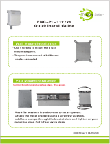
PACKAGE CONTENTS
WARNING!
If you do not understand these directions, or if you have any doubts about the safety of the
installation, please call a qualified technician. Check carefully to make sure there are no missing or
defective parts. Improper installation may cause damage or serious injury. Do not use this product
for any purpose that is not explicitly specified in this manual. Do not exceed weight capacity.
We cannot be liable for damage or injury caused by improper mounting, incorrect assembly or
inappropriate use.
NOTE: SOME HARDWARE INCLUDED MAY NOT BE USED
WARNING: CHOKING HAZARD
SMALL PARTS - NOT FOR CHILDREN UNDER 3 YEARS. ADULT SUPERVISION IS REQUIRED.
CAUTION!
DO NOT INSTALL INTO DRYWALL ALONE. VERIFY YOUR WALL CONSTRUCTION. USE WOOD STUDS TO
MOUNT. We include mounting for brick and concrete walls. If unsure, please contact us at vivo-us.
com, email at [email protected]om, or call us at 309-278-5303.
A (x1)
Arm
B (x1)
Pole
C (x1)
Tray
D (x1)
Monitor Arm
E (x2)
Decorative Cover
F (x2)
M8x24
G (x1)
4mm Allen
Wrench
H (x1)
6mm Allen
Wrench
M-A (x8)
M4x12
M-C (x8)
M4x16
M-B (x8)
M5x12
M-D (x8)
M5x16
M-F (x8)
Spacer
M-E (x8)
D5 Washer
W-A (x4)
Screw
W-B (x4)
Anchor
W-C (x3)
Washer

3
ASSEMBLY STEPS
2.2-13.2lbs
(1-6kg)
DO NOT EXCEED WEIGHT CAPACITY.
Failure to do so may result in serious injury.
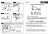
STEP 1
Hold arm (A) to wall where stud
is located and mark top hole
location with a pencil. Drill 2.2”
(55mm) deep hole using a 3/16”
(4.5mm) drill bit, and insert screw
(W-A) leaving 6mm of thread
exposed. Hang arm on screw, and
making sure arm is level, mark 2
additional drilling locations using
the vertically aligned holes. Drill
holes, then mount arm using
screws (W-A) with washers (W-C).
OPTION B: Concrete/Brick Installation
Hold arm (A) to wall where desired and mark top hole location with a pencil. Drill 2.4” (60mm) deep
hole using a 3/8” (10mm) drill bit, and insert anchor (W-B). Insert screw (W-A) leaving 6mm of thread
exposed. Hang arm on screw, and making sure arm is level, mark 3 additional drilling locations. Drill
holes, insert anchors (W-B), then mount arm using screws (W-A) with washers (W-C).
TOOLS NEEDED
Phillips
Screwdriver
Drill
Pencil
PER SCREEN
OPTION A: Wood Stud Installation

4
STEP 2
Remove two lower screws from back of pole (B) and set aside.
Attach tray (C) to pole using M8x24 bolts (F), and tighten with
6mm Allen wrench (H).
STEP 4
Remove front bracket from arm mount at top of
pole (B) using 4mm Allen wrench (G) as shown.
Set parts aside.
STEP 5
Slide decorative covers (E) on arm (A).
STEP 3
Remove knobs and slide VESA plates o from
brackets. Set parts aside for later use.
E
G

5
STEP 6
Attach monitor arm (D) using previously removed
bracket and screws, making sure adjustment screws
on monitor brackets are facing up. Tighten with
4mm Allen wrench (G).
STEP 7
Loosen top two screws on back
of pole (B) until 5mm of thread is
exposed on each. Slide pole onto
mount of arm (A). Attach with
previously removed screws, and
tighten all screws with 4mm Allen
wrench (G).
STEP 9
Slide VESA plates with monitors onto mounting
brackets of arm (D) and secure with previously
removed knobs.
OPTION A: Flat Back Monitor
For flat back monitors, attach VESA
plates using 12mm screws (M-A or
M-B) with washers (M-E).
STEP 8
OPTION B: Curved Back Monitor
For curved or recessed back monitors, use 16mm
screws (M-C or M-D) with washers (M-E) and
spacers (M-F).
M- A
M- B
M- E
M- C
M- D
M- E
M- F

6
STEP 11
STEP 12
STEP 10
Adjust gas spring strength using 6mm Allen wrench
(H). Turning clockwise will decrease strength, and
counter-clockwise will increase strength.
NOTE: Tighten socket set screw if the joint makes a
popping noise.
Adjust height of monitors using knob on back of pole (B). Correct individual monitor height by turning
the knob on each monitor bracket as shown. Use 6mm Allen wrench (H) if knobs are too sti to turn by
hand. Adjust rotation of tray (C) using 4mm Allen wrench (G) as shown if tray is not level.
To adjust tray to 10° tilt angle, first flip the tray up fully, then turn the supports in front of the hinge
upward. Set the keyboard tray back down. Allen wrenches (G, H) can be stored underneath the
keyboard tray as shown.

7
STEP 14
STEP 15
STEP 13
Use screwdriver to remove covers as shown in diagram. Insert cables.
Replace covers and tighten with screwdriver.
Adjust arms and monitors as desired.
NOTE: To install CPU Holder, please
refer to CPU Holder Manual.
NOTE: To install CPU Holder, please
refer to CPU Holder Manual.
NOTE: To install CPU Holder, please
refer to CPU Holder Manual.

LAST UPDATED: 10/08/2020
REV1
Open Monday - Friday 7:00am - 7:00pm CST,
our dedicated support team can oer immediate assistance with rapid response times. If any
parts are received damaged or defective, please contact us. We are happy to replace parts to
ensure you have a fully functioning product.
FOR MORE VIVO PRODUCTS, CHECK OUT OUR WEBSITE AT: www.vivo-us.com
AVG. RESPONSE TIME (within oice hrs): 1HR 8M
- 23% within < 15m
- 38% within < 30m
- 61% within < 1hr
- 83% within < 2hr
- 92% within < 3hr
Love your new VIVO setup and want to share?
Tag us in your photo! @vivo_us
AVG. RESOLUTION TIME (within oice hrs): < 15 M
www.vivo-us.com
Chat live with an agent!
AVG. RESOLUTION TIME (within oice hrs): 5M 4S
309-278-5303
/